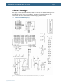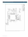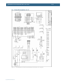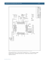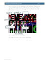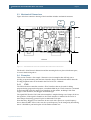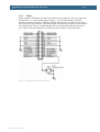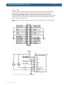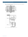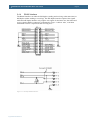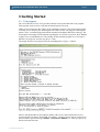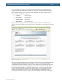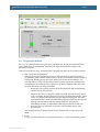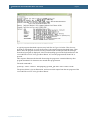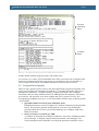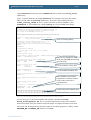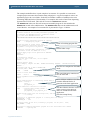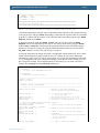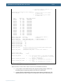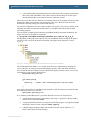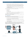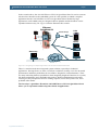
1
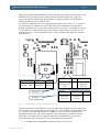
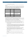
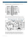
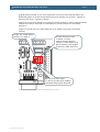
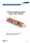
100M Ethernet QuickStart Board - User’s Guide
Copyright 2005 © Embedded Artists AB
100/10M Ethernet LPC2138
QuickStart Board User’s
Guide
Get Up-and-Running Quickly and
Start Developing on Day 1…
EA2-USG-0511 v1.1 Rev A
100/10M Ethernet LPC2138 QuickStart Board - User’s Guide
Page 2
Embedded Artists AB
Friisgatan 33
SE-214 21 Malmö
Sweden
[email protected]
http://www.EmbeddedArtists.com
Copyright 2005 © Embedded Artists AB. All rights reserved.
No part of this publication may be reproduced, transmitted, transcribed, stored in a retrieval
system, or translated into any language or computer language, in any form or by any means,
electronic, mechanical, magnetic, optical, chemical, manual or otherwise, without the prior
written permission of Embedded Artists AB.
Disclaimer
Embedded Artists AB makes no representation or warranties with respect to the contents
hereof and specifically disclaim any implied warranties or merchantability or fitness for any
particular purpose. Information in this publication is subject to change without notice and
does not represent a commitment on the part of Embedded Artists AB.
Feedback
We appreciate any feedback you may have for improvements on this document. Please send
your comments to [email protected].
Trademarks
InfraBed and ESIC are trademarks of Embedded Artists AB. All other brand and product
names mentioned herein are trademarks, services marks, registered trademarks, or registered
service marks of their respective owners and should be treated as such.
Copyright 2005 © Embedded Artists AB
100/10M Ethernet LPC2138 QuickStart Board - User’s Guide
Page 3
Table of Contents
1 Introduction
4
1.1
Contents
4
1.2
Features
4
1.3
Low Cost
5
1.3.1
1.4
Design and Production Services
5
Other QuickStart Boards and Kits
5
2 Board Design
6
2.1
Board Schematics (v1.1)
6
2.2
Board Schematics (v1.0)
8
2.3
Mechanical Dimensions
15
2.4
Examples
15
2.4.1
JTAG
15
2.4.2
Reset
16
2.4.3
SPI
17
2.4.4
RS485 Interface
19
3 Getting Started
3.1
Test program
20
3.2
Program Download
22
3.2.1
Philips LPC2000 Flash Utility
23
3.2.2
LPC21ISP
23
3.3
Program Development
25
3.3.1
QuickStart Build Environment
26
3.3.2
GCC
32
3.4
Installing QuickStart Build Environment
33
3.5
Sample Ethernet Driver
37
3.5.1
Build and Download Ethernet Driver
38
3.6
Developer’s QuickStart Kit – QuickStart Your Development
39
3.7
Typical Usage
40
4 CD-ROM and Product Registration
42
4.1
CD-ROM
42
4.2
Product Registration
42
5 Further Information
Copyright 2005 © Embedded Artists AB
20
43
100/10M Ethernet LPC2138 QuickStart Board - User’s Guide
Page 4
1 Introduction
Thank you for buying Embedded Artists’ 100/10M Ethernet LPC2138 QuickStart Board
based on Philips ARM7TDMI LPC2138 microcontroller and Davicoms DM9000E Ethernet
controller.
This document is a User’s Guide that describes the 100/10M Ethernet LPC2138 QuickStart
Board design along with the accompanying software and program development tools. The
document contains information on how to use and integrate the board in your own designs,
including electrical and mechanical information.
1.1 Contents
The box received when ordering the 100/10M Ethernet LPC2138 QuickStart Board contains
the following:
•
The 100/10M Ethernet LPC2138 QuickStart Board.
•
CD-ROM which includes additional material and programs, including complete and
evaluation versions of different development environments. Observe that bulk orders
(10 or 100 boards) only include one CD-ROM.
In addition, the following is needed in order to start developing applications with the
100/10M Ethernet LPC2138 QuickStart Board:
•
A DC power supply, 5.0 volt, capable of providing at least 200 mA (more if external
circuits need power from the 3.3 volt supply). The 100/10M Ethernet LPC2138
QuickStart Board does not contain reverse polarity protection.
Observe that the 100/10M Ethernet LPC2138 QuickStart Board does not contain any
reverse polarity protection. If voltage is applied with wrong polarity, the board will
likely be damaged.
•
A serial extension cable, DB9-male to DB9-female (DB9M-DM9F), for connecting
the 100/10M Ethernet LPC2138 QuickStart Board to a PC (for example, for
downloading program code into FLASH).
•
An optional JTAG interface, for program development debugging.
1.2 Features
Embedded Artists’ 100/10M Ethernet LPC2138 QuickStart Board lets you get up-andrunning quickly with Philips ARM7TDMI LPC2138 microcontroller. The small form factor
board offers many unique features that ease your development.
•
Philips ARM7TDMI LPC2138 microcontroller with 512 KByte program Flash and
32 KByte SRAM
•
Proven DM9000E 100/10 Mbps Ethernet MAC
•
Some LPC2138 I/O pins are available on expansion connectors
•
14.7456 MHz crystal for maximum execution speed
−
Phase-locked loop (PLL) multiplies frequency with four;
4 x 14.7456 MHz = 58.9825 MHz
•
32.768kHz RTC crystal
•
ESD/EMI protected RS232 channel with DSUB-9 connector
−
Copyright 2005 © Embedded Artists AB
Signals available on expansion connector
100/10M Ethernet LPC2138 QuickStart Board - User’s Guide
Page 5
•
RS422/RS485 interface
•
2 Kbit I2C E2PROM for storing non-volatile parameters like MAC address, IPaddress, subnet mask, and default gateway
•
On-board low-dropout voltage and reset generation
•
−
Generates +3.3V from a +5V supply
−
+3.3V available for external circuits, up to 300 mA
−
Power supply: 4.5-6 VDC, at least 200 mA
Simple and automatic program download (ISP) via RS232 channel
−
Circuit that automatically controls the bootloader from RS232 channel
•
Easy to connect to JTAG signals
•
Dimensions: 50 x 100 mm
−
Small form factor for easy integration
−
2x16 pins expansion I/O connector
−
Four layer PCB (FR-4 material) for best noise immunity
1.3 Low Cost
The 100/10M Ethernet LPC2138 QuickStart Board is very low cost and can be used for
prototyping / development as well as for OEM applications. Modifications for OEM
applications can be done easily, even for modest production volumes. Contact Embedded
Artists for further information about design and production services.
1.3.1
Design and Production Services
Embedded Artists provide design services for custom designs, either completely new or
modification to existing boards. Specific peripherals and I/O can be added easily to different
designs, for example, communication interfaces, specific analog or digital I/O, and power
supplies. Embedded Artists has a broad, and long, experience in designing industrial
electronics, in general, and with Philips LPC2xxx microcontroller family, in specific. Our
competence also includes wireless and wired communication for embedded systems. For
example IEEE802.11b/g (WLAN), Bluetooth™, ZigBee™, ISM RF, Ethernet, CAN, RS485,
and Fieldbuses.
1.4 Other QuickStart Boards and Kits
Visit Embedded Artists’ home page, www.EmbeddedArtists.com, for information about
other QuickStart boards / kits or contact your local distributor.
Copyright 2005 © Embedded Artists AB
100/10M Ethernet LPC2138 QuickStart Board - User’s Guide
Page 6
2 Board Design
This chapter contains detailed information about the electrical and mechanical design of the
100/10M Ethernet LPC2138 QuickStart Board. A number of example circuits are also
presented that will lower the threshold of start developing with the board.
2.1 Board Schematics (v1.1)
Figure 1 – 100/10M Ethernet LPC2138 QuickStart Board Schematic (v1.1) Page #1
Copyright 2005 © Embedded Artists AB
100/10M Ethernet LPC2138 QuickStart Board - User’s Guide
Figure 2 – 100/10M Ethernet LPC2138 QuickStart Board Schematic (v1.1) Page #2
Copyright 2005 © Embedded Artists AB
Page 7
100/10M Ethernet LPC2138 QuickStart Board - User’s Guide
2.2 Board Schematics (v1.0)
Figure 3 – 100/10M Ethernet LPC2138 QuickStart Board Schematic (v1.0) Page #1
Copyright 2005 © Embedded Artists AB
Page 8
100/10M Ethernet LPC2138 QuickStart Board - User’s Guide
Page 9
Figure 4 – 100/10M Ethernet LPC2138 QuickStart Board Schematic V1.0) Page #2
The board input power is +5.0V DC and is feed directly to a +3.3V low-dropout voltage
regulator. Power can be feed to the board via a 2.1mm circular connector or via the
expansion connector.
Copyright 2005 © Embedded Artists AB
100/10M Ethernet LPC2138 QuickStart Board - User’s Guide
Page 10
The board contains a 2kbit E2PROM (CAT1025) which also contains a reset generator. The
E2PROM can be used to store non-volatile parameters that are needed in a system, for
example IP-address, subnet mask, default gateway, and MAC address. The E2PROM is
connected to the LPC2138 via the I2C bus.
A red LED is connected to the reset signal and lights when reset is active, i.e., the signal is
low. The board also contains two more LEDs that can be controlled by the application
program. Digital I/O pin P1.24 controls LED1 (yellow for version 1.0 and green for version
1.1) and pin P1.25 controls LED2 (green for version 1.0 and yellow for version 1.1), see
schematic in Figure 3 for exact details. Figure 5 below illustrates the different LEDs and
their meaning.
Green
Yellow
Green
LED on = 100M
LED off = 10M
LED on =
full duplex
Ethernet
activity
Yellow
Red
Green
Controlled by
application via
P1.24
Reset
Controlled by
application
via P1.25
Version 1.0
Green
Yellow
Red
Controlled by
application
via P1.25
Reset
Version 1.1
Controlled by
application
via P1.24
Figure 5 – 100/10M Ethernet LPC2138 QuickStart Board LEDs
The microcontroller crystal frequency is 14.7456 MHz. This frequency has been selected in
order to allow close to maximum execution speed (4 x 14.7456 MHz = 58.9824 MHz, which
is very close to the maximum frequency, 60 MHz) as well as to provide standard serial
communication bit rates. The crystal frequency can be changed to any desired value for
OEM orders, provided that the conditions in the LPC2138 datasheet are met. Current
requirements are (but consult the most current datasheet for latest details):
•
Copyright 2005 © Embedded Artists AB
1-30 MHz if the on-chip phase-locked loop (PLL) is not used, or
100/10M Ethernet LPC2138 QuickStart Board - User’s Guide
•
Page 11
10-25 MHz if the PLL is to be used.
The board also contains a 32.768 kHz crystal that is used by the on-chip real-time clock on
LPC2138.
The LPC2138 microcontroller does not have an external data bus to connect to the Ethernet
controller. Instead, a data bus must be simulated via general purpose digital I/O pins on the
microcontroller. 14 pins are needed to connect the DM9000E Ethernet controller. Figure 4
shows the exact connection, which is also replicated in Table 1 below:
DM9000E Signal
LPC2138 I/O
Note
Data bus (D0 – D7)
P0.16 – P0.23
LPC2138 input / output pins
Command / Data (A2)
P1.16
LPC2138 output pin
Chip select
P1.21
LPC2138 output pin
Interrupt request
P0.15
LPC2138 input pin that can
be connected to the internal
interrupt controller.
Controller reset
P0.31
LPC2138 output pin
Memory cycle write
P1.23
LPC2138 output pin
Memory cycle read
P1.22
LPC2138 output pin
Table 1 – DM9000E Connections to LPC2138
The extra delay that is added when simulating the data bus will be a bottle neck for the data
throughput of the board. However, a continuous data throughput of 1Mbps can be achieved,
and few embedded systems have a greater need for data throughput.
The DM9000E has three LEDs connected. Their use and interpretation can be controlled via
registers in DM9000E. The three LEDs are mounted in the RJ45 connector.
Version 1.0 of the board contains a 2x16 pin expansion connector that contains some (not
all) of the LPC2138 I/O pins. Version 1.1 contains a 2x17 pin expansion connector.
•
Version 1.1 has the I2C bus available on the expansion connector. Version 1.0 does
not have this feature.
•
An ESD/EMI protected RS232 serial channel. Either UART channel #0 or channel
#1 can be connected to the RS232 interface signals. This is controlled by jumpers J3
and J5 (see Figure 8 for more information about jumper setting). The RS232 signals
are connected to the female 9-pol DSUB connector and the expansion connector.
•
A full duplex RS485 interface, connected to UART channel #1.
•
The LPC2138 SPI channel (MOSI, MISO, SCK signals) plus three extra general
purpose digital I/O signals for chip select of external SPI interfaces (P0.12, P0.13,
and P0.26). A MMC/SD card interface can for example easily be created.
•
Four analog inputs and one analog output. These signals can also be general purpose
digital I/O signals.
•
An active-low reset input as well as the reset output (from the reset controller,
CAT1025).
•
Power to the board (+4.5-6V DC) can be feed via the expansion connector.
•
The internal +3.3V voltage regulator is also connected so external circuits can be
feed.
Copyright 2005 © Embedded Artists AB
100/10M Ethernet LPC2138 QuickStart Board - User’s Guide
Page 12
The board expansion connector is a standard 2.54mm 2x16 (or 2x17) pin row. Figure 6
below illustrates the expansion connector and the signals it carries.
Figure 6 – 100/10M Ethernet LPC2138 QuickStart Board Expansion Connector
Version 1.1 of the board has an additional two pins, pin 33 and pin 34. Pin 33 is I2C-SCL
(P0.2) and pin 34 is I2C-SDA (P0.3). See Figure 7 below for an explanation of pin positions.
New pin 34, SDA
New pin 33, SCL
Expansion connector pin 1
Figure 7 – 100/10M Ethernet LPC2138 QuickStart Board Expansion Connector, PCB View v1.1
The board has direct and automatic support for program downloading (via ISP) over the
RS232 serial channel. The RS232 signal DTR controls the reset signal to the LPC2138
microcontroller. The RS232 signal RTS is connected to pin P0.14 in the LPC2138
microcontroller. This pin is sampled after reset and determines if the internal bootloader
Copyright 2005 © Embedded Artists AB
100/10M Ethernet LPC2138 QuickStart Board - User’s Guide
Page 13
program shall be started, or not. A low signal after reset enters the bootloader mode. The
RTS/DTR signals can be disconnected from the microcontroller via two links / jumpers on
the board. See Figure 8 below for details.
Jumper J10 connects the RS485 receive signal to UART channel #1. Observe that the RS232
interface must not be connected to UART channel #1 at the same time as the RS485
interface is.
Jumpers J3 and J5 select if UART channel #0 or #1 shall be connected to the RS232
interface.
Jumper J10; enable RS485
interface to UART #1
In order from left to right:
J3 (RxD), J5 (TxD)
Jumpers in lower position
connects UART channel #0 to
RS232 interface, and in upper
position to UART channel #1.
In order from left to right:
J7 (P0.14), J8 (Reset) for enabling
automatic ISP program download
Figure 8 – 100/10M Ethernet LPC2138 QuickStart Board Jumpers
Copyright 2005 © Embedded Artists AB
100/10M Ethernet LPC2138 QuickStart Board - User’s Guide
Page 14
There is an unfortunate error in the schematic for version 1.0 of the board. The RTS and CTS
signals of the RS232 interface have been switched. The signal from pin 7 of U2 (the RTS
signal) has been cut and disconnected from its (erroneous) connection to the RS232 DSUB
connector. The problem does not exist in boards after v1.0. The problem can also be fixed
for v1.0 boards, as seen in Figure 9 below.
U2, pin 7
U2, SP3232E
Already cut on
solder side
U2, pin 8
Cut here and connect
EMI filter to U2, pin 7
Connect EMI
filter to U2, pin 8
DSUB-9 Connector
Figure 9 – RTS and CTS Error in Schematic and PCB, v1.0
Note that this error does not appear on version 1.1 of the board.
Copyright 2005 © Embedded Artists AB
100/10M Ethernet LPC2138 QuickStart Board - User’s Guide
Page 15
2.3 Mechanical Dimensions
Figure 10 below contains a drawing of the board that includes mechanical measures.
J2
pin 1
J6
50 mm
100 mm
Figure 10 – 100/10M Ethernet LPC2138 QuickStart Board Mechanical Dimensions
The board is 100x50 mm in dimension and the mounting holes are places 90x40 mm apart,
as seen in the drawing above.
2.4 Examples
This section contains a few sample / illustrative circuit examples that will help you to
quickly get up-and-running with the board interface design. Detailed information about the
on-chip peripheral units can be found in the LPC2138 User’s Manual.
2.4.1
JTAG
The LPC2138 microcontroller contains a JTAG interface that can be used for debug
purposes during program development. A standard ARM 20 pin JTAG connector is mounted
on the board and works for many JTAG interfaces on the market, including J-link from
Segger, Ulink from Keil, and Wiggler from MacRaigor.
The signal RTCK on the LPC2138 microcontroller is sampled during reset. Jumper J6 drives
the signal low. If the signal is found low, the JTAG interface is enabled. Pin P1.26-P1.31
then changes from being general I/O pins to dedicated JTAG pins.
Note that many Wiggler JTAG interfaces do not work with a processor crystal frequency
above about 10 MHz. If this is the case, the crystal frequency can be changed by desoldering
the 14.7456 MHz crystal and replace it with another suitable one.
Copyright 2005 © Embedded Artists AB
100/10M Ethernet LPC2138 QuickStart Board - User’s Guide
2.4.2
Page 16
Reset
The on-board I2C E2PROM (CAT1025) also contains a reset generator. The reset signal will
be held active (i.e., low) until the supply voltages, +3.3V, is within margins. The reset
duration is typically 200 mS (consult the CAT1025 datasheet for exact details). The output
reset signal is an open-collector / open-drain output. An external reset source can also control
the reset generator. Figure 11 below illustrate how an external push-button can generate a
reset. Observe that an external driver should be an open-collector / open-drain driver.
Figure 11 – Example External Reset Push-button
Copyright 2005 © Embedded Artists AB
100/10M Ethernet LPC2138 QuickStart Board - User’s Guide
2.4.3
Page 17
SPI
The LPC2138 microcontroller has an on-chip SPI serial communication channel (actually
two, but only one of then is available on the expansion connector). Figure 12 below
illustrates how a SD/MMC memory card can be connected to the 100/10M Ethernet
LPC2138 QuickStart Board. In this example, pin P0.12 is used as chip select for the external
SPI unit. Pins P0.13 and P0.26 are used for checking if a memory card actually is inserted
and if it is write protected, or not.
Observe that one chip select signal is requires for each external chip that is connected to the
SPI bus.
Figure 12 – Example SPI Interface for SD/MMC Connector
Copyright 2005 © Embedded Artists AB
100/10M Ethernet LPC2138 QuickStart Board - User’s Guide
Page 18
Figure 13 below illustrates how serial E2PROM chip and a shift register (for I/O expansion)
also can be connected to the SPI bus.
2
Figure 13 – Example SPI Interface with E PROM and I/O Expansion
Copyright 2005 © Embedded Artists AB
100/10M Ethernet LPC2138 QuickStart Board - User’s Guide
2.4.4
Page 19
RS485 Interface
The RS485 interface can either be full duplex (sending and receiving at the same time) or
half duplex (either sending or receiving). The full duplex interface requires four signals
while the half duplex interface only requires two signals. In the latter case, the transit and
receive signals shall be connected, as illustrated in Figure 14 below. Also, a 120 ohm
termination resistor is required on the receiving end.
Figure 14 – Example RS485 Interface
Copyright 2005 © Embedded Artists AB
100/10M Ethernet LPC2138 QuickStart Board - User’s Guide
Page 20
3 Getting Started
3.1 Test program
The 100/10M Ethernet LPC2138 QuickStart Board comes preloaded with a test program.
This program can be used to verify that the board operates correctly.
LEDs can be connected to the signals on the expansion connector. The test program outputs
a running-zero to the port pins, meaning that one LED at a time will light (in a running-one
pattern). Also, a terminal program should be attached to the RS232 DSUB-9 connector. The
test program will output test information regarding the 32.678 kHz crystal test, the E2PROM
(registry) test, and the RS485 test. The settings for the terminal program are: 115.2 kbps, 8
data bits, no parity bits, and one stop bit (i.e., 8N1).
The output from the test program will look something like in Figure 15 below.
Figure 15 – Example Test Program Output
Observe that the RS485 test will indicate failure if the receive and transmit lines are not
connected with each other (TH and RH, TL and RL). Jumper J10 must also be inserted. It is
hence normal to get the message “RS485 interface ERROR!!!” when you power up
the board for the first time.
Copyright 2005 © Embedded Artists AB
100/10M Ethernet LPC2138 QuickStart Board - User’s Guide
Page 21
The test program also contains a TCP/IP stack and a small web server application. It is
possible to PING the board and also surfing to it using (for example) Internet Explorer™.
The IP-address settings can be set via the UART during the first three seconds after the
board is started. The default settings are:
•
IP-address:
192.168.1.230
•
Subnet mask:
255.255.255.0
•
Default gateway:
192.168.1.1
•
MAC address:
21.6.152.1.114.15
Figure 16 below shows the first web server page and the contents is an illustration (or
exposé, if you like) of what our Ethernet Developer’s QuickStart Kit can help you to quickly
create.
Figure 16 – Example Web Server Output
The Applet example illustrate how to control the system in real-time, both sending data and
receiving real-time data. With the help of Applets, it is easy to create advanced and
professional looking user interfaces. Figure 17 below shows how the applet looks like. The
two LEDs that are under application program control can be controlled via simple pushbuttons in the applet interface. A slider also illustrates how to send user input data to the
system. The slider position is printed on the console output. The temperature bar graph
illustrates to an Applet can receive real-time data and display the information. When
pressing the Start button, a process in the system starts sending real-time data to the applet.
Copyright 2005 © Embedded Artists AB
100/10M Ethernet LPC2138 QuickStart Board - User’s Guide
Page 22
Figure 17 – Applet User Interface Example
3.2 Program Download
For now, it is assumed that the program to be downloaded is already developed and there
exist a HEX-file to be downloaded. This HEX-file represents the binary image of the
application program.
There are basically two ways of downloading a program into the LPC213x microcontroller:
•
ISP – In-System Programming
The LPC2138 microcontroller provides on-chip bootloader software that allows
programming of the internal flash memory over the serial channel. The bootloader is
activated by pulling port pin P0.14 low during reset of the microcontroller. The
100/10M Ethernet LPC2138 QuickStart Board contains circuits for automatically
controlling pin P0.14 and the reset signal over the RS232 channel. This allows the
program download to be fully automated.
o
Philips provides a utility program for In-System Flash (ISP) programming
called LPC2000 Flash Utility.
o
Alternatively, there is a program called LPC21ISP that can be used. Source
code is available. This program also provides a terminal functionality, which
can be very helpful when developing your application program. The same
serial channel that is used to download the program is typically also used for
printing out information from the running program. The program
immediately switch to terminal mode after program download and will
hence not miss any characters sent on the serial channel directly after
program start.
The installation files for both programs can be found on the accompanying CDROM.
•
Copyright 2005 © Embedded Artists AB
JTAG
For specific information about program download (i.e., Flash programming) with a
100/10M Ethernet LPC2138 QuickStart Board - User’s Guide
Page 23
JTAG interface, consult the manual for the specific JTAG interface that is used (e.g.,
J-link from Segger, Ulink from Keil, or Wiggler from MacRaigor).
Connect all two jumpers / links (J7 – J8) on the 100/10M Ethernet LPC2138 QuickStart
Board. This will connect the RS232 channel to the active control over pin P0.14 and the
reset signal.
After program download, both jumpers / links can be left connected, or removed if needed. If
for example the PC end controls the RS232 signals DTR and/or RTS during normal program
execution, then it might be required that jumpers / links J7 and J8 are removed after program
download.
3.2.1
Philips LPC2000 Flash Utility
Philips LPC2000 Flash Utility program looks like Figure 18 below.
Figure 18 – Philips LPC2000 Flash Utility Screenshot
Configure the dialog as shown above. The program will control the RS232 signals DTR and
RTS if the appropriate checkbox is checked, and hence provide fully automated program
download.
Test connection with the 100/10M Ethernet LPC2138 QuickStart Board by pressing the
Read Device ID button. The text fields for Part ID and Boot Loader ID will then contain
uploaded information from the microcontroller. Observe that the XTAL Freq. must be set to
appropriate value. The default mounted crystal frequency on the 100/10M Ethernet LPC2138
QuickStart Board is 14.7456 MHz. In this case the value 14746 shall be written in the text
box. If the crystal frequency has been changed, make sure the appropriate value is set. If no
connection can be established test with a low Baud Rate, for example 1200 bps. Also verify
that the correct COM-port has been selected (under Connected to Port).
Select the HEX file to be downloaded and then press the Upload to Flash button.
The downloaded program will immediately start after the download (i.e. the Upload to Flash
operation is ready) is the option Execute Code after Upload is checked.
3.2.2
LPC21ISP
The LPC21ISP program is made publicly available by Martin Maurer. Source code is also
available at: http://engelschall.com/~martin/lpc21xx/isp/index.html. Figure 19 below shows
the command syntax for the program.
Copyright 2005 © Embedded Artists AB
100/10M Ethernet LPC2138 QuickStart Board - User’s Guide
Page 24
Figure 19 – LPC21ISP Portable Command Line ISP Screenshot
A typical program download sequence may look like in Figure 20 below. Here, the test
program is downloaded. As seen, the first part is the actual program download phase. Then
this is done, the program switches to being a terminal (the second part) and the messages
from the test program is displayed. It also sends anything typed on the keyboard back to the
100/10M Ethernet LPC2138 QuickStart Board. As seen the program ends when ESC is
pressed.
This sequence illustrates the benefits from using the program as a terminal directly after
program download. No characters are missed after program start.
The used command is:
lpc21isp –term –control testprogram_lpc213x_qsb.hex com1 115200 14746
The picture below is just an illustration, and not an actual output from the test program of the
100/10M Ethernet LPC2138 QuickStart Board.
Copyright 2005 © Embedded Artists AB
100/10M Ethernet LPC2138 QuickStart Board - User’s Guide
Page 25
Program
Download
Phase
Terminal
Phase
Figure 20 – LPC21ISP Portable Command Line ISP Download Screenshot
Another benefit with this program is that it runs under Linux.
Use version 1.28, or later, of LPC21ISP.EXE since older versions must be recompiled with
increased reset timeout (when the program tries to synchronize to the 100/10M Ethernet
LPC2138 QuickStart Board). The timeout should be increased to at least 350 ms.
3.3 Program Development
There are many options when it comes to the actual application program development. First
of all, you must select a development environment, i.e., an editor (preferably with project
management capabilities), a compiler package (compiler plus linker), and a debugger.
Fortunately, there are many different choices for ARM program development, each with its
pros and cons. The list below is far from complete but gives a general overview. The
accompanying CD-ROM (see Section 4.1 for more details) contains many of these programs
/ environments.
•
QuickStart Build Environment from Embedded Artists
Embedded Artists has created a complete GCC build environment for all QuickStart
boards. This will ease program development for novel users. By installing the
QuickStart Build Environment you will automatically get a complete setup of the
build environment.
•
Rowley Associates CrossWorks for ARM
A complete development environment from Rowley Associates, including an editor,
project manager, a complete compiler build environment, and a debugger. The
version included on the CD-ROM is a 30-day fully functional evaluation version.
Copyright 2005 © Embedded Artists AB
100/10M Ethernet LPC2138 QuickStart Board - User’s Guide
Page 26
•
IAR Embedded Workbench
A complete development environment from IAR Systems, including an editor,
project manager, a complete compiler build environment, and a debugger. The
version shipped on the CD-ROM has a 32 Kbyte program size limit, but is fully
functional in all other aspects.
•
Keil uVision
This is another complete development environment, but from Keil. It includes an
editor, project manager, a complete compiler build environment, and a debugger. An
evaluation version can be downloaded from Keils homepage. One version of the
development environment is based on the GCC compiler (currently version 3.3.1 of
GCC).
•
Programmers notepad
This is a very good editor and project manager that is increasing in popularity. The
program can easily be integrated with the GCC compiler.
•
Eclipse + CDT
This is a very good development environment (editor and project manager) with
specific support for C/C++ code development. It does not contain a compiler but can
easily be connected to one, for example GCC.
•
GCC distribution GNUARM
A complete distribution of GCC, specifically for ARM processors. Current version
of GCC is 3.4.3 and the new 4.0.0, and it is constantly updated.
•
WinARM
This is another distribution that not only contains GCC but also Programmers
Notepad, LPC21ISP, a terminal program, and JTAG drivers.
3.3.1
QuickStart Build Environment
The QuickStart Build Environment is a complete build environment for GCC including
program downloading via ISP. The build environment is built around a bash script. This
script sets up all necessary paths. When installing the QuickStart Build Environment you will
automatically get shortcuts to this bash script. A practical feature is that there can be
different scripts for different hardware platforms, for controlling different hardware specific
details of the platforms. There can also be many different compilers (including different
versions of the same compiler) without conflicting with each other.
The use of the bash script is optional but is recommended for non-experienced users.
A typical project has two subdirectories; build_files and startup. Figure 21 below
illustrate the general structure.
Figure 21 – Typical Project Directory Structure
The subdirectory build_files contains a general makefile and linker script files. The
subdirectory startup contains a configurable startup framework for QuickStart Board
projects. The startup files form a library that is linked to the main application.
The makefiles have a hierarchical structure. Each project, either an executable program file
or a library, has a simple makefile that just describe the specifics of the project. This
Copyright 2005 © Embedded Artists AB
100/10M Ethernet LPC2138 QuickStart Board - User’s Guide
Page 27
simple makefile includes the general makefile that is placed in the build_files
subdirectory.
Figure 22 below illustrates the simple makefile. The example comes from the startup
library, found under the startup subdirectory. The name of the resulting library is
libea_startup_thumb.a. Two C-source code files are listed: consol.c and
framework.c. An assembler file called startup.S is also included in the library.
##########################################################
#
# General makefile for building executable programs and
# libraries for Embedded Artists' QuickStart Boards.
# (C) 2001-2005 Embedded Artists AB
#
##########################################################
# Name of target (executable program or library)
NAME
= libea_startup_thumb
Name of resulting library.
# ELF-file contains debug information, or not
# (possible values for DEBUG are 0 or 1)
# Extra debug flags can be specified in DBFLAGS
DEBUG
= 1
#DBFLAGS =
# Optimization setting
# (-Os for small code size, -O2 for speed)
OFLAGS = -Os
# Extra general flags
# For example, compile for ARM / THUMB interworking (EFLAGS = -mthumb-interwork)
EFLAGS = -mthumb-interwork
# Program code run in ARM or THUMB mode
# Can be [ARM | THUMB]
CODE
= ARM
The files are compiled in ARM
mode with THUMB interworking
(see EFLAGS).
# List C source files here.
CSRCS
= consol.c \
framework.c
List all included C source files.
# List assembler source files here
ASRCS
= startup.S
List all included assembler files.
# List subdirectories to recursively invoke make in
SUBDIRS =
# List additional libraries to link with
LIBS
=
# Add include search paths
INC
= -I .
Select whether an executable
program file or a library shall be
created. One of the lines is
commented out.
# Select if an executable program or a library shall be created
#PROGRAM_MK = true
LIBRARY_MK = true
Include the general makefile here.
#######################################################################
include ../build_files/general.mk
#######################################################################
Figure 22 – Example QuickStart Build Environment Makefile from Startup Library
As seen in Figure 22 above the makefile ends with the command: include
build_files/general.mk. This is a general make file that is part of the complete
build environment. This part contains all specific details of compiler and linker invocation.
Also at the end, the target must be decided; either an executable program or a library. Either
PROGRAM_MK or LIBRARY_MK must be set to true.
Copyright 2005 © Embedded Artists AB
100/10M Ethernet LPC2138 QuickStart Board - User’s Guide
Page 28
The example makefile above is quite simple to its structure. It is possible to create more
complex project structures that contains many subprojects. A typical example is to have an
application project in a root folder. Under this root folder a number of subdirectories exist
containing different blocks of functionality. For example, this can be a Real-Time Operating
System and a TCP/IP stack. This calls for a recursive makefile structure.
The makefile in the root filer will create an executable program. It also includes the
makefile in each of the subdirectories. The makefiles that exist in subdirectories will
create libraries. An example of a root make file is presented in Figure 23 below.
##########################################################
#
# General makefile for building executable programs and
# libraries for Embedded Artists' QuickStart Boards.
# (C) 2001-2005 Embedded Artists AB
#
##########################################################
# Name of target (executable program or library)
NAME
= testprogram_10m_eth
Name of resulting program file.
# Path and name of linker script file
# Only needed for executable program files
LD_SCRIPT = build_files/link_rom.ld
Define linker script.
# ELF-file contains debug information, or not
# (possible values for DEBUG are 0 or 1)
# Extra debug flags can be specified in DBFLAGS
DEBUG
= 1
#DBFLAGS =
# Optimization setting
# (-Os for small code size, -O2 for speed)
OFLAGS = -Os
# Extra general flags
# For example, compile for ARM / THUMB interworking (EFLAGS = -mthumb-interwork)
EFLAGS =
The files are compiled in THUMB
mode.
# Program code run in ARM or THUMB mode
# Can be [ARM | THUMB]
CODE
= THUMB
The root folder only contains one
file, the main-file.
# List C source files here.
CSRCS
= main.c
# List assembler source files here
ASRCS
=
# List subdirectories to recursively invoke make in
SUBDIRS = startup \
tcpip \
pre_emptive_os
# List additional libraries to link with
LIBS
= startup/libea_startup_thumb.a \
tcpip/tcpip.a \
pre_emptive_os/pre_emptive_os.a
# Add include search path for startup files, and
INC
= -I./startup
Three different subdirectories that
contains different blocks of
functions in the final application.
The three libraries that are created
in the recursive invocation of
make are included in the final
application.
other include directories
Note the startup library.
# Select if an executable program or a library shall be created
PROGRAM_MK = true
#LIBRARY_MK = true
# Output format on hex file (if making a program); can be [srec | ihex]
HEX_FORMAT = ihex
# Program to download executable program file into microcontroller's FLASH
DOWNLOAD
= lpc21isp.exe
Copyright 2005 © Embedded Artists AB
100/10M Ethernet LPC2138 QuickStart Board - User’s Guide
Page 29
# Configurations for download program
DL_COMPORT = com1
DL_BAUDRATE = 115200
DL_CRYSTAL = 14746
#######################################################################
include build_files/general.mk
#######################################################################
Figure 23 – Example QuickStart Build Environment Root Makefile and Recursive Invocation
To build the application program, start a command prompt (the bash script), change directory
to the project root, and type: make. Depending on the make file content, either an executable
program or a library will be created. To also download the executable program, type: make
deploy instead of just make.
A final note about the make file; make clean will erase all object files and make
depend will recreate dependency files (this is also always done when typing just make).
Finally, make terminal will just start the terminal function in the download program
(lpc21isp). The specific settings for using the ISP download program can be set with the
DL_XXX variables (as seen at the end of Figure 23 above).
As already mentioned, the startup files form a configurable startup framework. This is often
called a Board Support package or BSP for short. It contains the very basic startup and
initialization code as well as a console with printf()- and scanf()-like functionality. The BSP
is very configurable and can be changed according to your specific needs. Each project can
have its specific settings. The configuration file is listed in Figure 24 below, and can be
found in file config.h in the startup subdirectory.
/******************************************************************************
*
* Copyright:
*
(C) 2000 - 2005 Embedded Artists AB
*
* Description:
*
Framework for ARM7 processor
*
*****************************************************************************/
#ifndef _config_h_
#define _config_h_
/******************************************************************************
* Defines, macros, and typedefs
*****************************************************************************/
#define FOSC 14745600
/* External clock input frequency
(must be between 10 MHz and 25 MHz) */
#define USE_PLL 1
/* 0 = do not use on-chip PLL,
1 = use on-chip PLL) */
/* PLL multiplication factor (1 to 32) */
/* PLL division factor (1, 2, 4, or 8) */
/* Peripheral bus speed divider (1, 2, or 4) */
#define PLL_MUL 4
#define PLL_DIV 2
#define PBSD
4
/* initialize the MAM (Memory Accelerator Module) */
#if (FOSC * PLL_MUL) < 20000000
#define MAM_TIMING
1
/* number of CCLK to read from the FLASH */
#elif (FOSC * PLL_MUL) < 40000000
#define MAM_TIMING
2
/* number of CCLK to read from the FLASH */
#else
#define MAM_TIMING
3
/* number of CCLK to read from the FLASH */
#endif
#define MAM_SETTING 2
/* 0=disabled,
1=partly enabled (enabled for code prefetch,
but not for data),
2=fully enabled */
#define IRQ_HANDLER
Copyright 2005 © Embedded Artists AB
1
/* 0 = Jump to common IRQ handler
100/10M Ethernet LPC2138 QuickStart Board - User’s Guide
Page 30
1 = Load vector directly from VIC, i.e.,
LDR PC,[PC,#-0xFF0] */
/*initialize the exception vector mapping */
#define MAM_MAP
1
/* 1 = exception
at 0x0000
2 = exception
at 0x4000
/*
* CHIP
SRAM SIZE
SRAM START ADDRESS
* LPC2104
16 * 1024
0x40000000
* LPC2105
32 * 1024
0x40000000
* LPC2106
64 * 1024
0x40000000
* LPC2114
16 * 1024
0x40000000
* LPC2119
16 * 1024
0x40000000
* LPC2124
16 * 1024
0x40000000
* LPC2129
16 * 1024
0x40000000
* LPC2194
16 * 1024
0x40000000
* LPC2131
8 * 1024
0x40000000
* LPC2132
16 * 1024
0x40000000
* LPC2134
16 * 1024
0x40000000
* LPC2136
32 * 1024
0x40000000
* LPC2138
32 * 1024
0x40000000
* LPC2210
16 * 1024
0x40000000
* LPC2214
16 * 1024
0x40000000
* LPC2220
64 * 1024
0x40000000
* LPC2290
16 * 1024
0x40000000
* LPC2292
16 * 1024
0x40000000
* LPC2294
16 * 1024
0x40000000
*/
#define SRAM_SADDR
0x40000000
/*
#define SRAM_SIZE
(32 * 1024)
/*
#define SRAM_TOP
(SRAM_SADDR+SRAM_SIZE)
/*
#define SRAM_EADDR
(SRAM_SADDR+SRAM_SIZE-1) /*
#define
#define
#define
#define
#define
#define
stackSize_SYS
stackSize_SVC
stackSize_UND
stackSize_ABT
stackSize_IRQ
stackSize_FIQ
#define STK_SIZE
#define STK_SADDR
SRAM starting address */
LPC2138 */
SRAM end address + 1 */
SRAM end address */
600
64
64
64
600
64
(stackSize_SYS+stackSize_SVC+stackSize_UND+stackSize_ABT+
stackSize_IRQ+stackSize_FIQ)
(SRAM_EADDR+1-STK_SIZE) /* Stack start address */
#define CONSOL_UART
#define CONSOL_BITRATE
0
115200
#define USE_NEWLIB
0
#define CONSOLE_API_PRINTF
1
#define CONSOLE_API_SCANF
1
#endif
vectors are in FLASH
0000,
vectors are in SRAM
0000
*/
/* 0 = do not use newlib (= save about 22k FLASH),
1 = use newlib = full implementation of printf(),
scanf(), and malloc() */
/* 0 = printf() = sendString,
1 = simple, own implementation of printf() */
/* 0 = none,
1 = simple, own implementation of scanf() */
/* _config_h_ */
Figure 24 – Board Support Package (BSP) Configuration File
There are three versions of the consol in order to best fit different situations:
•
A very simple version that basically only supports printing strings (without any
formatting parts) and printing numbers (decimal or hexadecimal).
•
A simple printf() implementation that supports the simplest formatting tags. The
implementation has been designed for lest possible stack usage (about 40 bytes).
Copyright 2005 © Embedded Artists AB
100/10M Ethernet LPC2138 QuickStart Board - User’s Guide
•
Page 31
A full ANSI printf() implementation from newlib (part of the compiler environment
that comes with GNUARM). This routine requires about 600 bytes of stack space
and should normally not be used in resource constraint systems.
The code size for the first two alternatives is minimal (about 2k in program size for the entire
framework). When using printf() from newlib, the code size is about 30 k for the entire
framework (including a large part of the newlib library).
Just edit the configuration file above and recompile your project. The recursive nature of the
makefiles will make sure that the startup library is recompiled and linked with the final
executable program.
You can find an example project under the QuickStart Build Environment installation. See
Figure 25 below for the path. It is typically:
c:/program/InfraBed/evboards/LPC2xxx-gcc-newlib-vX_X_X_X.
The beginning of the path can be specific for your installation and the ending of the path is
specific for the version of the build environment. The figure below illustrates version
2_0_0_0.
Figure 25 – Sample Project Files under QuickStart Build Environment Installation
The startup framework (BSP) is very simple and can best be understood by studying the
source code files. If using the console functionality (printf()- and scanf()-like functions)
observe that the function eaInit() must be called before printf() and the console can be used.
The following code segment illustrates this.
#include <ea_init.h>
...
...
int main(void)
{
eaInit(); //Now, the console/printf can be used
...
}
Also observe that whenever the BSP printf() should be used, the following include file must
be included into the source code file.
#include <printf_P.h>
As a summary; Embedded Artists’ QuickStart Build Environment is comprised of:
•
A make build environment, controlled by bash script. A program or library build is
started via the command: make.
•
A program download feature, by using the LPC21ISP program. A program build and
download is started via the command: make deploy.
•
A Board Support Package (BSP) with startup code and console functions (i.e.,
printf() and scanf()-like functionality).
Copyright 2005 © Embedded Artists AB
100/10M Ethernet LPC2138 QuickStart Board - User’s Guide
3.3.2
Page 32
GCC
This will be very similar to the QuickStart Build Environment example, except that you will
have to set up all paths manually and create your own startup files. The make files will also
be a bit more complex. An example makefile is presented in Figure 26 below. More
complex examples than the makefile below also exist.
#
# Example makefile that creates a program called ‘test’, containing the
# C-source code files: main.c, eeprom.c, and i2c.c plus the assembler
# file startup.S
#
LIBS
DEBUG
CFLAGS
INCLUDE
ARMCC
OBJS
LDFLAGS
=
=
=
=
=
=
=
-g
-Wall -nostartfiles -mthumb-interwork –mthumb
-Iinc/ -Iinc/specific/
#specify include paths here
arm-elf-gcc
main.o eeprom.o i2c.o startup.o
-Wl,-Trom.ld
#this file controls the linker
all: test.hex
test: $(OBJS)
arm-elf-gcc $(CFLAGS) $(LDFLAGS) $(OBJS) $(LIBS) -o test.elf
%.o: %.c
arm-elf-gcc -c $(INCLUDE) $(CFLAGS) $<
%.o: %.S
arm-elf-gcc -c $(INCLUDE) $(CFLAGS) $<
%.o: %.c
arm-elf-gcc -c $(INCLUDE) $(CFLAGS) $<
%.hex: %
arm-elf-objcopy -O ihex $<.elf $@
clean:
rm -f *.o test.elf test.hex
Figure 26 – Example GCC Makefile
Copyright 2005 © Embedded Artists AB
100/10M Ethernet LPC2138 QuickStart Board - User’s Guide
Page 33
3.4 Installing QuickStart Build Environment
This section describes the necessary steps of program installation that is needed to get the
QuickStart Build Environment ready for your use.
•
Copyright 2005 © Embedded Artists AB
Start with installing the GNUARM distribution that is included in the CD-ROM. The
current version of the file is called: bu-2.15_gcc-3.4.3-c-c++-java_nl1.12.0_gi-6.1.exe. There is also a newer, but less well tested, version (based
on GCC v4.0.0). Only use this newer version if you are an experienced user.
The installation is very simple and straightforward. It’s just following the default
installation steps as illustrated in the pictures below:
100/10M Ethernet LPC2138 QuickStart Board - User’s Guide
Page 34
Use the default
installation
directory
If you want to
save space on
your harddisk,
you can
deseclect the
Big Endian
component.
Copyright 2005 © Embedded Artists AB
100/10M Ethernet LPC2138 QuickStart Board - User’s Guide
Page 35
Install the
Cygwin DLLs.
Copyright 2005 © Embedded Artists AB
100/10M Ethernet LPC2138 QuickStart Board - User’s Guide
•
Copyright 2005 © Embedded Artists AB
Page 36
Now install the LPC2xxx-gcc-newlib_vX_X_X_X QuickStart Build
Environment (vX_X_X_X is the current version of the file). The installation is also
in this case very simple and straightforward. Just follow the default installation
steps.
100/10M Ethernet LPC2138 QuickStart Board - User’s Guide
Page 37
Use the default
installation
directory
Observe that if the compiler is not installed on the default location
(c:/Program/GNUARM/) the new path must be set in the files build.sh and
build_environment.sh. Both files can be found in:
C:\Program\InfraBed\evboards\LPC2xxx-gcc-newlib-vX_X_X_X\bin).
It is the variable COMPILERDIR2 that must be set (can be found on line 13 in both files).
The compiler path must be to the GNUARM/bin directory.
Observe that the path above must contain the correct version number instead of
…vX_X_X_X\bin. It may for example be: …v2_1_0_0\bin.
3.5 Sample Ethernet Driver
The sample driver project is very simple. Both a polled and an interrupt driven
implementation is presented. The driver consists of two (or three) C source code files:
main.c, ethdrv_dm9000.c, and ethisr.c (if interrupt implementation).
•
Copyright 2005 © Embedded Artists AB
The file ethdrv_dm9000.c is the actual sample Ethernet driver that connects the
DM9000E Ethernet controller to the I/O pins of the LPC2138 processor. It also
100/10M Ethernet LPC2138 QuickStart Board - User’s Guide
Page 38
contains all send and receive functions that are needed for sending/receiving
Ethernet frames.
•
The file main.c contains a sample application that implements ARP and PING
functionality. This simple application illustrates how the Ethernet driver can be
interfaced. The main program uses polling to check if any Ethernet frame has been
receive, but it can easily be changed to an fully interrupt driven solution.
•
The file ethisr.c contains the interrupt handler that must be compiled in ARM
mode. Since all other files are compiled in THUMB mode, the interrupt driver must
be compiled as a separate library.
3.5.1
Build and Download Ethernet Driver
The following simple steps will guide you through the build and download process:
•
Copy and unzip the sample Ethernet driver zip-file into a suitable project directory.
•
Select if you want to work with the polled or the interrupt implementation by
changing to suitable working directory (irq or polled).
•
Open the file main.c in your favorite editor. Search for the variable localIP.
The default value is 192.168.1.230. Change this if you need. You can easily
check if you need to change the IP address, or not. Open a DOS prompt/command
shell. Type: ipconfig. Then you will get information about your computer’s IPaddress. You must make sure that the IP-address of the Ethernet board is on the
same subnet as your computer.
•
Open the LPC2xxx-gcc-newlib QuickStart Build Environment. You will find it
under the program start menu: Embedded Artists/LPC2xxx-gcc-newlib
•
Change the working directory to where you unzipped the sample Ethernet driver
project.
•
Type: make and view the result. It should look something like in the picture below.
You can study the sizes of the program code that you have just built.
Copyright 2005 © Embedded Artists AB
100/10M Ethernet LPC2138 QuickStart Board - User’s Guide
•
Page 39
Make sure that power is connected to the 100/10M Ethernet LPC2138 QuickStart
Board, a serial cable to the PC, and that all four jumpers on the board is inserted on
the correct place (for automatic ISP program download).
All four jumpers in
upper position (as
viewed in the picture)
•
Type: make deploy and verify that the program actually is downloaded into the
100/10M Ethernet LPC2138 QuickStart Board. Also verify that the phrase:
Detected DM9000E… is printed.
•
Now it’s time to test if it is possible to ping the board. Open a DOS
prompt/command shell. Type: ping 192.168.1.230 (or whatever IP address
you have selected). Verify that the board is actually responding to the ping requests.
Now, all you have to do is start integrating the Ethernet driver into your favorite TCP/IP
stack …or you can have a look at the next section and get a QuickStart.
3.6 Developer’s QuickStart Kit – QuickStart Your Development
The Developer’s QuickStart Kit contains a pre-designed software platform with all necessary
infrastructure functionality for using the 100/10M Ethernet LPC2138 QuickStart Board in
industrial applications. The kit allows you to quickly evaluate the applicability of Ethernet in
YOUR application. Extensive documentation is included in order to lower the threshold of
start using the kit even further. You can start to develop and include your own application on
day 1.
The Developer’s QuickStart Kit includes a pre-designed software platform that integrates a
mayor part of the needed infrastructure for advanced Ethernet applications. By using the
platform you avoid the long and narrow “do-it-yourself” way when start using new
technology with all these typical activities:
Copyright 2005 © Embedded Artists AB
100/10M Ethernet LPC2138 QuickStart Board - User’s Guide
Page 40
•
Researching (RTOS, Compiler/IDE, TCP/IP Stack, Web Server, File System)
•
Hardware design (this is of course not part of the software platform, but an activity
that is typically also required if you don’t buy an off-the-shelf hardware board).
•
Configuration (RTOS, Compiler/IDE, TCP/IP Stack, Web Server, File System,
Board Support Package)
•
Testing (hardware, each individual software component, integrating the platform)
The included components in the Developer’s QuickStart Kit are:
•
TCP/IP stack
•
Web Server
•
Pre-emptive RTOS
•
Static File System, for storing web server static data (HTML-pages, pictures, etc.)
•
Registry for storing application parameters like IP-address, etc.
The pre-installed test program is built around the Ethernet Developer’s QuickStart Kit and
demonstrates some web server possibilities.
3.7 Typical Usage
The 100/10M Ethernet LPC2138 QuickStart Board can be used to easily create advanced
MMI (Man-Machine-Interfaces) based on Internet technologies:
•
Use the web server to expose information and parameters that can be controlled.
•
Use the file system to store HTML files and picture files.
•
Use the serial channel to communicate (expose information or control parameters)
with ANY System.
•
Access the system directly via a local area network or indirectly via wireless bridges
(WLAN or Bluetooth).
Figure 27 below illustrates how the 100/10M Ethernet LPC2138 QuickStart Board can be
connected to any embedded system and expose internal variables in this system, or
alternatively controls internal parameters in the system. Communication with the (arbitrary)
embedded system can be done via the RS232 or RS485 serial channel.
Ethernet
QuickStart Kit
PDA
ANY System
Wireless Bridge
Expose
Application
Control
Laptop
Stationary
Ethernet
WWW
Figure 27 – Typical Ethernet QuickStart Application Scenario
Copyright 2005 © Embedded Artists AB
100/10M Ethernet LPC2138 QuickStart Board - User’s Guide
Page 41
In the scenario above, the 100/10M Ethernet LPC2138 QuickStart Board is used to create an
advanced user interface to the embedded system. It is also possible to embed a complete
application into the 100/10M Ethernet LPC2138 QuickStart Board. Relatively large
applications can be added to the pre-designed software platform and the hardware can be
expanded with necessary I/O. Figure 28 below illustrates this scenario.
Ethernet
QuickStart Kit
Wireless Bridge
PDA
ANY System
Application
Laptop
Stationary
Ethernet
WWW
Figure 28 – Integrating a Complete Application into the Ethernet QuickStart Board
There is a trend towards more integrated system solutions, especially in industrial
applications. Driving factors are more cost effective solutions (in many cases also increased
performance) and better possibilities for surveillance, diagnostics, and maintenance. There
are many interesting business possibilities when integrating diagnostic functions in a system,
like better maintenance and a profitable after market. Remote administration and remote
control gives the prerequisites of lower working expenses, lower total system costs, and a
profitable after market.
The Developer’s QuickStart Kit and the 100/10M Ethernet LPC2138 QuickStart Board
allows you to experiment and develop these kinds of applications!
Copyright 2005 © Embedded Artists AB
100/10M Ethernet LPC2138 QuickStart Board - User’s Guide
Page 42
4 CD-ROM and Product Registration
The accompanying CD-ROM contains a lot of information and programs that will
QuickStart your program development! Observe that there may be newer versions of
different documents and programs available than the ones on the CD-ROM. See Section 4.2
for information about the product registration process, which allows you to always have
access to the latest versions.
4.1 CD-ROM
The following is included on the CD-ROM:
•
The preloaded test program as a HEX-file.
•
The two different ISP download programs.
•
Datasheets of all circuits on the 100/10M Ethernet LPC2138 QuickStart Board.
•
QuickStart Build Environment from Embedded Artists, which contains a complete
setup of a build environment for GCC.
•
A complete development environment: Rowley Associates CrossWorks for ARM,
30-day evaluation version.
•
A complete development environment: IAR Embedded Workbench for ARM,
Kickstart Edition with 32 Kbyte program size limit.
•
Another complete development environment: GCC, GNUARM distribution,
including compiler, linker, make, and debugger.
•
The program Programmers Notepad, which is a very good program development
editor and project manager.
•
The Eclipse development environment including the CDT (C/C++ Development
Tools) project.
4.2 Product Registration
By registering as a customer of Embedded Artists you will get access to more valuable
material that will get you up-and-running instantly:
•
Access to a Real-Time Operating System (RTOS), in the form of a library that can
be used for non-commercial applications.
•
Access to a number of sample applications that demonstrated different (peripheral)
functions in the LPC2138 processor.
•
Access to the latest versions of all information and programs on the CD-ROM.
Registering is easy and done quickly.
1) Go to http://www.EmbeddedArtists.com, select Support and then Register.
2) Type in the products serial number (can be found on the 100/10M Ethernet LPC2138
QuickStart Board or on the package carrying the board) along with your personal
information.
Copyright 2005 © Embedded Artists AB
100/10M Ethernet LPC2138 QuickStart Board - User’s Guide
Page 43
5 Further Information
The LPC2138 microcontroller is a complex circuit and there exist a number of other
documents with a lot more information. The following documents are recommended as a
complement to this document.
[1] Philips LPC213x Datasheet
http://www.semiconductors.philips.com/acrobat/datasheets/
LPC2131_32_34_36_38_2.pdf
[2] Philips LPC213x User’s Manual
http://www.semiconductors.philips.com/acrobat/usermanuals/
UM10120_1.pdf
[3] Philips LPC2138 Errata Sheet
http://www.semiconductors.philips.com/acrobat/erratasheets/2138.pdf
[4] ARM7TDMI Technical Reference Manual. Document identity: DDI0029G
http://www.arm.com/pdfs/DDI0029G_7TDMI_R3_trm.pdf
[5] ARM Architecture Reference Manual. Document identity: DDI0100E
Book, Second Edition, edited by David Seal, Addison-Wesley: ISBN 0-201-73719-1
Also available in PDF form on the ARM Technical Publications CD
[6] ARM System Developer’s Guide – Designing and Optimizing System Software, by
A.N. Sloss, D Symes, C. Wright. Elsevier: ISBN 1-55860-874-5
[7] Embedded System Design on a Shoestring, by Lewin Edwards.
Newnes: ISBN 0750676094.
[8] GNU Manuals
http://www.gnu.org/manual/
[9] GNU ARM tool chain for Cygwin
http://www.gnuarm.com
[10] An Introduction to the GNU Compiler and Linker, by Bill Gatliff
http://www.billgatliff.com
[11] LPC2000 Yahoo Group. A discussion forum dedicated entirely to the Philips
LPC2xxx series of microcontrollers.
http://groups.yahoo.com/group/lpc2000/
[12] The Insider’s Guide to the Philips ARM7-Based Microcontrollers, by Trevor Martin.
http://www.hitex.co.uk/arm/lpc2000book/index.html
Especially observe document [3]. There exist a number of bugs in the processor that is
important to be aware of.
Observe that there can be newer versions of the documents than the ones linked to here.
Always check for the latest information / version.
Datasheets for all circuits on the 100/10M Ethernet LPC2138 QuickStart Board are included
on the accompanying CD-ROM.
Copyright 2005 © Embedded Artists AB