1
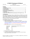
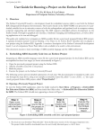
LPC2103 USB QuickStart Board - User’s Guide
Copyright 2006 © Embedded Artists AB
LPC2103 USB QuickStart
Board User’s Guide
Get Up-and-Running Quickly and
Start Developing on Day 1…
EA2-USG-0602 v1.0 Rev B
LPC2103 USB QuickStart Board - User’s Guide
Page 2
Embedded Artists AB
Friisgatan 33
SE-214 21 Malmö
Sweden
[email protected]
http://www.EmbeddedArtists.com
Copyright 2005-2006 © Embedded Artists AB. All rights reserved.
No part of this publication may be reproduced, transmitted, transcribed, stored in a retrieval
system, or translated into any language or computer language, in any form or by any means,
electronic, mechanical, magnetic, optical, chemical, manual or otherwise, without the prior
written permission of Embedded Artists AB.
Disclaimer
Embedded Artists AB makes no representation or warranties with respect to the contents
hereof and specifically disclaim any implied warranties or merchantability or fitness for any
particular purpose. Information in this publication is subject to change without notice and
does not represent a commitment on the part of Embedded Artists AB.
Feedback
We appreciate any feedback you may have for improvements on this document. Please send
your comments to [email protected].
Trademarks
InfraBed and ESIC are trademarks of Embedded Artists AB. All other brand and product
names mentioned herein are trademarks, services marks, registered trademarks, or registered
service marks of their respective owners and should be treated as such.
Copyright 2006 © Embedded Artists AB
LPC2103 USB QuickStart Board - User’s Guide
Page 3
Table of Contents
1 Introduction
4
1.1
Contents
4
1.2
Features
4
1.3
Low Cost
5
1.3.1
1.4
Design and Production Services
Other QuickStart / Education Boards
5
2 Board Design
6
2.1
Board Schematics
6
2.2
Jumpers
8
2.2.1
Illegal Jumper Combinations
8
2.3
Important Components
9
2.4
Mechanical Dimensions
10
2.5
Design Flaws
11
3 Getting Started
12
3.1
Test program
12
3.2
Program Development
12
4 CD-ROM and Product Registration
13
4.1
CD-ROM
13
4.2
Product Registration
13
5 Further Information
Copyright 2006 © Embedded Artists AB
5
14
LPC2103 USB QuickStart Board - User’s Guide
Page 4
1 Introduction
Thank you for buying Embedded Artists’ LPC2103 USB QuickStart Board based on Philips
ARM7TDMI LPC2103 microcontroller and Silabs CP2102 USB-to-UART bridge.
This document is a User’s Guide that describes the LPC2103 USB QuickStart Board
hardware design. There is a separate document describing program development.
1.1 Contents
The box received when ordering the LPC2103 USB QuickStart Board contains the
following:
•
The LPC2103 USB QuickStart Board.
•
CD-ROM which includes additional material and programs, including complete and
evaluation versions of different development environments. Observe that bulk orders
(10 or 100 boards) only include one CD-ROM.
In addition, the following is needed in order to start developing applications with the
LPC2103 USB QuickStart Board:
•
A DC power supply, 5-10 volt, capable of providing at least 150 mA (more if
external circuits need power from the 3.3 volt supply). The LPC2103 USB
QuickStart Board does not contain reverse polarity protection. Consult the schematic
and the LD1117 datasheet for details about the voltage regulator.
Note that the board can be powered from the USB interface. In this case, no external
power supply is needed.
•
A serial extension cable, DB9-male to DB9-female (DB9M-DM9F), for connecting
the LPC2103 USB QuickStart Board to a PC.
•
A USB cable of type: B-to-A, both male connectors, for connecting the LPC2103
USB QuickStart Board to a PC.
•
An optional Prototype QuickStart Board to quickly get up-and-running with the
hardware. See Embedded Artists’ homepage for more information about the
Prototype QuickStart Board.
•
An optional JTAG interface, for program development debugging.
1.2 Features
Embedded Artists’ LPC2103 USB QuickStart Board lets you get up-and-running quickly
with Philips ARM7TDMI LPC2103 microcontroller. The small form factor board offers
many unique features that ease your development.
•
Philips ARM7TDMI LPC2103 microcontroller with 32 KByte program Flash and 8
KByte SRAM
•
14.745600 MHz crystal for maximum execution speed and standard serial bit rates
−
Phase-locked loop (PLL) multiplies frequency with four; about 60 MHz
•
32.768kHz RTC crystal
•
CP2102 USB-to-UART bridge from Silabs
•
Copyright 2006 © Embedded Artists AB
−
Connected to either UART#0 or UART #1
−
Can download program code (ISP) via USB
ESD/EMI protected RS232 channel with DSUB-9 connector
LPC2103 USB QuickStart Board - User’s Guide
−
UART #0 connected with Rx/Tx/RTS/CTS
•
64 Kbit I2C E2PROM for storing non-volatile parameters
•
Onboard low-dropout voltage and reset generation.
•
−
Generates +3.3V from a single +5V supply (or from USB power)
−
+3.3V available for external circuits, up to 300 mA
−
Power supply: 5-10 VDC, at least 150 mA,
or via USB connector
Simple and automatic program download (ISP) via RS232 channel
−
•
•
Page 5
Circuit that automatically controls the bootloader from RS232 channel
Dimensions: 26 x 77 mm
−
Small form factor for easy integration
−
Dual 22 pins I/O connectors
Four layer PCB (FR-4 material) for best noise immunity
1.3 Low Cost
The LPC2103 USB QuickStart Board is very low cost and can be used for prototyping /
development as well as for OEM applications. Modifications for OEM applications can be
done easily, even for modest production volumes. Contact Embedded Artists for further
information about design and production services.
1.3.1
Design and Production Services
Embedded Artists provide design services for custom designs, either completely new or
modification to existing boards. Specific peripherals and I/O can be added easily to different
designs, for example, communication interfaces, specific analog or digital I/O, and power
supplies. Embedded Artists has a broad, and long, experience in designing industrial
electronics, in general, and with Philips LPC2xxx microcontroller family, in specific. Our
competence also includes wireless and wired communication for embedded systems. For
example IEEE802.11b/g (WLAN), Bluetooth™, ZigBee™, ISM RF, Ethernet, CAN, RS485,
and Fieldbuses.
1.4 Other QuickStart / Education Boards
Visit Embedded Artists’ home page, www.EmbeddedArtists.com, for information about
other QuickStart and Education boards or contact your local distributor.
Copyright 2006 © Embedded Artists AB
LPC2103 USB QuickStart Board - User’s Guide
Page 6
2 Board Design
This chapter contains detailed information about the electrical and mechanical design of the
LPC2103 USB QuickStart Board.
2.1 Board Schematics
Figure 1 - LPC2103 USB QuickStart Board Schematic
Copyright 2006 © Embedded Artists AB
LPC2103 USB QuickStart Board - User’s Guide
Page 7
The core part of the design is the Philips LPC2103 microcontroller. It’s an ARM7TDMI-S
CPU core with a lot of different peripheral units and on-chip memory (32 kByte FLASH and
8 kByte SRAM). There is no external memory bus interface.
The microcontroller crystal frequency is 14.7456 MHz. This frequency has been selected in
order to easily generate standard serial communication bit rates. The maximum clock
frequency of the processor is 70 MHz and the on-chip PLL can be used to multiply the
crystal frequency with four (4 x 14.7456 MHz = 58.9824 MHz). If higher execution speed is
needed another crystal frequency must be selected in order to obtain the maximum 70 MHz.
There is also a 32.768 kHz crystal clock for the on-chip real-time clock peripheral unit or
RTC for short. The microcontroller can be placed in a very low power mode while the RTC
operates and keeps track of time. Power for the RTC (during these low power modes) comes
from the VBAT input pin. Power is sourced either form the +3.3V power supply or the
external VBAT_IN signal (available on the expansion connector), depending on which one
have highest voltage.
The LPC2103 also contains an Analog-to-Digital Converter or ADC for short, as well as a
Digital-to-Analog Converter (DAC). These two peripheral units need a reference voltage,
which is supplied form the VDDA/VSSA power pin. The VDDA/VSSA power signals are
filtered versions of VCC(+3.3V)/GND.
The power supply is based on dual voltage low-dropout voltage regulator, the Texas
Instruments TPS70251, producing +3.3V and +1.8V. For a full specification of the
TPS70251 voltage regulator see the datasheet from Texas Instruments (also included on the
CD-ROM). The chip also includes a reset generator and a LED is connected to the reset
output. Power can come from either an external power adapter (via the expansion
connectors) or from the USB connector. A blocking diode keeps the USB interface from
being reverse-fed. Note that a USB interface cannot feed more than 500mA maximum. Some
interfaces even have a lower current limit than this.
The CAT24WC64 chip is a 64kbit E2PROM accessible via the I2C interface. The LPC2103
microcontroller has two on-chip I2C communication channels. Channel #0 is used for
communicating with the E2PROM. The other channel can optionally be used on an
expansion board. More peripheral units are easily connected to the two-wire I2C bus, just as
long as the addresses do not collide. The address of the 64kbit E2PROM is 0xA0. Note that
the pull-up resistors (which are always needed on I2C busses) are included on the board.
These pull-up resistors are 3000 ohm each. If using the second I2C channel do not forget to
connect pull-up resistors to these signals also. Note that this must be done even if the I2C
functionality is not used/enabled. Pins P0.17 and P0.18 are open-drain I/Os and must have
pull-up resistors when configured as outputs. This is unfortunately easy to forget.
UART#0 on the LPC2103 is connected to a RS232 interface via a Sipex SP3232E standard
RS232 interface chip. It’s a 3.3V powered chip with integrated ESD protection in order to
minimize the risk of damaging the interface. The RS232 interface is not a full modem
interface, only the receive and transmit signals are connected to UART#0. There are two
UART channels on the LPC2103 and only channel #1 has all control signals needed for a
full modem implementation. Channel #0 only has receive and transmit signals. The RTS and
CTS control signals are connected to pin P0.22 and P0.23 if needed but control must be
implemented in software.
The USB interface is built around the CP2102 from Silabs. It implements a USB2.0 USB-toUART bridge. A LED signals when the USB interface is suspended.
The UART interface from the USB channel can be connected to either UART #0 or #1 on
the LPC2103. If connected to UART #0, program code can be downloaded via the ISP
functionality.
Copyright 2006 © Embedded Artists AB
LPC2103 USB QuickStart Board - User’s Guide
Page 8
There is a special circuit to automate the ISP feature (In-System Programming). With the
help of two control signals (RTS and DTR), the processor can be placed in the bootloader
mode. The bootloader uses UART#0 for downloading new program images into the
processor (either into FLASH or into RAM). DTR controls the processor reset and RTS can
pull signal P0.14 low. If the processor samples P0.14 low after reset the bootloader is
entered, else the application code is executed. The automatic ISP functionality can be
disabled by removing jumpers (see picture below). Note that some terminal programs
(notably Windows™ Hyperterminal) control the RTS/DTR signals in an unfavorable way so
that the board always enters bootloader mode or is always in reset more. In these cases, the
jumpers must be removed or a serial cable with only receive and transmit signals must be
used.
2.2 Jumpers
The LPC2103 USB QuickStart Board has a number of jumpers to control the UART
connections. See figure below for a description.
J6, in order from left to right:
USB_CTS, USB_RTS,
USB_RXD, USB_TXD
Jumpers inserted = connect
USB to UART#1 on LPC2103
In order from left to right:
J12 (RES_IN), J11 (P0.14), J9
(P0.0-TxD), J10 (P0.1-RxD)
In order from left to right:
J5 (RS232_CTS)
J4 (RS232_RTS)
Jumpers in upper position =
connect USB to UART#0 on
LPC2103
Jumpers in lower position =
connect RS232 to UART#0 on
LPC2103
Figure 2 - LPC2103 USB QuickStart Board Jumpers
2.2.1
Illegal Jumper Combinations
Note that it is possible to connect both the RS232 interface and the USB interface to UART
#0 on the LPC2103. This is of course illegal and can result in board damages. So, jumpers in
J6 must not be inserted at the same time as jumpers in J9-J12 are in upper positions.
Copyright 2006 © Embedded Artists AB
LPC2103 USB QuickStart Board - User’s Guide
Page 9
2.3 Important Components
Figure 3 below illustrates the position on the board for some important components in the
design.
USB suspend
LED
USB type B
connector
Reset
LED
J7
GND
VBATin
J8
VSSA
VDDA
J3, pin 20
J2, pin 20
J3, pin 1
J2, pin 1
DSUB
connector
Figure 3 - LPC2103 USB QuickStart Board Important Components
Copyright 2006 © Embedded Artists AB
LPC2103 USB QuickStart Board - User’s Guide
Page 10
2.4 Mechanical Dimensions
Figure 4 below contains a drawing of the board that includes mechanical measures. As seen,
the board is 26 x 77 mm large. Both the USB and DSUB connector are a bit outside of the
PCB. The board interface connectors are placed in two 22 pin rows along the board edges.
They are 800 mil (0.80 inch, 20.32 mm) apart and can be viewed as a DIL-44 package.
However, observe that a standard DIL-44 package has the rows 600 mil (0.6 inch) apart, and
not 800 mil (0.80 inch, 20.32 mm) like the LPC2103 USB QuickStart Board has.
about 7 mm
77 mm
about 12 mm
20.32 mm, 800 mil
26 mm
Figure 4 - LPC2103 USB QuickStart Board Mechanical Dimensions
Copyright 2006 © Embedded Artists AB
LPC2103 USB QuickStart Board - User’s Guide
Page 11
2.5 Design Flaws
There is a minor design flaw when connecting the USB interface to UART #0 on the
LPC2103. All boards with this problem are shipped with a special jumper that cross the two
signals as needed. See pictures below for details.
Signals on J9 (P0.0-TxD)
and J10 (P0.1-RxD) must
be crossed
Xxx
Figure 5 - LPC2103 USB QuickStart Board Jumper Correction
Copyright 2006 © Embedded Artists AB
LPC2103 USB QuickStart Board - User’s Guide
Page 12
3 Getting Started
3.1 Test program
The LPC2103 USB QuickStart Board comes preloaded with a test program. This program
can be used to verify that the board operates correctly.
•
Test result messages are sent to UART #0.
•
Both UART #0 and #1 implements a simple echo application, i.e., received
characters are echoed back.
•
The real-time clock peripheral is tested.
•
The on-board EEPROM is also tested.
•
A running-zero pattern is output to
the port pins. By connecting LEDs to
all pins (cathode to pin and a current
limiting resistor of about 500 ohm),
one LED at a time will light (in a
running-one pattern). See picture to
the right.
•
Connect the USB interface to UART #1 and the RS232 interface to UART#0, by
inserting the correct jumpers (see Figure 2 above).
•
Connect also a USB cable between the LPC2103 USB QuickStart Board and a PC.
The PC will react to the connection and signal that it has found new hardware – a
USB serial port.
•
Connect a serial cable between the LPC2103 USB QuickStart Board and a PC. Start
a terminal program with settings: 115.2 kbps, 8 data bits, no parity bits, and one
stop bit (i.e., 8N1). The same setting shall be used for the USB channel.
3.2 Program Development
Consult the QuickStart Program Development User’s Manual for more information about
the QuickStart Build Environment from Embedded Artists, and program development for the
ARM7 in general.
Copyright 2006 © Embedded Artists AB
LPC2103 USB QuickStart Board - User’s Guide
Page 13
4 CD-ROM and Product Registration
The accompanying CD-ROM contains a lot of information and programs that will easy your
program development! Note that there may be newer versions of different documents and
programs available than the ones on the CD-ROM. See Section 4.2 for information about the
product registration process, which allows you to always have access to the latest versions.
4.1 CD-ROM
The following is included on the CD-ROM:
•
The preloaded test program as a HEX-file.
•
The two different ISP download programs.
•
Datasheets of all circuits on the LPC2103 USB QuickStart Board.
•
QuickStart Build Environment from Embedded Artists, which contains a complete
setup of a build environment for GCC.
•
A complete development environment: Rowley Associates CrossWorks for ARM,
30-day evaluation version.
•
A complete development environment: IAR Embedded Workbench for ARM,
Kickstart Edition with 32 Kbyte program size limit.
•
Another complete development environment: GCC, GNUARM distribution,
including compiler, linker, make, and debugger.
•
The program Programmers Notepad, which is a very good program development
editor and project manager.
•
The Eclipse development environment including the CDT (C/C++ Development
Tools) project.
4.2 Product Registration
By registering as a customer of Embedded Artists you will get access to more valuable
material that will get you up-and-running instantly:
•
Access to a Real-Time Operating System (RTOS), in the form of a library that can
be used for non-commercial applications.
•
Access to a number of sample applications that demonstrated different (peripheral)
functions in the LPC2103 processor.
•
Access to the latest versions of all information and programs on the CD-ROM.
Registering is easy and done quickly.
1) Go to http://www.EmbeddedArtists.com, select Support and then Register.
2) Type in the products serial number (can be found on the LPC2103 USB QuickStart
Board or on the package carrying the board) along with your personal information.
Copyright 2006 © Embedded Artists AB
LPC2103 USB QuickStart Board - User’s Guide
Page 14
5 Further Information
The LPC2103 microcontroller is a complex circuit and there exist a number of other
documents with a lot more information. The following documents are recommended as a
complement to this document.
[1] Philips LPC2103 Datasheet
http://www.semiconductors.philips.com/acrobat/datasheets/LPC2101_02_03_1.pdf
[2] Philips LPC2103 User’s Manual
http://www.semiconductors.philips.com/acrobat/usermanuals/UM10161_1.pdf
[3] Philips LPC2103 Errata Sheet
http://www.semiconductors.philips.com/acrobat/erratasheets/2103.pdf
[4] Silabs CP2102 Datasheet
http://www.silabs.com/public/documents/tpub_doc/dsheet/Microcontrollers/
Interface/en/cp2102.pdf
[5] ARM7TDMI Technical Reference Manual. Document identity: DDI0029G
http://www.arm.com/pdfs/DDI0029G_7TDMI_R3_trm.pdf
[6] ARM Architecture Reference Manual. Document identity: DDI0100E
Book, Second Edition, edited by David Seal, Addison-Wesley: ISBN 0-201-73719-1
Also available in PDF form on the ARM Technical Publications CD
[7] ARM System Developer’s Guide – Designing and Optimizing System Software, by
A.N. Sloss, D Symes, C. Wright. Elsevier: ISBN 1-55860-874-5
[8] Embedded System Design on a Shoestring, by Lewin Edwards.
Newnes: ISBN 0750676094.
[9] GNU Manuals
http://www.gnu.org/manual/
[10] GNU ARM tool chain for Cygwin
http://www.gnuarm.com
[11] An Introduction to the GNU Compiler and Linker, by Bill Gatliff
http://www.billgatliff.com
[12] LPC2000 Yahoo Group. A discussion forum dedicated entirely to the Philips
LPC2xxx series of microcontrollers.
http://groups.yahoo.com/group/lpc2000/
[13] The Insider’s Guide to the Philips ARM7-Based Microcontrollers, by Trevor Martin.
http://www.hitex.co.uk/arm/lpc2000book/index.html
Especially note document [3]. There exist a number of bugs in the processor that is important
to be aware of.
Note that there can be newer versions of the documents than the ones linked to here. Always
check for the latest information / version.
Datasheets for all circuits on the LPC2103 USB QuickStart Board are included on the
accompanying CD-ROM.
Copyright 2006 © Embedded Artists AB