1
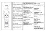
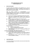
DIGITAL
MULTIMETER
MODEL - 5040 / 5040-T
AUTO
0
5000
1
2
3
4
A
5
5040
SELECT
RANGE
HOLD H
Hz
A
W
mA
m
A
OFF
mV
V
V
OFF
Optical RS232
A
mA m
A COM
MAX
10A
HBC FUSED
MAX 0.5A
HBC FUSED
W
V
MAX
1000V CAT III
600V CAT IV
TABLE OF CONTENTS
TITLE
OVERVIEW
PAGE
Overview............................................................. 01
Unpacking Inspection ..........................................02
SPECIFICATIONS
General Specifications........................................ 03
Electrical Specifications....................................... 05
Rules for Safe Operation...................................... 10
Safety ................................................................. 12
WARNING
To avoid electric shock or personal injury, read
the “Safety Information” and “Rules for Safe
Operation” carefully before using the Meter.
Digital Multimeter Model - 5040 / 5040-T (hereafter
referred to as “the Meter”) is a 3-4/5 digits
Multimeter with steady operations, and highly
reliable hand-held measuring instrument having
high degree of protection. The Multimeter not only
can measure AC / DC Voltage, AC / DC Current,
Resistance, Capacitance, Frequency, Diode Test,
but also has Data Hold, Full Icon Display, Backlight
Display.
International Electrical Symbols.......................... 14
The Multimeter Structure .................................... 15
The above instrument comes with a windows
software to record online data.
Measurement Operation......................................18
Functional Buttons.............................................. 23
Maintenance....................................................... 25
Replacing the Battery.......................................... 26
Test Certificate ................................................... 27
Warranty.............................................................. 28
TERMS IN THIS MANUAL
WARNING
Identifies conditions and actions that could result
in serious injury or even death to the user.
CAUTION
Identifies conditions and actions that could cause
damage or malfunction in the instrument.
1
Unpacking Inspection
Open the package case and take out the Multimeter.
Check the following items carefully to see any
missing or damaged part :
Item
Description
Qty.
1
English Operating Manual
1 piece
2
Test Lead
1 pair
3
Windows Software (Optional)
1 CD
4
Optical Cable (Optional)
1 no.
In the event you find any Part missing or damaged,
please contact your dealer immediately.
Item (3) & (4) are optional.
SPECIFICATIONS :
GENERAL SPECIFICATIONS :
Display :3-4/5 digits 5000 counts LCD display
Update rate :
52 Segments Bargraph : 60 per second nominal
Digital Data : 5 per second nominal;
Low Battery : Below approx. 7V
Operating Temperature : 0°C to 35°C, 0-80% R.H.;
35°C to 50°C, 0-70% R.H.
Storage Temperature :
-20°C to 60°C, 80% R.H. (with battery removed)
Temperature Coefficient : normal 0.15 x
(specified accuracy)/°C @ (0°C-18° or 28°C-50°C),
or otherwise specified.
Power Supply :Single standard Alkaline 9V battery
APO Timing :Idle for 17 minutes
Safety :
Double insulation per IEC61010-1 2nd Ed.,
EN61010-1 2nd Ed., UL61010-1 2nd Ed. &
CAN/CSA C22.2 No. 61010.1-0.92 to Category III
1000V AC & DC & Category IV 600V AC & DC.
Terminals (to COM) measurement Category :
V
: Category III 1000V AC & DC &
Category IV 600V AC & DC
A/mAm
A : Category III & Category IV 600V AC &
300V DC.
Transient Protection : 8kV (1.2/50m
s surge)
E.M.C. : Meets EN61326-1:2006 (EN55022,
EN61000-3-2, EN61000-3-3, EN61000-4-2,
EN61000-4-3, EN61000-4-4, EN61000-4-5,
EN61000-4-6, EN61000-4-8, EN61000-4-11)
2
3
In an RF field of 3V/m :
Capacitance function is not specified
Other function range :
Total Accuracy = Specified Accuracy + 100 digits
Performance above 3V/m is not specified.
ELECTRICAL SPECIFICATION
Accuracy is ± (% reading digits + number of digits)
or otherwise specified, at 23°C ± 5°C and less than
75% R.H
AC VOLTAGE (50Hz - 60Hz)
Overload Protections :
m
A&mA
A
V
mV
: 1A/600V, IR 10kA or better, F fuse;
: 10A/600V, IR 100kA or better, F fuse
: 1050Vrms, 1450Vpeak;
: 600VDC/VAC rms
W
& Others: 600VDC/VAC rms
Power Consumption : 4.3 mA typical
Dimension :(L)186mm X (W) 87mm X (H) 35.5mm;
(L)198mm X (W) 97mm X (H) 55mm with holster
Weight : 340gm; 430gm with holster
Special Feature :
Data Hold; Range Hold, Backlighted display;
Audible & visible input warning.
Accessories : Test leads pair, Holster, Battery
installed, User’s manual, PC interface kit (RS232
Optical adapter cable + RS232 software CD
Optional).
Range
50 mV
500 mV
5
V
50
V
500 V
1000 V
Resolution
10
m
V
100
m
V
1
10
100
1
mV
mV
mV
V
Accuracy
±(0.5%rdg+3dgts)
CMRR : >60dB @ DC to 60Hz, Rs =1kW
Input Impedance : 10MW
, 16pF nominal
(44pF nominal for 50mV & 500mV ranges)
AC VOLTAGE (40Hz - 500Hz)
Range
Resolution
Accuracy
10
m
V
50 mV
±(0.8%rdg+3dgts)
100
m
V
500 mV
5
V
1
mV
±(1.0%rdg+4dgts)
50
V
10
mV
500 V
100 mV
±(1.2%rdg+4dgts)
1000 V
1
V
CMRR : >60dB @ DC to 60Hz, Rs =1kW
Input Impedance : 10MW
, 16pF nominal
(44pF nominal for 50mV & 500mV ranges)
4
5
AC CURRENT (50Hz - 60Hz)
AC VOLTAGE (Upto 20kHz)
Range
50 mV
500 mV
5
V
50
V
500 V
1000 V
Resolution
10
m
V
100
m
V
1
10
100
1
mV
mV
mV
V
Accuracy
0.5 db*
3 db*
Unspec’d
Range
Resolution
Accuracy
500 m
A
100
nA
5000m
A
1
m
A
±(0.6%rdg+3dgts)
10
m
A
50 mA
100
m
A
±(1.0%rdg+3dgts)
500 mA
5
10
A
A*
1
10
mA
mA
±(0.6%rdg+3dgts)
*Specified from 30% to 100% of range
CMRR : >60dB @ DC to 60Hz, Rs=1kW
Input Impedance : 10MW
, 16pF nominal
(44pF nominal for 50mV & 500mV ranges)
Burden Voltage : 0.15mV/m
A for 500m
A, 5000m
A.
3.3mV/mA for 50mA, 500mA & 45mV/A for 5A,10A.
* 10A continuous, >10A to 15A for 30 seconds max
with 5 minutes cool down interval.
DC VOLTAGE
Range
Resolution
Accuracy
10
±(0.12%rdg+2dgts)
m
V
50 mV
100
m
V
500 mV
±(0.06%rdg+2dgts)
5
V
1
mV
50
V
10
mV
±(0.08%rdg+2dgts)
500 V
100 mV
1000 V
1
V
AC CURRENT (40Hz - 1kHz)
NMRR : >60dB @ 50/60Hz
CMRR : >120dB @ DC, 50/60Hz, Rs =1kW
Input Impedance : 10MW
, 16pF nominal
(44pF nominal for 50mV & 500mV ranges)
Burden Voltage : 0.15mV/m
A for 500m
A, 5000m
A
3.3mV/mA for 50mA, 500mA & 45mV/A for 5A,10A.
* 10A continuous, >10A to 15A for 30 seconds max
with 5 minutes cool down interval.
6
Range
Resolution
Accuracy
500 m
A
100
nA
5000m
A
1
m
A
±(0.8%rdg+4dgts)
10
m
A
50 mA
100
m
A
±(1.0%rdg+4dgts)
500 mA
5
10
A
A*
1
10
mA
mA
7
±(0.8%rdg+4dgts)
CAPACITANCE
DC CURRENT
Range
Resolution
Accuracy
500 m
A
100
nA
5000m
A
1
m
A
10
m
A
50 mA
±(0.2%rdg+4dgts)
100
m
A
500 mA
5
10
A
A*
1
10
mA
mA
Range
50
500
5
50
500
9999
Resolution
nF
0.01
nF
0.1
m
F
0.001
m
F
0.01
m
F** 0.1
m
F** 1
Accuracy*
nF
+(0.8%rdg+3dgts)
nF
m
F
+(1.5%rdg+3dgts)
m
F
+(2.5%rdg+3dgts)
m
F
+(3.5%rdg+5dgts)
m
F
+(5.0%rdg+5dgts)
Burden Voltage : 0.15mV/m
A for 500m
A, 5000m
A
3.3mV/mA for 50mA, 500mA & 45mV/A for 5A,10A.
* 10A continuous, >10A to 15A for 30 seconds max
with 5 minutes cool down interval.
* Accuracies with film capacitor or better.
**In manual-ranging mode, measurements not
specified below 45.0m
F and 450m
F for 500.0m
F
& 9999m
F ranges respectively.
RESISTANCE
FREQUENCY
Range
50
500
5
50
500
5
50
Resolution
Accuracy
+(0.3%rdg+6dgts)
W
0.01 W
+(0.1%rdg+3dgts)
W
0.1
W
W
KW
1
+(0.1%rdg+2dgts)
W
KW
10
W
KW
100
+(0.4%rdg+3dgts)
MW
1
KW
+(1.5%rdg+5dgts)
MW
10 KW
Open Circuit Voltage :
<1.3V DC (< 3V DC for 50W
& 500W
ranges)
Function
Sensitivity
(Sine RMS)
mV
5
V
50
V
500
V
1000 V
W
, Cx, Diode
m
A, mA, A
300 mV
2
V
20
V
80
V
300
V
300 mV
10% F.S.
Range
10Hz - 125 kHz
10Hz - 20 kHz
10Hz - 1
kHz
10Hz - 125 kHz
Accuracy : 0.01% rdg + 2 dgts
DIODE TEST
AUDIBLE CONTINUITY TESTER
Audible threshold
between 20W
and 200W
Response time
<100m
s
8
Range
2.000 V
Test Current
0.4mA
Accuracy
±(1.0%rdg+1dgt)
Open Circuit Voltage : <3.5V DC
Overload Protection : 600V DC or AC rms
9
RULES FOR SAFE OPERATION (1)
! Warning
To avoid possible electric shock or personal
injury, and to avoid possible damage to the
Meter or to the equipment under test, adhere to
the following rules :
?
Before using the Meter inspect the case. Do
not use the Meter if it is damaged or the case
(or part of the case) is removed. Look for cracks
or missing plastic. Pay attention to the insulation
around the connectors.
?
Inspect the test leads for damaged insulation or
exposed metal. Check the test leads for
Continuity. Replace damaged test leads with
identical electrical specifications before using
the Meter.
?
Do not apply more than the rated voltage, as
marked on the Meter, between the terminals or
between any terminal and grounding.
?
The rotary switch should be placed in the right
position and no any change over of range shall
bemade while measurement is conducted to
prevent damage of the Meter.
?
When measurement is taken at an effective
Voltage over 60V in DC or 30V rms in AC,
special care should be taken for there is danger
of electric shock.
?
Do not measure any circuit that draws more than
the current rating of the protection fuse.
?
Never attempt a voltage measurement with the
test lead inserted into the m
A/mA or A input jack.
?
Replace the blown fuse with the proper rating as
specified in the manual.
?
Use the proper terminals, function, and range for
your measurements.
?
Do not use or store the Meter in an environment
of high temperature, humidity, explosive,
inflammable and strong magnetic field. The
performance of the Meter may deteriorate after
the meter is dampened.
?
When using the test leads, keep your fingers
behind the finger guards.
RULES FOR SAFE OPERATION (2)
?
Disconnect circuit power and discharge all highvoltage capacitors before testing resistance,
continuity, diodes, or current.
?
Replace the battery as soon as the battery
Indicator
appears. With a low battery, the
Meter might produce false readings that can lead
to electric shock and personal injury.
?
Turn the Meter power off when it is not in use &
take out the battery when not using for a long
time.
?
Constantly check the battery as it may leak when
it has not been used for some time, replace the
battery as soon as leaking appears. A leaking
battery will damage the Meter.
?
Do not attempt a current measurement where
the open circuit voltage is above the protection
fuse voltage rating.
?
Disconnect the test leads from the test points
before changing functions. Always set the
instrument to the highest range and work down
ward for an unknown value if you are using
manual ranging mode.
10
11
OVERVOLTAGE CATEGORY II
Safety
This manual contains information and warnings
that must be followed for operating the instrument
safely and maintaining the instrument in a safe
operating condition. If the instrument is used in a
manner not specified by the manufacture, the
protection provided by the instruement may be
impaired.
The meter protection rating, against the users, is
Double insulation per IEC61010-1 2nd Ed.,
EN61010-1 2nd Ed., UL61010-1 2nd Ed. &
CAN/CSA C22.2 No. 61010.1-0.92 to Category III
1000V AC & DC & Category IV 600V AC & DC.
Terminals (to COM) measurement Category :
V
: Category III 1000V AC & DC &
Category IV 600V AC & DC
A/mAm
A : Category III & Category IV 600V AC &
300V DC.
Equipment of OVERVOLTAGE CATEGORY II is
energy consuming equipment to be supplied from
the fixed installation.
OVERVOLTAGE CATEGORY III
Equipment of OVERVOLTAGE CATEGORY III is
equipment in fixed installations.
Note - Examples include switches in the fixed
installations and some equipment for industrial
use with permanent connection to the fixed
installation.
OVERVOLTAGE CATEGORY IV
Equipment of OVERVOLTAGE CATEGORY IV is
for use at the origin of the installation.
Note - Examples include electricity meters and
primary over-current protection equipment.
Electromagnetic Compatibility (EMC)
Per IEC1010 Overvoltage Installation Category
The instrument Meets EN61326-1:2006 (EN55022,
EN61000-3-2, EN61000-3-3, EN61000-4-2,
OVERVOLTAGE CATEGORY I
EN61000-4-3, EN61000-4-4, EN61000-4-5,
Equipment of OVERVOLTAGE CATEGORY I is
equipment for connection to circuits in which
measures are taken to limit the transient overvoltages to an appropriate low level.
Note - Examples include protected electronic
circuits.
EN61000-4-6, EN61000-4-8, EN61000-4-11).
12
13
International Electrical Symbols
MULTIMETER STRUCTURE
Panel Illustration.
Grounding.
AUTO
Double Insulated.
0
5000
1
2
3
4
A
1
5
Fuse.
!
5040
Warning ! Refer to the Operating Manual.
Caution ! Risk of Electric Shock.
8
SELECT
RANGE
HOLD H
Hz
2
A
W
mA
m
A
OFF
mV
V
3
V
OFF
Optical RS232
A
mA m
A COM
MAX
10A
HBC FUSED
MAX 0.5A
HBC FUSED
4
W
V
MAX
1000V CAT III
600V CAT IV
7
5
6
1) 3-4/5 digits 5000 counts LCD display.
2) Push-buttons for special functions & features.
3) Selector to turn the Power On or Off and
Select a function
4) Input Jack for 10A (>10A to 15A for 30sec)
current function.
5) Input Jack for all functions EXCEPT current
(m
A, mA, A) functions.
6) Common (Ground reference) Input Jack for
all functions
7) Input Jack for milli-amp & micro-amp current
Functions.
8) Optical cable to connect DMM 5040 /
5040-T to PC.
14
15
Analog bar-graph
Crest Factor
The analog bar graph provides a visual indication of
measurement like a traditional analog meter needle. It
is excellent in detecting faulty contacts, identifying
potentiometer clicks, and indicating signal spikes
during adjustments.
Average sensing RMS Calibrated
RMS (Root-Mean-Square) is the term used to
describe the effective or equivalent DC value of an
AC signal. Most digital multimeters use average
sensing RMS calibrated technique to measure
RMS values of AC signals. The technique is to
obtain the average value by rectifying and filtering
the AC signal. The average value is then scaled
upward (calibrated) to read the RMS value of a
sine wave. In measuring pure sinusoidal
waveform, this technique is fast, accurate, and
cost effective. In measuring pure sinusoidal waveforms, however, significant errors can be
introduced because of different scaling factors
relating average to RMS values.
True RMS
True RMS is a term which identifies a DMM that
responds accurately to the effective RMS value
regardless of the waveforms such as : square,
sawtooth, triangle, pulse trains, spikes, as well as
distorted waveforms with the presences of
harmonics.
Harmonics may cause :
1) Overheated transformers, generators and motors
to burn out faster than normal.
2) Circuit breakers to trip prematurely.
3) Fuses to blow
4) Neutrals to overheat due to the triplen harmonics
present on the neutral.
5) Bus bars and electrical panels to vibrate.
16
Crest Factor is the ratio of the Crest (instantaneous
peak) value to the True RMS value, and is
commonly used to define the dynamic range of a
true RMS DMM. A pure sinusodial waveform has a
Crest Factor of 1.4. A badly distorted sinusoidal
waveform normally has a much higher Crest Factor.
NMRR (Normal Mode Rejection Ratio)
NMRR is the DMM’s ability to reject unwanted AC
noise effect which can cause inaccurate DC
measurements. NMRR is typically specified in
terms of dB (decibel). DMM 5040 / 5040-T has a
NMRR specification of >60dB at 50 and 60Hz
which means a good ability to reject the effect of
AC noise in DC measurements.
CMRR (Common Mode Rejection Ratio)
Common mode voltage is voltage present on both
the COM and VOLTAGE input terminals of a DMM
with respect to ground. CMRR is the DMM’s ability
to reject common mode voltage effect which can
cause digit rattle or offset in voltage measurements.
DMM 5040 / 5040-T has a CMRR specifications of
>60dB at DC 60Hz in ACV function; and >120dB at
DC, 50 and 60Hz in DCV function. If neither NMRR
nor CMRR specification is specified, a DMM’s
performance will be uncertain.
17
B)
MEASUREMENT OPERATION
A) DC Voltage, AC Voltage, Hz Frequency
functions mV function defaults at DC.
Press SELECT button momentarily to select AC.
Press the Hz push button momentarily to activate
and to exit Hz.
DCV
ACV
Hz
Capacitance
Diode test function
Default at
Press SELECT button
momentarily to select
Diode test function.
Caution
Discharge capacitors before making any
measurement. Large value capacitors should
be discharged through an appropriate
resistance load.
Diode
Diode
Note :
input sensitivity varies automatically with function
range selected before activating the Hz function.
mV function has the highest (300mV) & the 1000V
range has the lowest (300V). It is recommended to
first measure the signal voltage (or current) level
then activate the Hz function in that voltage (or
current) range to automatically set the most
appropriate trigger level. You can also press the
RANGE button momentarily to select another trigger
level manually. If the Hz reading becomes unstable,
select lower sensitivity to avoid electrical noise. If
the reading shows zero, select higher sensitivity.
Normal forward voltage drop (forward biased) for a
good silicon diode is between 0.400V to 0.900V. A
reading higher than that indicates a leaky diode
(defective). A zero reading indicates shorted diode
(defective). An OL indicates an open diode
(defective). Reverse the test leads connections
(reverse biased) across the diode. The display
shows OL if the diode is good. Any other readings
indicate the diode is resistive or shorted (defective).
18
19
Forward
Bias
Reverse
Bias
C) Resistance, Continuity functions
Default at W
,Press SELECT button
momentarily to select
Continuity function
which is convenient for checking wiring
connections and operation of switches. A
continuous beep tone indicates a complete
wire.
W
Auto leads resistance calibration
When entering the 50W
range manually by RANGE
button for high precision low resistance measurement, this feature will prompt you to short the
inputs for calibration. The display shows “Shrt”.
Simply short the leads for about 3 seconds until the
display shows zero, then the resistance in the leads
and in the internal protection circuitry of the meter
is compensated automatically. The compensation
value can be as much as 5W
W
W
3 sec.
D) m
A, mA and A Current function
Caution
Using resistance and continuity function in a live
circuit will produce false results and may damage
the instrument. In many cases the suspected
component must be disconnected from the circuit
to obtain an accurate reading.
20
Default at DC. Press SELECT button
momentarily to select AC.
* Note : When measuring a 3-phase system,
Sepecial attention should be taken to the phase
to phase voltage which is significantly higher
than the phase to earth voltage.
21
To avoid exceeding the voltage rating of the
FUNCTIONAL BUTTONS
protection fuse(s) accidentlly, always consider the
phase to phase voltage as the working voltage for
the protection fuse(s).
A
mA m
A
Backlighted display
Press the SELECT button for 1 second or more to
turn on and off the display backlight function. The
backlight will also be turned off automatically after
30 second to extend battery life.
+
+
E) RS232 PC computer interface capabilities
The instrument equips with an optical isolated
interface port at the meter back for data
communication. PC interface kit (RS232
optical adapter cable + RS232C software
floppies) is required to connect the meter to the
PC computer. The RS232 Data Recording
System software equips with a digital meter, an
analog meter, a comparator meter, and a Data
Graphical recorder display. Refer to the
README file in the interface kit for further
Details.
22
Hold H
The Hold function freezes the display for later view.
Press the HOLD button momentarily to activate and
to exit the hold function.
HOLD H
21
23
Mannual or Auto-ranging
Press the RANGE button momentarily to select
manual-ranging and the meter will remain in the
range it was in, the LCD annunciators AUTO turns
off. Press the button momentarily again to step
through the ranges. Press and hold the button for 1
second or more to resume auto-ranging.
Note :
Manual ranging feature is not available in Hz
function.
MAINTENANCE
! Warning
To avoid electrical shock, disconnect the meter
from any circuit, remove the test leads from the
input jacks and turn OFF the meter before opening
the case. Do not operate with open case. Install
only the same type of fuse or equivalent.
Cleaning and storage
Set Beeper Off
Press the Hz button while turning the meter on to
disable the Beeper feature.
Auto Power Off (APO)
The Auto Power Off (APO) mode turns the meter off
automatically to extend battery life after
approximately 17 minutes of no activities. Activites
are speciafied as : 1) Rotary switch or push button
operations and 2) Significant measuring data
readings of around 10% of range. That is, the meter
will intelligently avoid entering the APO mode when it
is under normal measurements. To wake up the
meter from APO, press the SELECT button
momentarily or turn the rotary switch to the OFF
position and then turn back on again. Always turn the
rotary switch to the OFF position when the meter is
not in use.
Periodically wipe the case with a damp cloth and
mild detergent; do not use abrasives or solvents.
If the meter is not to be used for periods of longer
than 60 days, remove the battery and store it
separately
Trouble Shooting
If the instrument fails to operate, check battery,
fuses, leads, etc., and replace as necessary.
Double check operating procedure as described in
this user’s manual.
Press the RANGE button while turning the meter on
to disable the Auto Power Off (APO) feature.
If the instrument voltage-resistance input terminal
has been subjected to high voltage transient
(caused by lighting or switching surge to the
system) by accident or abnormal conditions of
operation, the series fusible resistors will be blown
off (become high impedance) like fuses to protect
the user and the instrument. Most measuring
functions through this terminal will then be open
circuit. Refer to the warranty section for obtaining
warranty and repairing service.
24
25
Disabling Auto Power Off
Battery and Fuse replacement
The meter uses a single standard 9V battery, a
600V/1A IR 10kA fast acting F fuse (FS 1) for
m
A/mA current input, and a 600V/10A IR 100kA
fast acting F fuse (FS-2) for A current input.
Loosen the screws form the case buttom. Lift the
end of the case bottom nearest the input jacks until
it unsnaps from the case top. Replace the battery
and the blown fuse(s). Replace the case bottom,
and ensure that all the gaskets are properly seated
and the two snaps on the case top (near the LCD
side) are engaged. Re-fasten the screws.
MUMBAI
TEST CERTIFICATE
DIGITAL MULTIMETER
This Test Certificate warrantees that
the product has been inspected and
tested in accordance with the published
specifications.
The instrument has been calibrated by
using equipment which has already
been calibrated to standards traceable
to national standards.
5040 / 5040-T
MODEL NO. ________________
SERIAL NO. ___________
DATE: ___________
ISO 9001
REGISTERED
26
27
QC
KUSAM-MECO
PASS
WARRANTY
Each “KUSAM-MECO” product is warranted to be
free from defects in material and workmanship
under normal use & service. The warranty period is
Two years (24 months) and begins from the date of
despatch of goods. In case any defect occurs in
functioning of the instrument, under proper use,
within the warranty period, the same will be
rectified by us free of charges, provided the to and
fro freight charges are borne by you.
This warranty extends only to the original buyer or
end-user customer of a “KUSAM-MECO” authorized
dealer.
THIS WARRANTY IS BUYER’S SOLE AND
EXCLUSIVE REMEDY AND IS IN LIEU OF ALL
OTHER WARRANTIES, EXPRESS OR IMPLIED,
INCLUDING BUT NOT LIMITED TO ANY IMPLIED
WARRANTY OF MERCHANTABILITY OR
FITNESS FOR A PARTICULAR PURPOSE.
“KUSAM-MECO” SHALL NOT BE LIABLE FOR
ANY SPECIAL, INDIRECT, INCIDENTAL OR
CONSEQUENTIAL DAMAGES OR LOSSES,
INCLUDING LOSS OF DATA, ARISING FROM
ANY CAUSE WHATSOEVER.
All transaction are subject to Mumbai Jurisdiction.
This warranty does not apply for damaged Ic’s, fuses,
burnt PCB's, disposable batteries, carrying case,
test leads, or to any product which in “KUSAMMECO’s” opinion, has been misused, altered,
neglected, contaminated or damaged by accident or
abnormal conditions of operation or handling.
“KUSAM-MECO” authorized dealer shall extend this
warranty on new and unused products to end-user
customers only but have no authority to extend a
greater or different warranty on behalf of “KUSAMMECO”.
“KUSAM-MECO’s” warranty obligation is limited, at
option, free of charge repair, or replacement of a
defective product which is returned to a “KUSAMMECO” authorized service center within the
warranty period.
28
G 17,Bharat Industrial Estate, T. J. Road,
Sewree (W), Mumbai - 400 015. INDIA.
Sales Direct : (022) 24156638
Tel. : (022) 24124540, 24181649.
Fax : (022) 24149659
Email : [email protected]
Website : www.kusamelectrical.com,
www.kusam-meco.co.in
29