1
CHAPTER 3 CPU ARCHITECTURE
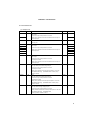
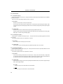
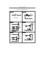
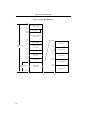
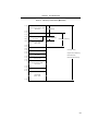
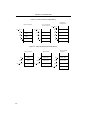
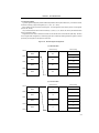
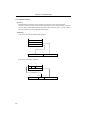
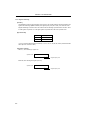
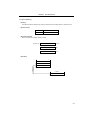
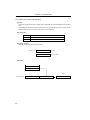
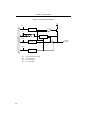
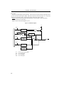
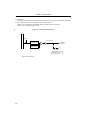
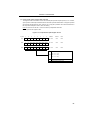
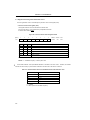
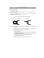
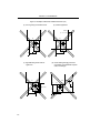
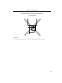
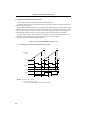
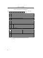
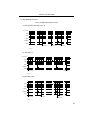
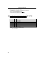
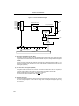
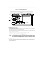
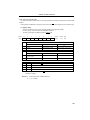
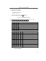
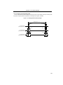
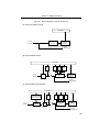
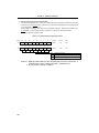
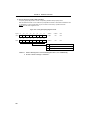
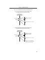
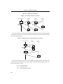
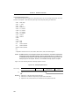
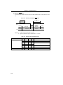
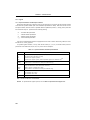
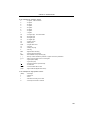
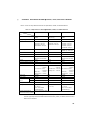
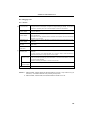
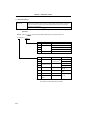
Figure 3-10. Data to be Saved to Stack Memory
Interrupt and
BRK Instruction
CALL, CALLF, and
CALLT Instruction
PUSH rp Instruction
SP
SP
SP
SP – 2
SP – 2
SP – 3
SP – 3
PC7 to PC0
SP – 2
Register Pair
Lower
SP – 2
PC7 to PC0
SP – 2
PC15 to PC8
SP – 1
Register Pair
Upper
SP – 1
PC15 to PC8
SP – 1
PSW
SP
SP
SP
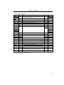
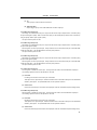
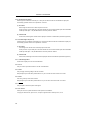
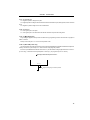
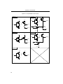
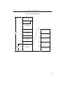
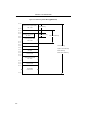
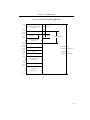
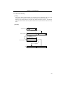
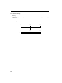
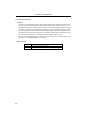
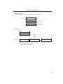
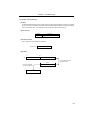
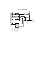
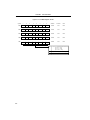
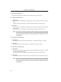
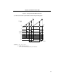
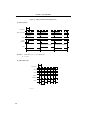
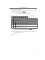
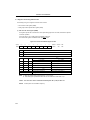
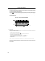
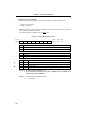
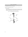
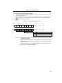
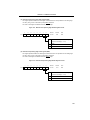
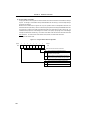
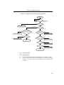
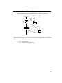
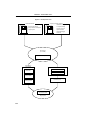
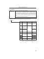
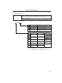
Figure 3-11. Data to be Restored from Stack Memory
POP rp Instruction
SP
RETI and RETB
Instruction
RET Instruction
SP
Register Pair
Lower
SP
PC7 to PC0
SP
PC7 to PC0
SP + 1
Register Pair
Upper
SP + 1
PC15 to PC8
SP + 1
PC15 to PC8
SP + 2
PSW
SP + 2
SP
SP + 2
SP
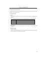
30
SP + 3