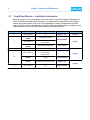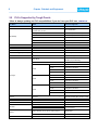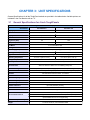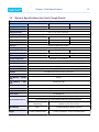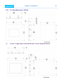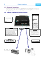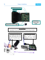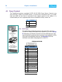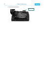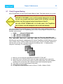
1
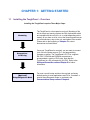
Hardware User Manual (Manual Part Number MAN-UTIC-P, Revision 1) ii WARNING! Programmable control devices such as the ToughPanel must not be used as stand-alone protection in any application. Unless proper safeguards are used, unwanted start-ups could result in equipment damage or personal injury. The operator must be made aware of this hazard and appropriate precautions must be taken. In addition, consideration must be given to the use of an emergency stop function that is independent of the programmable controller. The diagrams and examples in this user manual are included for illustrative purposes only. The manufacturer cannot assume responsibility or liability for actual use based on the diagrams and examples. WARNING: If the ToughPanel is used in a CLASS I, DIV. 2 environment, the following conditions must be met: Class I, Div. 2 methods; AND — must conform to all rules and requirements of applicable jurisdictions regarding Class I, Div. 2 installations; ALSO — peripheral equipment controlling this device or being controlled by it shall be suitable for service in the location in which they are used. Failure to comply with any of the above installation requirements will invalidate the device’s qualifications for service in CLASS I, DIV. 2 hazardous locations. WARNING: EXPLOSION HAZARD — SUBSTITUTION OF COMPONENTS MAY IMPAIR SUITABILITY FOR CLASS I, DIVISION 2. WARNING: EXPLOSION HAZARD — DO NOT DISCONNECT EQUIPMENT UNLESS POWER HAS BEEN SWITCHED OFF OR THE AREA IS KNOWN TO BE NON-HAZARDOUS. CAUTION Do not press the ToughPanel touchscreen with any sharp objects. This practice may damage the unit beyond repair. Trademarks This publication may contain references to products produced and/or offered by other companies. The product and company names may be trademarked and are the sole property of their respective owners. UTICOR Technology, L. P. disclaims any proprietary interest in the marks and names of others. Manual P/N MAN-UTIC-P, Revision 1, 08/08 © Copyright 2008, UTICOR Technology, L.P. All Rights Reserved No part of this manual shall be copied, reproduced, or transmitted in any way without the prior written consent of UTICOR Technology, L.P. UTICOR Technology, L.P. retains the exclusive rights to all information included in this document. MANUFACTURED and MARKETED by UTICOR TECHNOLOGY, L. P. 4140 Utica Ridge Rd. • Bettendorf, IA 52722-1327 Phone: 1-563-359-7501 • Fax: 1-563-359-9094 • www.UTICOR.net iii EU Compliance Information The ToughPanel is manufactured in compliance with European Union (EU) Directives and carries the CE mark. The ToughPanel has been tested under CE Test Standard #EN55011, and is listed under UL File #E209355. The following information is provided to comply with EU documentation requirements. Please NOTE: Products with CE marks perform their required functions safely and adhere to relevant standards as specified by EU directives provided they are used according to their intended purpose and that the instructions in this manual are adhered to. The protection provided by the equipment may be impaired if this equipment is not used in accordance with this manual. Only replacement parts supplied by UTICOR Technology, L.P. or its agents should be used. Technical Support If you need assistance, please call our technical support at 1-800-832-3647 or FAX us at 1-563-359-9094. SELV Circuits All electrical circuits connected to the communications port receptacle are rated as Safety Extra Low Voltage (SELV). Environmental Specifications Operating Temperature: 4" Monochrome 4" Color 6" White on Blue 6" Color 8" Color 10" Color 15" Color 0 to 40 °C 0 to 55 °C 0 to 45 °C 0 to 55 °C 0 to 40 °C 0 to 50 °C 0 to 45 °C Storage Temperature: All Models: –20 to +60 °C Operating Humidity: 10–95% R.H., non-condensing Air Composition: No corrosive gases permitted Preventative Maintenance and Cleaning: No preventative maintenance is required. The ToughPanel touchscreen should be cleaned as needed with warm, soapy water. Please refer to Chapter 5: Maintenance for a list of compatible/incompatible chemicals and compounds. iv Manual Revisions Manual Part Number : MAN-UTIC-P Revision 1 Manual Title : Tough Panel Hardware User Manual The following table provides you with updated information. If you call technical support with a question about this manual, please be aware of the revision number and date. Revision Author Date Effective Pages Description of Changes Original Release EG/ECF September, 2008 All Original Release of Manual v Manual Organization The information below provides an overall description of the topics covered within this manual. Chapter 1: Getting Started General overview of the installation procedure; lists all the equipment you need to get started. Explains how to get help with installation questions or problems you might encounter through On-screen Help and Technical Support. Chapter 2: Models and Equipment Overview of Uticor part numbering system. Quick reference chart of all ToughPanel models and the competitor units they replace, with internal document links for general specifications, dimensions, and panel cutout measurements. Lists the important features of all ToughPanels with dedicated processors, and the PLC drivers they support by brand, model, and protocol. Descriptions of replacement parts & optional accessories available, including memory cards, PLC cables, and the programming cable. Chapter 3: Specifications General specifications and detailed information are given for each model, such as weights, dimensions, and service power requirements; operating and storage temperatures; memory and serial communication options, etc. Chapter 4: Installation Overview of the physical requirements for mounting in a NEMA4 rated enclosure or cabinet. Instructions for mounting with DIN brackets. Provides dimensional diagrams and cutout measurements for each of the ToughPanel models. Identifies and defines all connectors on ToughPanel units. Tells you how to properly connect the unit to power supply, programming computer, printer, or a PLC. Shows the setup screens displayed after initial powerup of the panel. Describes each setup screen and how to use it to set up your panel. Chapter 5: Maintenance Provides instructions on battery replacement, gasket replacement, memory upgrade (FLASH and RAM), Fuse Reset, and fluorescent backlight replacement. Discusses precautions and cleaning necessary to ensure longevity of the panel. Chapter 6: Troubleshooting Aids in diagnosing problems you might encounter when installing or operating your ToughPanel. Provides steps to take to isolate and correct problems. Appendix A: Wiring diagrams for several PLC cables are provided. Appendix B: Option Card Installation instructions are provided. vi Table of Contents WARNING! EU Compliance Information Manual Revisions Manual Organization Chapter 1:Getting Started 1.1 Installing the ToughPanel – Overview 1.2 What You Need to Get Started 1.2.1 Hardware 1.2.2 Software 1.2.3 ToughPanel Manuals 1.3 Need Help? 1.3.1 On-screen Installation HELP 1.3.2 On-screen PLC HELP 1.3.3 Technical Support Chapter 2:Models and Equipment 2.1 Introduction to the Uticor ToughPanels 2.2 ToughPanel Part Numbering System 2.3 ToughPanel Models – Installation Information 2.4 ToughPanel Features – All Models 2.5 PLCs Supported by Tough Panels 2.5.1 Universal Ethernet Drivers 2.5.2 High Speed Dedicated Network Drivers 2.5.3 Dual Drivers 2.5.4 NetView & Control 2.6 Optional Parts and Accessories 2.6.1 Cables 2.6.2 Other Parts & Accessories Chapter 3:Unit Specifications 3.1 General Specifications for 4-inch ToughPanels 3.2 General Specifications for 6-inch Tough Panels 3.3 General Specifications for 8 and 10-inch Tough Panels 3.4 General Specifications for 10 and 15-inch ToughPanels Chapter 4:Installation 4.1 Mounting Overview 4.2 DIN Bracket Mounting – Step by Step 4.3 4-inch ToughPanel Dimensions and Cutout Measurements 4.4 6-inch ToughPanel Dimensions and Cutout Measurements 4.4.1 6” Panel dimensions: PV550, PV600, & QP 6” models 4.4.2 6” Panel dimensions: PV700 models 4.5 8-inch ToughPanel Dimensions and Cutout Measurements 4.6 10-inch ToughPanel Dimensions and Cutout Measurements 4.6.1 10” Panel Dimensions: PV900, PVPlus1000, & QP 10” series 4.6.2 10” Panel Dimensions: PV1000 4.6.3 10” Panel Dimensions: PV1200 4.7 15-inch ToughPanel Dimensions and Cutout Measurements 4.8 Wiring and Connections 4.8.1 Standard ToughPanel with Dedicated Processor ii iii iv v 1 1 2 2 2 2 3 3 3 3 4 4 5 6 7 8 9 9 9 9 10 10 11 12 12 13 14 15 16 16 17 18 18 18 19 19 20 20 20 21 21 22 22 vii 4.8.2 4-inch and smaller footprint 6-inch ToughPanels 25 4.9 Power Terminal 26 4.10 PLC Port 26 4.11 COM1 Port 27 4.12 Communications Setup 28 4.12.1 Setup Mode 28 4.12.2 Clock 28 4.12.3 COM1 29 4.12.4 Group & Unit 30 4.12.5 Contrast 30 4.12.6 Touchpad Test 31 4.12.7 Display Test 31 4.12.8 Entering & Exiting Setup Mode 31 Chapter 5:Maintenance 32 5.1 Shutting Off Power to ToughPanel 32 5.2 Program Backup to Disk 33 5.3 Lithium Battery Replacement 35 5.4 Panel Status Indicator Light 36 5.5 Gasket Replacement 36 5.6 RAM Upgrade 37 5.7 Flash Program Backup 39 5.8 Fuse Reset 40 5.9 Fluorescent Backlight Bulb Replacement 40 5.10 Precautions: 40 5.11 Touchscreen Chemical Compatibility 41 5.12 Touchscreen Cleaning 41 Chapter 6:Troubleshooting 42 6.1 Common Problems: 42 6.1.1 Problem: Panel won’t power up 42 6.1.2 Problem: Cannot communicate with ToughPanel from Programming Computer 42 6.1.3 Problem: Communications with PLC 42 6.1.4 Problem: Memory Card 43 6.1.5 Problem: Display Blank 43 6.1.6 Problem: Display hangs when unit is powered up, “Initializing...” message remains on screen (unit has invalid RAM memory) 43 6.2 Still Need Help? 44 6.2.1 Warranty Repairs 44 6.2.2 Out of Warranty Repairs 44 Appendix A:PLC Cable Wiring Diagrams 45 Appendix B:Option Card Installation 57 CHAPTER 1: GETTING STARTED 1.1 Installing the ToughPanel – Overview Installing the ToughPanel requires Three Major Steps: Mounting Connections & Wiring (Optional) Setup/Diagnostic Mode The ToughPanel is a front-panel mount unit. Mounting of the unit is simple and merely requires the DIN clip brackets which are included with the unit (four, six, or eight depending on the model). All you have to do is cut out the mounting-panel as per cut-out dimensions, drop in the unit, and tighten a few screws. Please refer to the beginning of Chapter 4 for cutout dimensions and instructions. Once your ToughPanel is mounted, you are ready to connect your unit to the power source, PLC, and programming computer or printer. The ToughPanel’s PLC Port supports RS-232C, RS-422A and RS-485A connections to accommodate a variety of PLC ports. Note that the ToughPanel is a DC powered unit (24 VDC). Refer to the Wiring and Connections section of Chapter 4 for further information. For most users this step would not be required, as factory defaults works for most applications and PLCs. If needed, a special Setup/Diagnostic mode is provided in the Communications Setup section of Chapter 4. 2 1.2 1.2.1 Chapter 1:Getting Started What You Need to Get Started Hardware 1.2.2 ToughPanel & enclosed mounting hardware (4, 6, or 8 DIN Clip Brackets, depending on size of ToughPanel model) 24 Volt Power Supply, RS-232C Programming Cable (P/N CBL-UTICW-009) PLC Interface Cable as required.(see Page 10 for part numbers specific to your PLC model), Ethernet cables as required PC requirements: IBM or compatible PC (Pentium or better) with a mouse and separate serial port (USB port may be used with a Serial to USB converter) Display with at least 800 x 600 resolution (1024 x 768 recommended) Standard Windows XP/Vista® operating system CD ROM Drive uWin08 Programming Software Software 1.2.3 ToughPanel uWin08 Software (P/N MAN-UTICW-CD) ToughPanel uWin08 Software User Manual (P/N MAN-UTIC-M) ToughPanel Manuals There are two manuals that you will need to use your ToughPanel; ToughPanel UTP Hardware User Manual (this manual) ToughPanel UTP uWin08 Software User Manual (P/N MAN-UTIC-M). This ToughPanel UTP Hardware User Manual will give you all the information necessary to install the ToughPanel in a fixed location in your work environment, and how to wire it to your PLC and to a programming device or network. Included are mounting diagrams for panel cutouts and instructions for installation with the enclosed DIN clip brackets, Connections and Wiring requirements, Panel Setup instructions, Maintenance Information, and Troubleshooting. Meanwhile, if you want to start designing your screens, you can do so off-line on a PC -- you can install uWin08, the ToughPanel Programming Software, on a computer and design your screen(s) without any connection to a ToughPanel. The screen designs can be downloaded to the ToughPanel afterward, before or after the physical installation of the hardware! To set up the screens, please consult the ToughPanel UTP uWin08 Software User Manual (P/N MAN-UTIC-M). Chapter 1:Getting Started 1.3 3 Need Help? Help is never more than a mouse click or a key press away! 1.3.1 On-screen Installation HELP In addition to this manual, Installation Guidelines and Diagrams can also be found in the HELP of uWin08, the ToughPanel Programming Software! To access these Help windows, click on "Help" in the Menu bar of the uWin08 Software, select "Help Topics", and then click on the "Contents" tab. One of the topics displayed will be "Hardware Installation", and it contains all the essential information needed, including dimensions, mounting instructions, connection and wiring setup, and more! 1.3.2 On-screen PLC HELP You can also consult the uWin08 Software HELP if you need help with the PLC to ToughPanel Interface, or any other communications or wiring issue. Each PLC Driver has a Help Topic that lists the error messages and provides an explanation for each. Also provided are PLC to ToughPanel wiring diagrams. 1.3.3 Technical Support Although most questions would be answered with this manual or the HELP within uWin08 Software, if you are still having difficulty with a particular aspect of installation or screen design, technical support is available at 1-800-TEC-ENGR (832-3647) or FAX us at 1-563-359-9094. You can also visit our website at www.uticor.net. CHAPTER 2: MODELS AND EQUIPMENT 2.1 Introduction to the Uticor ToughPanels The Uticor ToughPanel is a family of state-of-the art HMIs that combine all the latest advantages of digital control technology in a compact package designed to withstand the harshest of industrial environments. The ToughPanel family can be ordered with a wide variety of features, and in a number of sizes suited to fit any automation control application. Here is is a quick overview of some of the main features, followed by a chart showing all the ToughPanel possibilities as denoted by the Uticor Part Numbering system. The primary choices for ToughPanel models consist of: 1. 2. 3. 4. Choice of Operating System Size and, in some cases, Display Communications Options Choices of Bezel Material and Design Operating System: The ToughPanel has two choices for its operating system: a dedicated Uticor operating system or Windows CE operating system. The dedicated OS provides higher response speed and lower memory requirements. This Manual is for the Installation and setup of the ToughPanel dedicated processor model; please refer to the ToughPanel CE Hardware Manual for detailed information regarding the Installation and Setup of the ToughPanel Windows CE unit. Size & Type of Display: The standard (dedicated processor/OS) ToughPanel is available in a wide range of sizes and display options, including 4-inch, 6-inch, 8-inch, 10-inch, and 15-inch models with color TFT screens. In some of the smaller units, white-on-blue or monochrome screens are available. Additionally, a “High Bright” option is available for enhanced visibility in outdoor use. Communications: As a general rule, all ToughPanel models are equipped with a comprehensive package of serial drivers. The exception to this rule is that the Universal Ethernet models (6” PVP700 & larger) are manufactured with an Ethernet connector installed in the place of the 15-pin D-sub (PLC) serial port. Such a unit would come with only the Ethernet protocols. The smaller standard units (4” & smaller 6” models) have the option of being manufactured with Ethernet connectivity in addition to the serial ports, and with all the appropriate drivers & protocols to support programming & communication. In addition to the serial drivers and Universal Ethernet, there are a number of option cards available to connect your ToughPanel model to an industrial network or fieldbus system. Each industrial network has it's own option card, and only one option card can be added to the ToughPanel at a time. Bezel: Finally, the ToughPanel bezel is offered in either aluminum or stainless steel material. The stainless steel bezels are useful in applications involving food and drug manufacturing. Some of the ToughPanel sizes come with specially designed bezels so they can be used as quick, drop-in replacements for some of our competitors' models (see the reference chart on Page 6 for “Drop-in” replacement compatibilities). Thus, the ToughPanels can be used to replace hard-to-find competing units without any modifications to the existing mounting scheme. Uticor can also help users in converting their old programs to ToughPanel applications. Chapter 2:Models and Equipment 2.2 5 ToughPanel Part Numbering System UTX–XX XX–X–X[–XXXXXX][–X] 1 2 3 4 5 6 7 1 Choice of Operating System: P – for Dedicated/Proprietary C – for Windows CE (for these models, refer to the ToughPanel CE Hardware Manual) 2 Size of Display: 04 - 4" display, 06 – 6” 08 – 8” 10 – 10” 15 -- for 15” display 3 Type of Display: TC - for TFT Color WB - for White on Blue (6” PVP700 model only) MG - for Monochrome Gray (4” models only) 4 Optional Driver/NetView card: Available only on 4” & select 6” models: 0 – Standard unit, RS232 and RS422/485 serial ports & serial drivers only E – Ethernet option; supports programming and communications through Modbus TCP/IP, Ethernet I/P, Uticor TCP/IP, or GE SRTP protocols The following options available only on 6” PVP700 and 8-, 10-, & 15-inch models: 0 – Standard unit, RS232 and RS422/485 serial ports & serial drivers only C – Mitsubishi CCLink D – DeviceNet H – DH+ and Remote I/O M – Modbus Plus P – Profibus N – Netview-Control and Data storage U – Universal Ethernet: Ethernet Port replaces Serial Port (not applicable on Windows CE units) – supports programming and communications only through the Modbus TCP/IP, Ethernet I/P, Uticor TCP/IP, or GE SRTP protocols. All of these sizes and options – except “U” – offer all supported Serial PLC Drivers (see list on Pages 8 & 9). 5 Bezel Material: A – for Aluminum S – for Stainless Steel 6 Special Bezel (see the reference chart on next page for “Drop-in” replacement compatibilities): PV550K – for PanelView 550 with Keypad (6” Display Model) PVP700 – for PanelView Plus 700 Touch only (6” Display Model) PV1000 – for PanelView 1000 or 1000E Touch only (10” Display Model) PV1200 -- for PanelView 1200 (10” Display Model) 7 Visibility H – Indicates “High Bright” option for outdoor viewing 6 2.3 Chapter 2:Models and Equipment ToughPanel Models – Installation Information Below is a chart to use as a navigation tool in the manual. It provides important information on all the ToughPanel models broken down by the unit size (which is determined by the display screen) and model number. First is the unit compatibility as a drop-in replacement for older units, followed by links to the pages in this manual which give the dimensions and panel cutout measurements for each model, and each models general specifications. Model/Screen Size Model # Drop-in Replacement for: Dimensions Specifications 4” UTP-04TC-X-X n/a Page 18, Top Page 12 UTX-06TC-X-XPV550K Allen Bradley PV550 UTX-06TC-X-X Allen Bradley PV600; QP 6" series UTX-06TC-X-XPVP700 Allen Bradley PVPlus 700 Page 19,Top UTX-08TC-X-X QP 9" EL & Monochrome Page 19, Bottom Allen Bradley PV900 & PVPlus1000; QP 10" series Page 20, Top UTX-10TC-X-X UTX-10TC-X-XPV1000 Allen Bradley PV 1000 & PV 1000E Page 20, Bottom UTX-10TC-X-XPV1200 Allen Bradley PV 1200 12" CRT Page 21, Top UTX-15TC-X-X Allen Bradley PVPlus 1500 15" TFT 6” 8” 10” 15” Page 18, Bottom Page 13 Page 14 Page 15 Page 21, Bottom Chapter 2:Models and Equipment 2.4 7 ToughPanel Features – All Models Pre-built panel components for easy screen design including a number of special parts, such as: Toggle Switch, Slide Switch, Selector Switch, Throw Switch, Thumbwheel Object, Meters, PID Faceplates, and Analog/Digital Clock Flash based design for easy firmware upgrade and field expandable user RAM Nonvolatile flash card option for user program backup Color models support 128-color palette for components and bitmaps Multiple languages (up to 9) Two communications ports — Computer (RS-232C) and PLC (RS-232C, RS-422A, or RS-485A) Up to 999 screens Built-in clock and calendar or reference the PLC clock Built-in soft keypad for numeric and alphanumeric entry Password Protection for every touch object with passwords for up to 8 user groups 16 level undo and redo Import bitmaps Serial Printer support 40-character tag names to personally label PLC memory locations instead of cryptic PLC addresses Statistical Process Control (SPC) Exclusive Netview and Control Dual Drivers - Most PLC and Network Protocols supported Data Acquisition Complete NEMA 4, 4X Industrial Ratings Network and I/O Card Options Light Weight / Low Power 8 2.5 Chapter 2:Models and Equipment PLCs Supported by Tough Panels Uticor is always updating our PLC compatibilities; if you don't see your PLC here, contact us. PLC Brand Model Protocols Supported EZAutomation EZPLC EZ Protocol Micrologix 1000/1200/1500. SLC 500, 5/01, /02, /03 DH+ 485/AIC/AIC+ Micrologix 1000/1200/1500 DF1 Half Duplex, DF1 Full Duplex SLC5/03, 5/04, & 5/05 DF1 Half Duplex, DF1 Full Duplex SLC 5/04, PLC 5 DH+ (Option Card) PLC 5 DF1 PLC 2, 3, and 5 Remote I/O (w/DH+ Plus Option Card) Aromat Aromat Mewtocol COM Baldor Mint, Flex and MicroFlex drives Mint Host Comms RS-232/485 Protocols Control Techniques Unidrive 2-wire, 4-wire Binary Control Technology Corporation (CTC) CTC 2600, 2700, and 5100 CTC Binary DeviceNet DeviceNet I/O DeviceNet I/O (Option Card) DL05, DL06 K-Sequence, DirectNet; ModBus (Koyo Addressing) DL105 K-Sequence Allen Bradley DL205 DirectLogic DL305 DL405 D2-230 K-Sequence D2-240 K-Sequence; DirectNet D2-250/D2-250-1/260 K-Sequence; DirectNet D2-240/250 w/DCM DirectNet D3-330/330P DirectNet D3-340 DirectNet D3-350 K-Sequence; DirectNet D3-350 w/DCM DirectNet D4-430 K-Sequence; DirectNet D4-440 K-Sequence; DirectNet D4-450 K-Sequence; DirectNet; All with DCM DirectNet Ethernet Control Logic, Micro Logic, Compact Logic, GE Ethernet I/P, SRTP, DF1, Modbus TCP/IP Versamax General Electric 90/30 and 90/70 Versamax SNPX Idec Idec Computer Link FX Series (all) FX, Direct CC Link CC Link Protocol Mitsubishi Modicon Omron 984 CPU, Quantum 113 CPU AEG Modicon Micro Modbus RTU Series 110 CPU: 311-xx, 411-xx, 512-xx, 612-xx 984 Series, Quantum Series Modbus Plus (Option Card) C200, C500, CQM1, CPM1, CPM2 Host Link Chapter 2:Models and Equipment 9 PLC Brand Model Protocols Supported Parker Hannifan Gemini Series (GV, GT) Servo Drives ASCII RS-232/485 Siemens S7 MPI Adaptor 3964R Siemens S7_200 Siemens S7_200 Square D Symax 300 Series CPU, 400 Series CPU Symax Texas Instruments TI5x5 Series, TI505, TI545-1102, TI545-1104 TBP (Transparent Byte Protocol) or NITP (Non-Intelligent Terminal Protocol) Uni-Telway Telemecanique TSX 37 Micro UNI-TE (Version 1.1) Yaskawa n/a Memobus protocol Other H2 – WinPLC [Entivity (Think & Do) V5.2 or later Entivity (Think & Do) Siemens 2.5.1 Universal Ethernet Drivers All ToughPanel models can be modified for Ethernet connectivity by the addition or installation (depending on unit size) of the appropriate connector. The unit will then support the following software selectable Ethernet protocols: Allen-Bradley Control-Logix with Native Tags Allen-Bradley SLC or MicroLogix DF1 over Ethernet Modbus TCP/IP GE SRTP Profinet (coming soon) 2.5.2 High Speed Dedicated Network Drivers Optional network cards are available to expand the ToughPanel communications for each of the major industrial networks. All ToughPanel models require an expansion card to communicate with these networks, and each network requires it's own option card. The ToughPanel only accepts one network card at a time: DH+/Remote I/O (Rockwell) Modbus Plus (Schneider) DeviceNet CC-Link (Mitsubishi) Profibus 2.5.3 Dual Drivers Using an option card, ToughPanels have the ability to communicate to two PLCs simultaneously. For example, you can communicate to Profibus on the network side and DH485 or DF1 on the PLC side. 2.5.4 NetView & Control An additional feature that can be added to the ToughPanel is a NetView and Control option card, which uses an Ethernet connector. This provides Real-Time operation, monitoring, and editing of your ToughPanel from anywhere in the world over the Internet. This option can be configured to send you emails from the ToughPanel for operational updates, alarms, etc., and the circuit board has an SD card slot for an additional 2GB of data storage. 10 2.6 Chapter 2:Models and Equipment Optional Parts and Accessories There are replacement parts and other optional equipment available to customize or upgrade the Tough Panel to fit your application. The tables below provide you with a list of this equipment. Instructions, if necessary, on how to install this equipment to upgrade your unit are also provided. To order from these lists, phone UTICOR Technology, L. P. at 1-563-359-7501. 2.6.1 Cables Part Number CBL-UTICW-009 Part Number Description RS-232 Programming Cable (2m / 6.56 ft.) PLC Cables – All come in lengths of 3m (9.8 ft.): CBL-UTICW-001 GE 90/30 and 90/70 15-pin Dsub port (RS-422A) CBL-UTICW-002 A-B SLC 5/03/04/05 DF1 port (RS-232C) CBL-UTICW-003 A-B PLC5 DF1 port (RS-232C) CBL-UTICW-004 A-B SLC DH485 port (RS-485A) CBL-UTICW-005 A-B MicroLogix 1000,1200 & 1500 (RS-232C) CBL-UTICW-006 Mitsubishi FX Series 25-pin port (RS-422A) CBL-UTICW-007 Mitsubishi FX Series 8-pin MINI-DIN (RS-422A) CBL-UTICW-008 Omron C200, C500 (RS-232C) CBL-UTICW-010 ModBus with RJ45 (RS-232C) CBL-UTICW-011 Modicon ModBus (RS-232C) CBL-UTICW-012 Siemens S7 MPI Adaptor (RS-232C) CBL-UTICW-013 Omron 9-pin Programming Port (RS-232C) CBL-UTICW-014 GE Versmax (RS-232C) CBL-UTICW-016 Control Technics Unidrive 4-wire (RS-485A) CBL-UTICW-017 ontrol Technics Unidrive 2-wire (RS-485A) CBL-UTICW-019 Control Technology Corp phone type 6-position (RS-232C) CBL-UTICW-021 Uni-Telway Telemecanique TSX 37 Micro (RS-485A) CBL-UTICW-022 TI 505 Series 9-pin female (RS-232C) CBL-UTICW-023 TI 545-1102 Series 9-pin male (RS-422A) CBL-UTICW-024 TI 545-1104 Series 9-pin female (RS-422A) CBL-UTICW-025 Square D SYMAX 9-pin male (RS-422A) Chapter 2:Models and Equipment 2.6.2 Other Parts & Accessories Part Number Description ACC-UTICW-EDIT uWin08 ToughPanel Programming Software ACC-UTICW-512KF 512K Flash Upgrade ACC-UTICW-1MEGF 1 MEG Flash Upgrade ACC-UTICW-2MEGF 2 MEG Flash Upgrade ACC-UTICW-512KR 512K RAM Upgrade ACC-UTICW-1MEGR 1 MEG RAM Upgrade ACC-UTICW-BAT Replacement Battery ACC-UTICW-ADP15 RS-422 Terminal Block Adaptor (15 Pin) MBK-DCLIP-001 DIN Clip Mounting Bracket Replacement Gasket Replacement Gasket Replacement Gasket Replacement Gasket Replacement Gasket Replacement Gasket Replacement Gasket Replacement Gasket Option Card Option Card Option Card Option Card Option Card 11 CHAPTER 3: UNIT SPECIFICATIONS General Specifications for all the ToughPanel models are provided in the tables below. Variable options are indicated in the Part Number with an “X”. 3.1 General Specifications for 4-inch ToughPanels Uticor ToughPanel Jr. 3.8” & 3.5” display models Part Number: Display Specification Enclosure Display View Area UTP-04MG-X-X UTP-04TC-X-X 3.8” Monochrome 3.5” TFT Color NEMA 4/4X, Class I, Div II with FDA Compliance, Aluminum or Stainless Steel 3.14” x 2.39” (79.8 x 60.6mm) 320 x 240 Screen Pixels Brightness (Nits) Life (Hours) 2.87” x 2.18” (72.9 x 55.4mm) 140 400 50,000 75,000 Cell Matrix 8 x 6; 48 resistive cells CPU Type Motorola Coldfire 32-bit, 40 MHz Power Supply Required 24VDC (20-30VDC operating range), 1.5A switching Power @ 24 VDC (Watts) 12W Approvals UL, CUL, CE (Pending Only Part number change) Operating Temperature Storage Temperature Humidity Electrical Noise Withstand Voltage Insulation Resistance Vibration Shock User Memory – System RAM 15W 0° to 45° C (32° to 113° F) 0° to 55° C (32° to 131° F) -20° to 60° C (-4° to 140° F) 10 – 95% RH, relative humidity NEMA ICS 2-230 showering arc ANSI C37.90a-1974 SWC Level C Chattering Relay Test 1000VDC (1 minute), between power supply input terminal and protective ground (FG) Over 20 MΩ, between power supply input terminal and protective ground (FG) 5 to 55Hz 3G for 2 hours in the X, Y, & Z axes 20G for under 12 ms in the X, Y, & Z axes 512 KB User Memory – Exp. RAM none User Memory - Flash 1 MB Number of Screens Real Time Clock Screen Saver Up to 999, limited by memory None Yes; Backlight off PLC Port: RS-232/RS-422/RS-485 15-pin D-Sub (female) Serial Communications Download/Program Port: RS-232/RS-422/RS-485 9-pin D-Sub (female) Optional Ethernet for PLC or Programming Option Card Expandability Weight None 1.8 lbs for Aluminum, 2.6 for Stainless Steel Chapter 3:Unit Specifications 3.2 13 General Specifications for 6-inch Tough Panels Uticor ToughPanel 5.7” display model specifications Part Number: Display Specification UTP-06TC-X-X UTX-06WB-X-X-PV700 UTX-06TC-X-X-PV700 5.7” TFT Color 5.7” White on Blue 5.7” TFT Color NEMA 4/4X, Class I, Div II with FDA Compliance, Aluminum or Stainless Steel Enclosure 4.57” x 3.44” (116.2 x 87.4mm) Display View Area 320 x 240 Screen Pixels 400 140 400 Life (Hours) 75,000 50,000 75,000 Cell Matrix 16 x 12; 192 resistive cells 8 x 6; 48 resistive cells 16 x 12; 192 resistive cells Brightness (Nits) Motorola Coldfire 32-bit, 40 MHz CPU Type 24VDC (20-30VDC operating range), 1.5A switching Power Supply Required Power @ 24 VDC (Watts) 16W 12W UL, CUL, CE (Pending Only Part number change) Approvals Operating Temperature 0° to 55° C (32° to 131° F) 0° to 45° C (32° to 113° F) 0° to 55° C (32° to 131° F) -20° to 60° C (-4° to 140° F) Storage Temperature 10 – 95% RH, relative humidity Humidity NEMA ICS 2-230 showering arc, ANSI C37.90a-1974 SWC Level C Chattering Relay Test Electrical Noise 1000VDC (1 minute), between power supply input terminal and protective ground (FG) Withstand Voltage Insulation Resistance Over 20 MΩ, between power supply input terminal and protective ground (FG) 5 to 55Hz 3G for 2 hours in the X, Y, & Z axes Vibration 20G for under 12 ms in the X, Y, & Z axes Shock User Memory – System RAM User RAM 16W Memory – 512 KB Exp. 512 KB and 1 MB 1 MB & 2 MB Flash card for user program backup User Memory - Flash Up to 999, limited by memory Number of Screens Built into Panel (PLC clock is still accessible if available) Real Time Clock Yes; Backlight off Screen Saver PLC Port: RS-232/RS-422/RS-485 15-pin D-Sub (female) Serial Communications Option Expandability Weight Card Download/Program Port: RS-232/RS-422/RS-485 9-pin D-Sub (female) Optional Ethernet for PLC or Programming For Universal Ethernet models: Universal Ethernet Port replaces 15-pin D-sub connector None Industrial Networks, NetView & Control 2.3 lbs for Aluminum, 3.3 lbs for Stainless Steel 2.8 lbs. for Aluminum, 3.8 lbs. for Stainless Steel 14 3.3 Chapter 3:Unit Specifications General Specifications for 8 and 10-inch Tough Panels Uticor ToughPanel 8.2” & 10.4” display model specifications Part Number: UTP-08TC-X-X UTP-10TC-X-X UTX-10TC-X-X-PV1000 Display Specification 8.2” TFT Color Enclosure NEMA 4/4X, Class I, Div II with FDA Compliance, Aluminum or Stainless Steel Display View Area 10.4” TFT Color 6.73” x 5.10” (170.9 x 129.6mm) 8.31” x 6.22” (211.07 x 158mm) 640 x 480 Screen Pixels Brightness (Nits) Life (Hours) 330 370 54,000 50,000 Cell Matrix 16 x 12; 192 resistive cells CPU Type Motorola Coldfire 32-bit, 40 MHz 24VDC (20-30VDC operating range), 1.5A switching Power Supply Required Power @ 24 VDC (Watts) Approvals 18W 18W UL, CUL, CE (Pending Only Part number change) 0° to 55° C (32° to 131° F) Operating Temperature -20° to 60° C (-4° to 140° F) Storage Temperature 10 – 95% RH, relative humidity Humidity Electrical Noise Withstand Voltage Insulation Resistance Vibration Shock NEMA ICS 2-230 showering arc, ANSI C37.90a-1974 SWC Level C Chattering Relay Test 1000VDC (1 minute), between power supply input terminal and protective ground (FG) Over 20 MΩ, between power supply input terminal and protective ground (FG) 5 to 55Hz 3G for 2 hours in the X, Y, & Z axes 20G for under 12 ms in the X, Y, & Z axes User Memory – System RAM 512 KB 512 KB and 1 MB User Memory – Exp. RAM User Memory - Flash 1 MB & 2 MB Flash card for user program backup Up to 999, limited by memory Number of Screens Real Time Clock 15W Built into Panel (PLC clock is still accessible if available) Yes; Backlight off Screen Saver PLC Port: RS-232/RS-422/RS-485 15-pin D-Sub (female) Serial Communications Download/Program Port: RS-232/RS-422/RS-485 9-pin D-Sub (female) Optional Ethernet for PLC or Programming Option Card Expandability Weight Industrial Networks, NetView & Control 3.8 lbs for Aluminum, 4.8 lbs. for Stainless Steel 4.8 lbs. for Aluminum, 6.8 lbs. for Stainless Steel 6.8 lbs. for Aluminum, 8.8 lbs. for Stainless Steel Chapter 3:Unit Specifications 3.4 15 General Specifications for 10 and 15-inch ToughPanels Uticor ToughPanel 10.4” & 15” display model specifications Part Number: Display Specification UTX-10TC-X-X-PV1200 UTX-15TC-X-X 10.4” TFT Color 15” TFT Color Enclosure NEMA 4/4X, Class I, Div II with FDA Compliance, Aluminum or Stainless Steel Display View Area 4.57” x 3.44” (116.2 x 87.4mm) 640 x 480 Screen Pixels Brightness (Nits) Life (Hours) 370 250 50,000 55,000 Cell Matrix 16 x 12; 192 resistive cells CPU Type Motorola Coldfire 32-bit, 40 MHz Power Supply Required 24VDC (20-30VDC operating range), 1.5A switching Power @ 24 VDC (Watts) 15W Approvals Operating Temperature Storage Temperature Humidity Electrical Noise Withstand Voltage Insulation Resistance Vibration Shock 20W UL, CUL, CE (Pending Only Part number change) 0° to 55° C (32° to 131° F) -20° to 60° C (-4° to 140° F) 10 – 95% RH, relative humidity NEMA ICS 2-230 showering arc, ANSI C37.90a-1974 SWC Level C Chattering Relay Test 1000VDC (1 minute), between power supply input terminal and protective ground (FG) Over 20 MΩ, between power supply input terminal and protective ground (FG) 5 to 55Hz 3G for 2 hours in the X, Y, & Z axesFor Universal Ethernet models with Dedicated OS: Universal Ethernet Port replaces DB15F 20G for under 12 ms in the X, Y, & Z axes User Memory – System RAM User Memory – Exp. RAM User Memory - Flash Number of Screens Real Time Clock Screen Saver 512 KB 512 KB and 1 MB 1 MB & 2 MB Flash card for user program backup Up to 999, limited by memory Built into Panel (PLC clock is still accessible if available) Yes; Backlight off PLC Port: RS-232/RS-422/RS-485 15-pin D-Sub (female) Serial Communications Download/Program Port: RS-232/RS-422/RS-485 9-pin D-Sub (female) For Universal Ethernet models: Universal Ethernet Port replaces 15-pin D-sub connector Option Card Expandability Weight Industrial Networks, NetView & Control 6.8 lbs for Aluminum, 9 lbs for SS Steel 8.9 lbs for Aluminum, 11.9 lbs for Stainless Steel CHAPTER 4: INSTALLATION 4.1 Mounting Overview The ToughPanel is a panel-mount unit. All units use DIN Clips for mounting to cabinet after cutting out the panel. No through-holes are needed. The diagrams in this chapter provide all the diagrams and cutout dimensions you will need for each model to prepare an enclosure surface prior to mounting the ToughPanel using the enclosed DIN Clip hardware. CAUTION! To ensure proper cooling of the Tough Panel: • Mount on a VERTICAL SURFACE ONLY • Allow 1-inch clearance between rear of panel and enclosure • Allow 4-inches for panel X-Y clearance All ToughPanel models are mounted using DIN Clip Brackets (P/N MBK-DCLIP-001). These are metal brackets that attach to the panel housing and secure the front bezel to a mounting surface with a screw. They provide an alternative to bolting the panel into the mounting surface. Depending on the size of your model, it will be mounted with four, six, or eight brackets, and there are 4, 6, or 8 pairs of corresponding holes in mounting plates attached to your unit (refer to diagrams on following pages for your specific model). Insert the clip flanges into the holes and secure the ToughPanel by tightening the DIN CLIP screws until the front bezel is firmly pressed to the mounting surface. Then tighten nut down onto bracket to secure the screw & maintain pressure. Enclosure or Cabinet Surface Threaded hole in Bracket ToughPanel bezel Screw Head Nut Í Direction of clip flanges Direction of screw motion Î Chapter 4:Installation 4.2 DIN Bracket Mounting – Step by Step Once you have cutout the right dimensions for your ToughPanel and then dropped in your unit, all that remains is to fasten the unit to the enclosure with the enclosed DIN brackets: 1. Ensure that flanges on clip point away from enclosure surface and ToughPanel bezel; 2. Clip bracket into both holes of ToughPanel bezel mounting plate; 3. Tighten screw against enclosure surface; Tighten DIN Clips to a maximum of 1.5 inchpounds to provide a proper seal. UTICOR Technology assumes no responsibility for “liquids” damage to the unit or other equipment within the enclosure because of improper installation. 4. Tighten nut to secure screw against enclosure. 17 18 Chapter 4:Installation 4.3 4-inch ToughPanel Dimensions and Cutout Measurements 4.4 6-inch ToughPanel Dimensions and Cutout Measurements 4.4.1 6” Panel dimensions: PV550, PV600, & QP 6” models Chapter 4:Installation 4.4.2 4.5 6” Panel dimensions: PV700 models 8-inch ToughPanel Dimensions and Cutout Measurements 19 20 4.6 Chapter 4:Installation 10-inch ToughPanel Dimensions and Cutout Measurements 4.6.1 10” Panel Dimensions: PV900, PVPlus1000, & QP 10” series 4.6.2 10” Panel Dimensions: PV1000 Chapter 4:Installation 4.6.3 4.7 10” Panel Dimensions: PV1200 15-inch ToughPanel Dimensions and Cutout Measurements 21 22 Chapter 4:Installation 4.8 Wiring and Connections The following information applies to the 6” PVP700, 8”, 10” & 15” ToughPanel models with dedicated processor. The next section [4.8.2] applies to the 4” ToughPanel Jr. and other 6” ToughPanel models. 4.8.1 Standard ToughPanel with Dedicated Processor Status LED Flashes Red, then continuously Green: Normal Operation Power Terminals Connections: (+) to +24VDC (-) to DC GND W to Chassis GND of the cabinet PLC Port DB-15(F) connector for RS-232C, RS-422A or RS-485A communications with most PLCs. This can be substituted with an RJ45 connector for Ethernet communication. A diverse range of PLC cables and option boards with alternate connectors are also available (see Appendices). PLC Cable P/N CBL-UTICX-XXX (see Page 17 for specific PLC cables) BACK &BOTTOMVIEW Continuously Red: Unit Failure, return to factory for service PLC Port Com1 Port Does Not Light: No Power; check or replace 24VDC Power Supply – if condition continues, return unit to factory for service COM1 Port DB-9(F) for RS-232C, RS-422A, or RS-485A communications with programming computer. When not in use for programming, it may be used for connection to a serial printer or a slave. Programming PC Cable P/N CBL-UTICW-009 Chapter 4:Installation 23 24 Chapter 4:Installation FLASH memory location RAM memory location Battery Connector for network interface or other option cards Universal Ethernet models have RJ45 Connector in place of DB15-F Memory Types User program can be stored in the battery backed RAM memory, or saved to a Flash memory card in case the battery power is lost (thus erasing the RAM). Flash Card & Flash Firmware RAM memory card installed Flash card module can be used to back up the user program and provide program portability. Flash firmware allows you to quickly upgrade the firmware in the field. 512K, 1M or 2M flash modules are available. Additional RAM 512K or 1MB RAM modules are available for memory expansion. These are sometimes recommended for bitmap extensive larger screens. Chapter 4:Installation 4.8.2 25 4-inch and smaller footprint 6-inch ToughPanels The 4-inch and smaller 6-inch units are available only with the dedicated processor, but have the options of an Ethernet connector and protocols, and/or an USB port, installed in addition to the serial ports. These models do not support expansion with option cards. BACK Power Terminals Connections: (+) to +24VDC (-) to DC GND W to Chassis GND of USB Port the cabinet (optional) Supports USB mouse, keyboards and a majority of USB flash drives. SIDE BOTTOM PLC Port COM1 Port DB-9(F) for RS-232C, RS-422A, or RS-485A communications with programming computer. When not in use for programming, it may be used for connection to a serial printer or a slave. DB-15(F) connector for RS-232C, RS-422A, or RS-485A communications with most PLCs. See Appendix A for wiring information. PLC Cable P/N CBL-UTICX-XXX (see Page 17 for PLC cable list) Ethernet Port (optional) Ethernet Cable Programming PC Cable P/N CBL-UTICW-009 Network 26 4.9 Chapter 4:Installation Power Terminal The ToughPanel requires a regulated 24 VDC (20–30 VDC) Power Source. Connect (+) on the unit to the (+) lead of your power source; (-) on the unit is connected to the (-) or “COM” lead and GND (on the unit) is connected to the chassis ground of the cabinet. It is recommended you use a regulated power source isolated from relays, valves, etc. 4.10 Pin Connection + +24VDC – – or COM W ChassisGround PLC Port The table below provides the pinout for the panel PLC connector. For the PLC Cable Part Number that is specific to your PLC, see Page 10. Alternately, an Ethernet Connector can be substituted here. Also, special interface boards with other connectors are available for PLCs using other communication protocols. See Appendix A for more information and cable wiring diagrams for each PLC. PLC Connector Pin Out Pin # Connection 1 Chassis Ground 2 PLC TXD (RS-232C) 3 PLC RXD (RS-232C) 4 +5V (100Ω) 5 Logic GND 6 LE 7 PLC CTS (RS-232C) 8 PLC RTS (RS-232C) 9 RD+ (RS-422A) 10 RD – (RS-422A) 11 SD+ (RS-422A) 12 SD – (RS-422A) 13 Termination Resistor (connect to pin 9) 14 NC 15 NC Chapter 4:Installation 4.11 27 COM1 Port The COM1 Port is used to connect a programming computer, printer, or slave device to the ToughPanel. The panel only needs to be connected to a PC when you are programming the unit. You will use the ToughPanel Programming Software to design the touch panel screens. A wiring diagram for the ToughPanel Programming Cable is shown below. RS-232ToughPanel Programming Cable (P/N CBL-UTICW-009) COM1 (DB9) Connections Pin # RS-232C RS-422A 1 DO NOT USE TXD– 2 TXD DO NOT USE 3 RXD DO NOT USE 4 DO NOT USE RXD– 5 Logic GND Logic GND 6 DO NOT USE TXD+ 7 DO NOT USE CTS (Not Used) 8 DO NOT USE RTS (Not Used) 9 DO NOT USE RXD+ 28 4.12 Chapter 4:Installation Communications Setup After the ToughPanel is powered up, you may enter the Setup Mode by simultaneously pressing the extreme upper left and lower left touch cells on the panel screen. To return to the program, press the Exit button on the initial setup screen. You will return to the programmed screen you were on when you entered the Setup Mode. 4.12.1 Setup Mode In Setup Mode, the following screen is displayed. Information is displayed in the upper left hand corner about the current revision of the Firmware, Hardware, and Boot program. Also shown is RAM memory — Used, Free, Total, and Flash memory. Below that is displayed the time and date on the left, and on the right the COM1 port assignments and the current Contrast setting are shown. There are seven touch buttons at the bottom of the screen. They are labeled Clock, COM1, Group & Unit, Contrast, Touchpad Test, Display Test and Exit. Main Setup Screen 4.12.2 Clock When you press the Clock button, the screen shown below will appear. Enter the current time and date. Press the keypad button of the number you want to enter. It will show in the display window. If correct, press Hr, Min, Sec, or Day, Mon, Yr corresponding to the time or date position you are setting. If not correct, press CL to clear the window. For the month, enter the number of the month and the three letter abbreviation for the month will be displayed (e.g., 7 = July = JUL). Clock Setup Screen Chapter 4:Installation 4.12.3 29 COM1 The COM1 button is used to assign the COM1 port for use with an external device. When you press the COM 1 button, the screen shown below will appear. Press the Computer button if the port will be connected to the programming computer. Press the Printer button if the port will be connected to a printer. You may also press the Slave button if the port will be connected to a Slave device (e.g., any of UTICOR’s Slave PMDs or Slave Marquees). To set Group and Unit Number of the Slave device, see the following page. COM1 Setup Screen PLEASE NOTE: While in Setup Mode, COM1 is automatically assigned to the Computer. This setting overrides any user-defined setting for COM1 for normal operation. Thus, while in Setup Mode, you can always transfer a program from the computer to the ToughPanel unit, regardless of the setting for COM1. However, if you have set COM1 for “Printer” or “Slave”, you cannot transfer programs to the unit once you exit Setup Mode, as the unit will revert to this assignment. You must enter Setup Mode to transfer programs to the ToughPanel, or assign COM1 to “Computer” (as described above) to maintain connection between your computer and the ToughPanel outside of the Setup Mode. 30 4.12.4 Chapter 4:Installation Group & Unit The COM1 Port may be connected to UTICOR’s PMD (Programmable Message Display) Slaves or Marquee Slaves. If you have selected your COM1 Port selection as Slave, you may need to assign a different Group and Unit Number. The default is set to GROUP 1 and UNIT 1. First enter a Group Number by pressing the appropriate number on the keypad. The Group number will appear in the keypad accumulator window. If the number you have entered is correct, press the “Group” button to temporarily store the new setting. If not, press “Clear” and begin again. Then enter a Unit Number by following the same process, but press the “Unit” button to temporarily store the new setting. Press Cancel to cancel your settings (it will revert to any prior settings), or Exit to save these new Group and Unit settings and return to the previous Setup window. Your selections should now show next to Group and Unit on the Main Setup screen. Group and Unit Setup Screen 4.12.5 Contrast NOTE: the 10" and 15" TFT Color units do not have a contrast adjustment feature. When you press the Contrast button, the screen shown below will appear (color units will display color cells in addition to the greyscale cells). From this screen you can adjust the panel screen contrast. Press Exit to return to the previous screen. In the Current Contrast window, the current contrast setting is displayed. The 6" Monochrome units will have a contrast range of 87 to 119. The 8" Color unit will have a contrast range of 21 to 52, and the 6" Color unit’s contrast range is 0 to 32. Press the up and down arrow buttons to adjust the screen display contrast. Press Exit to return to the setup screen. Adjust Contrast Screen Chapter 4:Installation 4.12.6 31 Touchpad Test Shown below is the Test screen for the 8" Color screen touchpad. There are 192 touch cells on the 8", 10", and 15" panel screens (16 x 12), and 48 (8 x 6) on the 6" models. Each touchpad is numbered for reference. Press on each or any square to test that it is active. It will be highlighted after pressing to show that it has been tested. Press the square again to deselect it. Each square should beep when pressed. Press Exit in the lower right hand corner to quit. TouchpadTest Screen 4.12.7 Display Test The Display Test button is primarily used for production testing at the factory. Bands of color scroll horizontally and vertically across the screen during this test. It is used to check the pixel quality of the display before shipping the unit. DisplayTest Screen 4.12.8 Entering & Exiting Setup Mode Again, these features are accessed through the ToughPanel Main Setup Screen while in Setup Mode. To enter the ToughPanel’s Setup Mode from any programmed screen, simultaneously press the extreme upper left and extreme lower left touchpad area on the panel screen (the areas corresponding to squares "0,0" and "11, 0", respectively, on the Touchpad illustration above). To return to the program, press the Exit button on the initial setup screen. You will return to the programmed screen you were on when you entered the Setup Mode. CHAPTER 5: MAINTENANCE 5.1 Shutting Off Power to ToughPanel Removing power from the ToughPanel does not normally cause a loss of the user program that is stored in the panel unless the battery voltage is low or the battery has been removed. A low battery may be indicated by a system alarm provided in our software that, when programmed, will display a message on all user-programmed screens.* It is recommended that you back up your user program on multiple PC disks and/or install a flash option card, which will provide a nonvolatile storage of the user program. The steps to install a Flash option card and to load the user program onto a Flash option card are as follows: 1. Run the uWin08 Software and connect the PC serial port to COM1 on the panel. Power up the panel.If the user program is not stored on the connected PC, then “Transfer the program from the panel.” See the following instructions (next page), “To save program to computer disk, ...” 2. Then save the user program to disk by performing the following steps: a) Power down panel. b) Install Flash option card c) Power up panel. d) Transfer saved program to the panel. (At end of program upload, you will be asked if you want to transfer the program to Flash.) 3. From the Start Screen (Project Information, Step 1), under SELECT ACTION, click on Edit Program ON-LINE. Click Panel > Flash > RAM to Flash. 4. The user program will now be stored to both the Flash and RAM memory. 5. Each time the panel is powered with the Flash card installed, the user program will load from the nonvolatile Flash option card to the battery-backed user RAM. This is a very useful feature for performing field upgrades or changes to user programs. OEMs can send updated Flash cards to field locations for operators to upgrade their systems without using a PC! * A low battery sets a System Attribute that may be programmed to display an alarm. You must program the attribute and alarm for this to happen. This function can be found in the uWin08 software under Setup > Project Attributes > Panel to PLC > Low Battery. See the Software Help or Software Manual for instructions. Chapter 5:Maintenance 5.2 33 Program Backup to Disk To save a program to computer disk, perform the following steps: 1. Have programming computer connected to the panel and ToughPanel Programming Software running. 2. From the Start Screen (Project Information, Step 1) under SELECT ACTION, click on Read Program from Panel and Edit OFF-LINE. The screen shown below will appear. 3. Save the project to the computer hard drive or a floppy disk by clicking on the Browse Button and navigating to the directory and folder where you want to save the project. Click on the Start button. 4. Shut off power and perform maintenance task. 5. Reapply power to panel and with the uWin08 Software running, click on Edit Program OFF-LINE and select the saved project file. 6. Click on File > Transfer to Panel. The Write Program to Panel screen will appear. Battery 7. Make sure that the COM Port selection matches your PC. You can click on the Configuration button under Ethernet/COM Port to check the setting. 8. Click on the Start button to transfer the program to the ToughPanel. 34 Chapter 5:Maintenance Chapter 5:Maintenance 5.3 35 Lithium Battery Replacement BEFORE REMOVING BATTERY, back up the user program and save in accordance with the instructions on the preceding page. Typical battery life is 5 years. 1. Connect ToughPanel to a computer and save the user program to disk (instructions on preceding page). 2. Disconnect power source. 3. Open back cover (shown open in figure below) to access the battery. 4. The battery is located in the upper-left hand corner as shown in the figure below. Remove old battery and replace with a new 1/2 AA, 3.6 V Lithium Battery (Part Number ACC-UTICW-BAT). 5. Close rear cover and ensure that the door latches. 6. Reconnect power source, connect to PC, run ToughPanel uWin08 Software, and follow instructions to transfer the user program that was previously saved to disk. 36 5.4 Chapter 5:Maintenance Panel Status Indicator Light The Status LED provides an indication of unit status. It will illuminate as RED or GREEN. If the LED does not light, this indicates that there is NO POWER to unit or the power supply failed. Check or replace 24 VDC power supply. If OK, send unit back to factory for repair. If the LED turns RED and stays RED, it indicates a “unit failure.” If this happens, return the panel to the factory for service. If the LED flashes RED and turns GREEN that indicates normal operation. For more information, see the Troubleshooting section of this manual. Silk screen on back cover showing where FLASH and RAM cards are located 5.5 Panel Status Indicator Light Gasket Replacement Please note that this gasket is NOT REUSABLE. If you remove the panel from its mounting surface for any reason,discard the old gasket and REPLACE with a new gasket before remounting the panel. The standard gasket may need to be replaced if it becomes damaged or worn. To replace the gasket (P/N’s EZ-6SLIMFGSK, EZ-8SLIMF-GSK, EZ-10SLIMF-GSK, or EZ-15SLIMF-GSK for 6-, 8-, 10-, and 15-inch ToughPanel Bezel Gasket Replacement, respectively) perform the following steps: 1. Ensure that all pieces of old gasket have been removed from the gasket slot. 2. Remove the new replacement gasket from its plastic bag and position over the gasket slot. 3. Press the gasket into the slot. Friction between the slot and gasket will hold it into place during installation. Chapter 5:Maintenance 5.6 37 RAM Upgrade DO NOT REMOVE THE RAM OR FLASH CARD WHILE POWER IS APPLIED TO THE PANEL. To do so will irreparably damage the card. Back up your user program and remove power to the unit before removing a memory card. See program backup instructions on Page 32. User RAM memory of all standard (dedicated processor/OS) units can be upgraded. The 6-, 8-, and 10-inch models are 512K standard. You can upgrade the RAM to 1 MEG by inserting the optional 512K RAM Card (P/N ACC-UTICW-512KR), or to 1.5 MEG with the optional 1 MEG RAM Card (P/N ACC-UTICW-1MEGR). The 15-inch model is 1 MEG standard. You can upgrade to 1.5 MEG by inserting the optional 512K RAM Card, or upgrade to 2 MEG with the optional 1 MEG RAM Card. To install card, perform the following steps: 1. Back up your user program and REMOVE POWER TO THE UNIT. 2. Open back cover to access RAM card slot (upper right hand corner, bottom slot). 3. Simply insert the new card, being careful to seat the card properly into the backplane connector. (Do not force the card, it should connect easily if properly aligned.) 4. Close back cover and reapply power to the panel. 38 Chapter 5:Maintenance 5. Upload saved user program. Cards Installed Chapter 5:Maintenance 5.7 39 Flash Program Backup All the ToughPanels can have Flash Program Backup Cards. This feature allows you to store DO NOT REMOVE THE RAM OR FLASH CARD WHILE POWER IS APPLIED TO THE PANEL; to do so will irreparably damage the card. Back up your user program and remove power to the unit before removing a memory card. See program backup instructions on Page 32. Use only UTICOR TECHNOLOGY, L.P. FLASH cards in the ToughPanel. Use of another card will damage the unit and will void warranty. your user program into nonvolatile memory. The FLASH Card is easily installed in the slot provided in the back of the unit. Depending upon the size of your program, choose from three available memory sizes: 512KB (P/N ACC-UTICW-512KF) 1 MB (P/N ACC-UTICW-1MEGF) 2 MB (P/N ACC-UTICW-2MEGF) Note: the user RAM size must match or be less than your user Flash size: 512K RAM = 512K Flash, 1 MEG RAM = 1 MEG Flash, 1.5 MEG RAM = 2 MEG Flash, and 2 MEG RAM = 2 MEG Flash. With the panel connected to a programming PC and the ToughPanel uWin08 Software running, click on Panel >Flash > RAM to FLASH from the main menu. Once the program is backed up onto the card, you can use it to load the program into different units — no programming computer is necessary. To install either card: 1. Back up your user program and REMOVE POWER TO THE UNIT. 2. Open back cover to access FLASH card slot (upper right hand corner, upper slot). 3. Simply insert the new card, being careful to seat the card properly into the backplane connector. (Do not force the card, it should connect easily if properly aligned.) 4. Close back cover and reapply power to the panel. 5. Upload saved user program. 6. In ToughPanel uWin08 Software click on Panel > FLASH > RAM to FLASH. 40 5.8 Chapter 5:Maintenance Fuse Reset The internal fuse does not require replacement. It is reset by removing power for 5 minutes and then reapplying power to the unit. 5.9 Fluorescent Backlight Bulb Replacement Generally, the backlight bulb life far exceeds the manufacturer’s expected life. The manufacturer’s expected half-life rates are provided in the specifications tables in Chapter 3. NOTE: Using the Screen Saver feature in the uWin08 software should significantly extend the life of the fluorescent backlight bulb! To program the Screen Saver feature, go to the uWin08 main menu item Objects > System Objects > Screen Saver. 5.10 Precautions: To ensure the longevity and effectiveness of the ToughPanel please take note of the following precautions: Do not press sharp objects against the screen. Do not strike the panel with hard objects. Do not press the screen with excessive force. Once the panel is mounted and has power applied, do not place any objects over the ventilation slots. This will result in heat buildup and may damage the unit. Chapter 5:Maintenance 5.11 41 Touchscreen Chemical Compatibility The touchscreen has a polyester surface. The following list is provided to make you aware of the general compatibility between chemicals that may be present in your work environment and the polyester surface of the touchscreen. Use the chart to determine those chemicals that are safe to use around your ToughPanel and those that may harm the touchscreen. The list rates these chemicals as E—Excellent, G—Good, F—Fair, and N—Not Recommended. Because the ratings are for ideal conditions at 57°C, consider all factors when evaluating your application. Chemical Acetone Aniline Auto fuel Auto lubricants Auto Hydraulics Bromine (wet) Butyl Cellosolve Butyl Ether Chloroform Clorox Coffee Cupric Sulfate Cyclohexanone Cyclohexanol Downy Diethyl Ether Dioctyl Phthalate Ethyl Acetate Ethanol Ethylene Chloride Fantastic Formula 409 Grape Juice Heptane Hexane Hydrogen Peroxide 5.12 Rating G G E E E N E G G E E E N E E G G E E G E E E E E N Chemical Isopropyl Alcohol Ketchup Lemon Juice MEK Methylene Chloride Mineral Acids (dilute) Mineral Acids (strong) Mr. Clean Mustard Naphtha Phenol Sodium Hydroxide (dilute) Sodium Hydroxide (strong) Sodium Hypochlorite Spray ‘N Wash Tea Toluene Tomato Juice Top Job Trichloroacetic acid Triethanolamine Vinegar Wisk Xylene Zinc Chloride Rating E E E F N E G E G G N G F E E E E E E F G E F E E Touchscreen Cleaning The ToughPanel touchscreen has a scratch resistant coating. This adds a slight chemical barrier to the screen, but the coating’s primary purpose is to protect the screen from abrasion. The ToughPanel touchscreen should be cleaned as needed with warm, soapy water. CHAPTER 6: TROUBLESHOOTING 6.1 6.1.1 Common Problems: Problem: Panel won’t power up Action: 1. Connect power to the ToughPanel (24 VDC). 2. Apply power while observing the LED in the back of the panel. (a) LED turns RED and stays RED means: Unit failure, return for service. (b) LED does not light means: NO POWER to unit or power supply failed. Check power supply or replace. (c) LED flashes RED and turns GREEN means: normal operation. i. the display does not light after 10 seconds, see Display Blank, below. ii. the display lights, normal operation. 6.1.2 Problem: Cannot communicate with ToughPanel from Programming Computer Action: 1. Check cable, ensure that it is the correct cable and that it is properly connected at both ends. 2. Check panel for power. 3. Check to ensure the correct PC COM port is selected in the ToughPanel uWin08 Software and that it is available in the PC. 4. Check the COM1 setting in Setup Mode on the panel (see COM1 Settings, p. 28 of this manual). 6.1.3 Problem: Communications with PLC Action: 1. Check communications cable: (a) Is it the right cable? (b) Is it connected? (c) Is the cable terminated properly? 2. Check PLC settings: (a) Is PLC system powered? (b) Is PLC COM Port properly configured? (c) If there is a RUN switch on PLC, is it in the term/remote mode? See Chapter 4.8 - Wiring and Connections of this manual for more information. Chapter 6:Troubleshooting 6.1.4 43 Problem: Memory Card Action: 1. Make sure that the Flash Card is in top slot, and the RAM Card is in the bottom slot. 6.1.5 Problem: Display Blank Action: 1. Display indicates NO SCREEN for 3 seconds after powerup. There is no user program installed into the panel. 2. Display is blank. Push extreme upper left and extreme lower left touch cells on front of panel (top and bottom of column 1 on panel.) (a) There is no change, display remains blank. Indicates UNIT FAILURE, return for service. (b) Unit SETUP screen appears, screen is hard to read. Adjust screen contrast control for 6- or 8-inch units (10-inch and 15-inch units have no contrast adjustment). (c) Unit SETUP screen appears normal. Unit has no user program — install user program. See Chapter 4.8 - Wiring and Connections of this manual for more information. 6.1.6 Problem: Display hangs when unit is powered up, “Initializing...” message remains on screen (unit has invalid RAM memory) Action: 1. Remove power. While pressing extreme upper and lower left touch cells on the panel, reapply power. 2. You will now be in setup mode, press exit to enter run mode. Screen will be blank. 3. Run ToughPanel uWin08 Software. Select Panel > Clear Memory from main menu bar, or upload a new user program to the panel. 44 6.2 Chapter 6:Troubleshooting Still Need Help? Other than this manual, you have two additional sources for more information : Visit our website at www.uticor.net. Our web site contains information about any new feature releases, technical support, plus much more ... Call our Technical Support Group at 1-800-832-3647 or FAX us at 1-563-359-9094. If you have any questions that you can’t find an answer to, give us a call at the number above and we will be glad to assist you. 6.2.1 Warranty Repairs If your ToughPanel is under warranty, contact UTICOR Technology, L.P. @ 1-563-359-7501. 6.2.2 Out of Warranty Repairs If your ToughPanel is out of warranty, contact UTICOR Technology’s Service Department for an evaluation of repair costs @ 1-563-359-7501. You can then decide whether it is more economical to proceed with factory repairs or purchase a new panel. 45 Appendix A: PLC Cable Wiring Diagrams The following diagrams depict the wiring pinouts for the ToughPanel to PLC cables. Uticor can provide these cables, and the Uticor Part Number is given for each type of cable. The PLC Serial Port on the ToughPanel is a D-sub,15 Female connector. The pinout chart & wiring diagram for the PLC Port can be found on Page 25. The ToughPanel supports most PLCs and serial drivers; if you do not see your PLC type listed here, refer to the PLC Cables list on Page 10, or contact UTICOR Technology, L. P. at 1-563-359-7501 for wiring information. 46 Allen-Bradley SLC500, 5/01, /02, /03 DH-485/AIC (P/N CBL-UTICW-004) Allen-Bradley SLC500 DH-485/AIC (Point-to-Point or Multi-drop) Allen-Bradley SLC DF1 RS-232 (P/N CBL-UTICW-002) 47 Allen-Bradley Micrologix 1000/1200/1500 RS-232 (P/N CBL-UTICW-005) Allen-Bradley PLC5 DF1 RS-232 (P/N CBL-UTICW-003) 48 Control Techniques Unidrive 2-wire (P/N CBL-UTICW-017) Control Techniques Unidrive 4-wire (P/N CBL-UTICW-016) 49 Control Technology Corporation (CTC) (P/N CBL-UTICW-019) General Electric 90/30 and 90/70 15-pin D-SUB RS-422 (P/N CBL-UTICW-001) 50 General Electric Versamax RS-232 (P/N CBL-UTICW-014) Mitsubishi FX Series 25-pin RS-422 (P/N CBL-UTICW-006) 51 Mitsubishi FX Series 8-pin MINI-DIN RS-422 (P/N CBL-UTICW-007) Modicon ModBus with RJ45 (P/N CBL-UTICW-010) 52 Modicon ModBus RS-232 (P/N CBL-UTICW-011) Omron C200, C500 RS-232 (P/N CBL-UTICW-008) 53 Omron Programming Port (P/N CBL-UTICW-013) Siemens S7 MPI Adaptor (P/N CBL-UTICW-012) 54 Square D SYMAX 9-pin male RS-422A (P/N CBL-UTICW-025) Texas Instruments TI505 Series 9-pin female RS-232C (P/N CBL-UTICW-022) 55 Texas Instruments TI545-1102 Series 9-pin male RS-422A (P/N CBL-UTICW-023) Texas Instruments TI545-1104 Series 9-pin female RS-422A (P/N CBL-UTICW-024) 56 Uni-Telway (P/N CBL-UTICW-021) 57 Appendix B: Option Card Installation Most ToughPanel units (6” PVP700 and larger) have the potential for expansion with option cards for communication with particular industrial networks as well as over the Internet. Option Cards by letter designation in ToughPanel P/N: C – Mitsubishi CCLink D – DeviceNet H – DH+ and Remote I/O M – Modbus Plus P – Profibus N – Netview-Control and Data Storage OPTION CARD INSTALLATION – GENERAL INSTRUCTIONS If you have ordered an option card to install in your ToughPanel, it would be shipped with all the hardware required to install it: 1. The circuit board for the particular communications option you requested 2. Screws (6-32x½ & self tapping M3x8) 3. Instruction sheet for installation in the ToughPanel To install your option card, follow these steps: 1. Backup your user program Before installing your card, please backup your user program using your uWin08 software. Use the “Read from Panel and edit offline” button in the opening dialog box to read back the panel program and save it on your PC. Then power down the ToughPanel. 2. Modify Panel's back cover You will have to breakaway a piece of back-cover of the panel to make the card connector accessible. Press tab on the right side of the back cover, to open the cover. Remove the bottom section of the plastic back cover (below the silk screen labels identifying the communications ports) to allow access for the network cable by taking the following steps: Silkscreen identifying COM ports Removable sections of enclosure 58 a) The plastic piece to be removed has score cut marks; use a screw driver to carefully score the cuts a little deeper so that it breaks off easily. b) Using a sharp side cutter, make two cuts along the edges of the removable piece. c) Break off the piece carefully from the panel back cover. 3. Installing your Card: Each option card has a 62-pin socket on it's reverse side that is installed by mounting it onto the ToughPanel backplane connector: 62position socket on bottom of option card 62-pin connector in ToughPan el 59 a) Position the card so that the connector pins and corresponding mating receptacles are aligned, and then press the card firmly into place ensuring that the pins are not bent or broken in the process. b) Secure the card into place by installing the two mounting screws (6-32 x ½” goes to threaded metal stand-off; M3x8 self-tapping goes into plastic hole). Mounting Screws Break away plastic piece(s) to expose connector(s) 6-32 x ½” Selftapping M3x8mm 62-position socket on bottom of option board Expanded network connector (Ethernet jack used as example) 62-pin connector on ToughPanel c) Shut the back cover and press it to snap back into place. d) Connect appropriate network cable as shown below: (Ethernet connections used as example) 4. Powering On: Before turning the power to the panel, make sure that the connectors between the panel and the card are properly inserted. The unit should power up without any problem and should continue to function as before. Refer to your option card instructions and the uWin08 software HELP for card settings and operation. 60 Generic DeviceNet I/O Option Card The DeviceNet I/O Option Card has a 5-position, socket connector that is accessible from the bottom of the unit. Next to the connector are DIP Switches and then four LEDs that illuminate to indicate status. The Watchdog LED is only visible when you open the back cover. The 5-pin Phoenix connector has a plug-in terminal block for wiring to the board. It is shown in place in the PCB drawing above. Pin 1 DeviceNet card installed in StandardToughPanel Terminal Block connector Socket on PCB Connector Pin Signal Description 1 V- 2 CAN_L CAN_L bus line 3 SHIELD Cable shield 4 CAN_H CAN_H bus line 5 V+ Negative Supply Voltage Positive Supply voltage 61 Modicon Modbus Plus Option Card The Modbus Plus Option Card has a 9-pin Female D-SUB connector that is accessible from the bottom of the unit. Two types of connectors are available from Modicon for connecting devices to the network. Each inline drop requires a line connector; Modicon part number AS-MBKT-085. This part number contains one connector. The drops at the two ends of the cable each require a terminating connector; Modicon part number AS-MBKT-185 contains two connectors. The Modbus Plus node address can be set using the first six positions of the DIP switches located at the top of the option board as shown in the diagram below. When the board is seated in the panel, setting the DIP Switch in the UP position is the ON position. There are three Status LEDs on the Modbus Plus option card: MBP, TXD, and RXD. The TXD and RXD LEDs indicate the board is transmitting or receiving data. The MPB LED (leftmost LED) indicates Modbus Plus status. ModBus+ card installed in StandardToughPanel 62 Generic Profibus-DP Option Card The Profibus-DP Option Card has a 9-pin Female D-SUB connector that is accessible from the bottom of the unit. Next to the connector are a Termination Switch, Rotary Address Switches, and four LEDs that illuminate to indicate status. The connector wiring is given in the chart below; for all other information regarding Profibus card setup & operation, please reference the Profibus User Manual, or the uWin08 software HELP files. FIELDBUS Connector [DB9-F] DB9-F Screw Terminal Housing Shield Name Connected to PE 1 Not Connected ~ 2 Not Connected ~ 3 B-Line Positive RxD/TxD according to RS-485 specification 4 RTS Request to Send * 5 GND BUS Isolated GND from RS-485 side* 6 +5V BUS Isolated +5V from RS-485 side 7 Not Connected 8 A-Line 9 Not Connected ~ Negative RxD/TxD according to RS-485 specification ~ * +5V BUS and GND BUS are used for bus termination. Some devices, like optical transceivers (RS-485 to fiber optics) might require external power supply from these points. RTS is used in some equipment to determine the direction of transmission. In normal applications only ALine, B-Line, and Shield are used. Profibus card installed in standard ToughPanel 63 Allen-Bradley Data Highway Plus Option Card The Allen-Bradley Data Highway Plus/Remote I/O Option Card has a 7 position, 6 pin socket connector which is accessible from the bottom of the unit. Next to the connector are two LEDs that illuminate to indicate status. Wiring to the connector is made through a terminal block plug (similar to those used for the DeviceNet and CC Link cards). ToughPanel Remote I/O option card A-B PLC DH+ Connector 1 Blue 1 Shield Shield 2 Clear 2 64 Mitsubishi CC Link Option Card STATION NUMBER SWITCHES The Station Number is set by the two Rotary Switches (shown above in the upper left corner of the board). Use a small flat blade screwdriver to set the station number (1 to 64). The rotary switches have settings from 0 to 9. The top most switch sets the tens and the one immediately below it sets the units. For example, with a Station Number of 47, set the top most switch to 4 and the switch below to 7. BAUD RATE SWITCH Baud Rate is set by the third rotary switch (third from top in diagram). Use the following table to set the baud rate: Switch Setting Baud Rate 0 156 K 1 625 K 2 2.5 M 3 5M 4 10 M 65 STATION SIZE SWITCHES Below the rotary switches are two DIP Switches labeled Station Size. Here you will set the number of stations using the following table: Station Size SW1 SW2 1 Station Closed Closed 2 Stations Open * Closed 3 Stations Closed Open * 4 Stations Open * Open * * UP position = open 5-POSITION SCREW TERMINAL BLOCK The CC Link terminal block connector is located at the bottom of the board in the outline diagram shown above. It is accessible from an opening in the bottom of the panel housing. Refer to the following notes when ready to make connections. The positions are labeled DA, DB, DG, SLD and FD. NOTES: 1. SLD and FD are connected within the module. 2. Connect per CC Link specification. 3. If end node, terminate per CC Link specification. FOUR LEDS Next to the screw terminal block are 4 LEDs. They are labeled SD, RD, ERR and RUN. When SD is illuminated, the board is sending data, when RD is illuminated the board is receiving data. ERR will illuminate when there is a communications error. RUN will illuminate when the panel is ON. Under normal running conditions, SD, RD, and RUN will be ON. 66 Netview & Control Option Card The DeviceNet I/O Option Card has an Ethernet connector that is accessible from the bottom of the unit. Next to the connector is a slot for an SD memory card. Before you can use any of the remote functions, the NetView & Control card IP Address must be setup. You may setup the IP Address of the card from either the uWin08 Software, or from the ToughPanel Setup screen. See the NetView & Control/RMC Manual or the uWin08 HELP files for further information. Uticor NetView and Control Circuit Board Ethernet Port SD Memory Card Slot