1
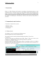
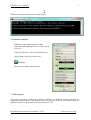
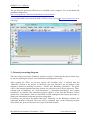
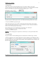
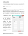
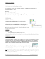
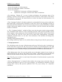
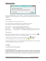
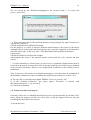
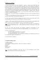
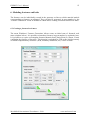
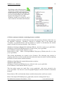
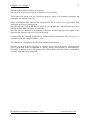
MechaRock International Consultants
User’s Manual
www.mecharock.com
October 2014
2
DISROC User’s Manual
1. Introduction
Disroc is a Finite Element code devoted to the analysis of geotechnical projects in rock
formations. Disroc is specially conceived to easily handle fractures and bolts present in the
project. In presence of these elements, the creation of a specific mesh including theme
requires using a special module called DISCRAC (DIScretization of CRACked media). In the
following, first the method for using Disroc without fractures and bolts is presented, and then
the method for including these “discontinuity” elements in the model by using Discrac is
presented.
2. Command and control interfaces
Commands are launched from 3 points:
• Windows Consol
• Windisroc interface
• GID program
2.1 Windows Consol
The Windows Consol is created from the Windows menu:
Start\All Programs\Accessories\Command Invited
The windows console created is positioned initially on the folder C:\Users\User>
C:\Users\User>
Then this consol must be positioned on the folder “Disroc”. This can be down by the
command “cd” (change directory) in the following waytype the command:
C:\Users\User>cd (PATH…\Disroc)
Instead of typing the complete path to Disroc folder, it is possible to fetch it on a windows
positioned on the folder Disroc and gliding it on the Consol window after the command “cd”
and then press ‘return’ (figure below).
MechaRock International Consultants - 2014
www.mecharock.com
3
DISROC User’s Manual
Windows consol positioned on the folder Disroc:
2.2 Windisroc interface
Windisroc is the main interface for data
acquisition and handling Disroc. It can be run in
two ways:
-from the Windows Consol run Windisroc.exe
-in the Disroc folder clic on the icon:
Windisroc
Then the following window appears.
2.3 GID interface
The project geometry, mesh and boundary conditions are defined and the materials are
assigned to different parts of the domain by the pre-processor GID. The calculation results are
displayed, plotted or processed by the post-processor GID.
MechaRock International Consultants - 2014
www.mecharock.com
4
DISROC User’s Manual
The pre and post processor GID has to be installed on the computer. For its download and
installation method see:
http://www.gidhome.com/download/official-versions/win64
It is recommended to download the GID 10.0.08 version, (see in All Other Released Versions) in
GID page.
3. General processing diagram
The order of the icons on the Windisroc window (section 2.2) indicates the path to follow step
by step for defining the project, run calculations and display the results.
After opening the “Files” for the new project, the “Problem Type” is defined, then the
“Materials” present in the project. In the basic case (non fractures), the left branch of the
diagram is followed: defining “Geometry”, “Mesh” and “Boundary Conditions”. The green
color of the buttons indicates that these actions are achieved in the GID pre-processor. Then,
coming back to Windisroc, the “Load Parameters”, “Calculation Parameters” and “Output
Parameters” are defined. The calculation program “Disroc” is run from the Windows Consol
(black color of the button). Then we return back to GID, calling this time its post-processor, to
display the calculation results and post-processing them.
If fractures are present in the model, then after “Materials” in the Windisroc window, the
right-hand branch is followed. This case will be explained later. In the following sections
more details are given for the successive steps of the basic branch.
MechaRock International Consultants - 2014
www.mecharock.com
5
DISROC User’s Manual
3.1 Project Files
All the files relatives to a project named “project” are put in a folder “project.gid”.
To start a new project, the user defines the name of the project, and the path from the folder
Disroc to the folder project.gid (in the following example, project = “test”):
In Windisroc, click on “Files”:
The following window appears:
Files
The path “projects” and the project name “test” define the following folder to be created:
C:\Users\User\DISROC\projects\test.gid\
All the files of the project “test” will be created and stored in this folder. This operation
creates the folder and automatically a set of root files like “test.cnd” which are needed for
GID or for the following steps of processing.
If an existing project is to be uploaded, do not check the case “New Project”.
The list of existing projects can be consulted in the folder
C:\Users\User\DISROC\projects\
Warning! If an existing project is opened as an “New Project”, all its specific data will be
lost.
3.2 Problem Type
The general features of the modeling project are defined in the “Problem Type” window.
• If the axi-symmetry case is chosen, then the axis of the symmetry can be different of the yaxis of coordinates (x=0). It can be shifted to a position with an abscissa x which has to be
specified. In this case, only one-half of the geometry (at the right hand of the symmetry axis)
has to be introduced in the model.
MechaRock International Consultants - 2014
www.mecharock.com
6
DISROC User’s Manual
• Plane stress (strain) conditions correspond to a zero value of the stress (strain) in
perpendicular direction of the calculation plane. Generalized plane stress (strain) conditions
correspond to a constant value of this stress (strain), which can be different from zero. This
value is specified in this window (Generalized Strain/Stress).
Warning! In the present version of Disroc, no zero values are possible only for the
Generalized Plane Stress conditions.
3.3 Materials
All the materials present in the project must be defined in advance in WinDISROC/Materials
menu. For their definition refer to the “Materials Catalogue” of Disroc.
When an new project is created, some basic material models are present in the root files. The
list of materials models available for the project can be completed in this window by adding
new materials or deleting existing ones. The materials are given a name like “Rock1” which
then can be recognized by GID to be affected to different mesh elements, surfaces or lines
(fractures and bolts).
• The material name must be a
single word (no spaces).
• The material model (a 5 digit
code), the number of parameters
and their significations are
described in the document
“Materials Catalogue” of Disroc.
• The models defined for the
mechanical
and
hydraulic
calculations must correspond to the
same type of elements (bulk
material, fractures or bolts).
• To the list of materials created
for GID will added automatically
three material names which are
“Boundary” and “Geomline” to
characterize the boundary lines and
geometrical lines for the needs of
meshing process.
• After all the new materials are
defined, it is necessary to finish by
“Save to file”.
MechaRock International Consultants - 2014
www.mecharock.com
7
DISROC User’s Manual
3.4 Geometry, mesh and boundary conditions
The « geometry », “mesh” and “boundary conditions” are defined and the materials are
affected to elements in GID.
Run GID
Menu : File/open/project.gid
Menu : /Data/ Materials
Check that materials defined in Windisroc appear well here.
Two additional materials, “Boundary” and “Geomline” will be present in the list.
3.4.1 Geometry
GID Menu : Geometry
• Define the lines: Menu/Geometry/Create/Straight line,
or use, on the tools bar the icon
• When all the lines are defined, define closed surfaces by :
Menu/Geometry/Create/NURBS Surface, or by using the icon
• Affect the materials to surfaces by: Menu/Data/Materials/Assign
and then selecting surfaces.
3.4.2 Mesh
GID Menu : Mesh
• Create Mesh by Menu/Mesh/Generate Mesh
• Check that all materials have been assigned to mesh elements (Menu: Data/Materials/Draw
all materials”)
3.4.3 Boundary Conditions
Two types of boundary conditions are considered: those defined on points and those defined
on boundary lines. The first type includes displacements, punctual forces and, if hydraulic
calculation, the fluid pressure. The second on, the normal and shear stresses applied on the
boundary and, for hydraulic calculations, the normal fluid velocity.
• GID Menu : Data/Conditions
and select the type of the condition:
• Select the boundary condition, its value, and assign it to all corresponding elements (points
or boundary lines).
Note: The boundary conditions on lines can be defined on the “Geometry” of the model, and
then will be automatically transmitted to the mesh. For the boundary conditions on point, it is
better to assign them on the mesh.
MechaRock International Consultants - 2014
www.mecharock.com
8
DISROC User’s Manual
Warning! At least three degree of freedom of displacement must be fixed to remove the rigid
body movement. Thus can be done for instance by prescribing ux = 0, uy = 0 for one point and
uy=0 for and other. If the rigid body displacement is not fixed in the way, errors will be
generated during calculation because the displacement field will be undetermined.
3.4.4 Saving Files
• Save the project with all the information on data and boundary conditions:
GID Menu File/Save
• Prepare the entry file for calculation with the format needed by Disroc. This file is called
project (without any extension) and is saved in the folder project.gid by the following
operation:
GID Menu : File/export/using Template.bas/others/ (and browse to upload DISROC_2.bas in
the Folder in the project.gid folder), browse and save in the project.gid folder under the name
project.
Note: The template file DISROC_2.bas can be copied in the folder:
C:\Program Files (x86)\GID\GID 10.0.08\templates\
and then it will be available in the list:
GID Menu : File/export/using Template.bas (list)
The entry file project created in this way is used by Disroc for calculations.
3.5 Loading Parameters
The loads prescribed on the system are partially the forces and displacements prescribed on
the boundary. This part has already been introduced in the preceding sections and is saved in
the entry file project. Other loads supported by the system may be volume forces and initial
stresses. Initial stresses my be naturally present in the rock formation when, for instance,
digging a tunnel, or may result from a preceding phases of loading of the system. After each
calculation phase, all the needed results for pursuing the loading in a next phase are saved in
the file project.rep (.rep for reprise in a next phase).
The button Load parameters gives access to the loads window.
MechaRock International Consultants - 2014
Load Parameters
www.mecharock.com
9
DISROC User’s Manual
• The window below shows
the options for a basic initial
project. There is “Non”
reprise, non volume forces
nor other special loads, and
all the loads defined in the
project (forces applied on
the boundary as “boundary
conditions”)
are
fully
applied to the system
(ratio=1). For other special
cases (excavation…), refer
to the section “Special
loads”.
“Homogenization” is not
checked. It corresponds to
special calculations that will
be explained later.
3.6 Calculation parameters
The number of load increments and the tolerance for the convergence of non linear
calculation (plasticity, non linear elasticity) as well as the resolution method (Direct or
Conjugate Gradient) are defined in the window “Calculation Parameters”. The following
window gives the default state of the options in this window.
• If only linear elastic materials are present in the model, then the loads increment will be one.
• If the message “Non convergence” for plastic or non linear elastic calculations is generated
by the calculation code, after checking that the load is mechanical bearable by the system
(specially for plasticity) and that problem is only numerical, three actions can help obtaining
convergence of calculations:
MechaRock International Consultants - 2014
www.mecharock.com
10
DISROC User’s Manual
- increase the number of load increments
- increase the Maximum number of iterations
- increase the tolerance :
Epsilon for Convergence of Plastic calculations
or
Epsilon for Convergence of Non Linear Elastic calculations
• By checking “Display f0”, in case of plastic calculations, the maximum value of the
plasticity criterion on the elements is displayed on the monitor at each iteration. This allows
controlling the convergence (f0 must decrease to values less than the fixed tolerance), but
slows down the calculation.
• The “Conjugate Gradient” calculation method is recommended for heavy projects with more
than 2000 nodes, and non linear calculation. It take more time at the beginning, but then is
faster than the Direct Method. Also it needs less storage memory volume and allows to handle
models with greater number of nodes. It needs to define a specific tolerance and maximum
number of iterations.
• The “Conjugate Gradient” method in Disroc uses also the sparse matrix storage method.
The constitution of this matrix is a time consuming operation. This operation partially consists
in the analysis of the connectivity of the elements in the mesh and the result is saved in the
project_IAJAm file. This file is the same for the same mesh, independently of boundary
conditions, materials and so on. So, after a first calculation, if the mesh has not changed, by
checking the case :
“Reading existing Storage Matrix”
the existing connectivity matrix is red, and this allows saving time specially for great projects.
3.7 Output parameters
The calculation results, the state of displacement and stress field at the end of calculation, so
for the total load, are put in the file project.post.res which is read and displayed by the GID
post-processor (see following sections). If an incremental calculation is carried out, it will be
interesting to see the evolution of displacement and stresses for different load increments.
• The displacement values for one node and the stress and plastic strains for one element at
different load levels are put in a file called project.courbe. The number of the selected node
and the selected element for this purpose are defined in the window “Output parameters”.
Note: The file project.courbe is created only if the number of load increments is greater than
one (see Load Parameters).
• If the “Homogenization” is checked in this window, the average stress and strain values at
each load increment are put in a file project.epsigmoy for mechanical calculation, and the
average fluid velocity and pressure gradient in the file project.vitmoy for a hydraulic
calculation.
MechaRock International Consultants - 2014
www.mecharock.com
11
DISROC User’s Manual
Note: If “Homogenization” in this window is checked the homogenized quantities are
calculated even if the calculation does not correspond to a Homogenization loading (see the
section 5.3)
3.8 Calculation
• From the Windows Consol launch “Disroc project”
If the calculation ends successfully the message “DISROC End” appears.
The results are presented in several files in the folder project.gid:
project.post.res
that is used for post processing by GID
project.courbe created for incremental calculations (see section 3.7)
project.rep
that contains the needed results for a possible “reprise” (see section 3.5)
project.epsigmoy
or project.vitmoy
that contain homogenization results (see section
3.7)
3.9 Post-process
Retrun back to GID (where the file project is loaded). Click on post-processing button
The post-process file project.post.res is automatically uploaded.
To display the desired results, on the tools bar click on the button
.
.
To create graphs and cuts, on the tools bar click on the button
The figures and graphs can be save in files (GID Meny/Files/Print to file) to be used as figures
or read (for graphs) by other softwares like Excel.
4. Staging
4.1. Tunnel excavation without support
To model tunnel excavation:
1) First the initial state of the formation before excavation is modeled by a whole mesh
(containing the elements corresponding to the tunnel section) on which are applied suitable
boundary conditions and volume forces to create initial in situ stresses. After calculation of
this state, the project file and the calculation results which are put automatically in project.rep
MechaRock International Consultants - 2014
www.mecharock.com
12
DISROC User’s Manual
file, are copied by the (Windisroc/Staging/Save the present results…) in project_init
project_int.rep files
- 2) Then, returning back to GID, the mesh elements corresponding to the tunnel section to be
excavated are removed:
GID Menu/Mesh/Edit mesh/Delete/Elements
For this purpose, it is easier to assign a different material name to the section of the tunnel,
although with the same model and properties than the rest of the formation, to facilitate their
selection at this stage. In this case, after GID Menu/Mesh/Edit mesh/Delete/Elements
On can press:
GID Menu/Utilities/Tools/Selection window
and designate the name of the material (tunnel section) that has to be selected and then
remove.
- 3) All the boundary or volume forces as well as non zero boundary displacements must be
removed in the project, because their effect is already included in the initial stresses obtained
in the previous calculation. However zero displacement conditions on the boundary can be
maintained.
Note: In any case, at least three zero displacement degrees of freedom must be maintained in
the boundary conditions in order to eliminate the rigid body movement (see section 3.4.3)
4) The entry file is created by the template DISROC-2.bas (see section 3.4.4)
5) In the “Loading Parameters” the reprise option “Ecavation” is selected, with
Maximum load ration = 1 (see section 5).
6) Launch the calculation.
4.2. Tunnel excavation with support
Generally in this case it is admitted the initial stresses are released partially (for instance 70%)
before laying the support, and the rest (30%) after, so that the support will bear only this
remaining part the initial in situ stresses.
To model this case :
MechaRock International Consultants - 2014
www.mecharock.com
13
DISROC User’s Manual
1) First, the full mesh for the rock formation + support + tunnel section filled with rock
(before excavation) is created. The material properties of the rock formation are assigned to
the tunnel section to be excavated and also to the support, in order to obtain the natural state
of the formation before excavation, but in which the mesh elements for the future tunnel
section and support are already present (with rock formation properties). The initial state of in
situ stresses is created by applying suitable loads (boundary or volume forces). Then the
operations are completed as in the stages 1) to 6) for the tunnel without support described in
section 4.1 with these differences:
- in the stage 2), the mesh elements corresponding to the tunnel section and support must be
deleted.
- in stage 5), to the Maximum load ratio must be given the value corresponding to the ratio of
stresses released before excavation (for instance 0.7)
2) Then, again with the Windisroc/Staging the results are saved as the initial state for the
following stage. The new project_init and project_init.rep are created.
3) Back in GID, starting with the initial full mesh, only the elements corresponding to the
tunnel section are removed, keeping the elements corresponding to the support.
Note: The full mesh can be saved by : GID Menu/Files/Export/GiD mesh, and uploaded by
GID Menu/Files/Import/GiD mesh. When importing a mesh it is necessary to erase the
existing mesh.
4) The new mesh with necessary the boundary conditions corresponding to zero
displacements (to be checked) is saved by the template DISROC_2.bas (see section 3.4.4)
5) In the “Load Parameters”,
- the reprise option “Initial Stresses” is selected.
- the “Ecavation Boundary Forces” is checked
- the Maximum load ratio is put equal to the remaining part of initial in situ stresses to
be realsed on the support (for instance 0.3)
6) The calculation is launched
5. Special loading cases
5.1 Reprise options
In the window “Loading Parameters”, there are 4 options for “Rerprise”
Non reprise
Reprise
Initial stresses
Excavation
Non: Non reprise corresponds to the basic case of a first calculation: all the fields,
displacements and stresses, start with zero initial values
MechaRock International Consultants - 2014
www.mecharock.com
14
DISROC User’s Manual
Reprise: The displacements, stresses and other internal variables (plastic strain) start with the
values given in the project.rep file representing the values reached at the end of a preceding
phase of calculation. The project.rep file is created automatically after each calculation.
Initial Stresses: Only the stresses are given initial values. The initial stress values are read in
the file project_init.rep. This file is created after a previous calculation, by the command
“Staging” in Windisroc.
Excavation: The initial stresses are read in the file project_init.rep and the mesh is compared
to that saved in the project_init.rep after a previous calculation by the command “Staging” in
Windisroc. The boundary between the two meshes is determined. If for instance a tunnel
excavation is considered, this boundary corresponds to the tunnel wall.
At the boundary of the two meshes, surface tractions equal to the opposite value of the initial
stresses are applied as loads in the actual project to compensate the initial stress and lead to a
final state of stress-free boundary.
5.2 Excavation Boundary Forces
These forces are equal to the action of the in situ stresses on the wall of a tunnel before
excavation. They are automatically calculated if the option “Excavation” is selected in the
Loading Parameters window. They can also be calculated by comparison between the project
and project_init files with the stresses in project_init.rep, by the command Windisroc/Staging/
Extract boundary forces….
In both cases, they are put in a file project__ExcavBC.
5.3 Homogenization loading
This special option allows applying special boundary displacement or boundary forces
conditions to calculate the effective elastic moduli of a heterogeneous domain. If this option is
selected, not boundary conditions nor forces are needed nor admitted by the program which
itself manages all is required. Only the load direction. For more explanation see the Disroc
Diaporama.pps (to be downloaded from www.mecharock.com).
MechaRock International Consultants - 2014
www.mecharock.com
15
DISROC User’s Manual
6. Modeling fractures and bolts
The fractures can be individually created in the geometry as lines to which material models
corresponding to fractures are assigned. They can also be generated, in great number, by the
“Fracture Generation” menu in Windisroc which allows creating a model fractured rock mass.
6.1 Creating a fractured rock mass
The menu Windisroc/ Fracture Generation/ allows create an initial state of fractured rock
mass (window below). It is possible to introduce fractures in great number by stochastic laws.
It is possible to to create a rectangular fractured domain from (Xmin,Ymin) to (Xmax, Ymax)
containing the families of fractures. This domain is uploaded by GID as the initial geometry
on which complementary elements (mesh, boundary conditions, etc.) will be created.
MechaRock International Consultants - 2014
www.mecharock.com
16
DISROC User’s Manual
By clicking on the following icons
information messages about the processing
method appear (like in the right window
below). By following these messages, the
process correseponding to the right-hand
branch of the diagram in the main
Windisroc window (see section 2.2 and 3)
can be achieved for models with fractures.
6.2 Mesh creation for domains containing fractures and bolts
After assigning “materials” to all the lines present in the geometry (fractures, bolts, bars, see
the Materials Catalogue), “Boundary” material to boundary lines of the domain and
“Geomline” to geometrical lines used for instance to separate to sub-domains, the domain
must be divided in closed sub-domains. This is done by:
GID Menu: Files/Import/Batch file/LineMesh_GID.bch (this file is in the project.gid folder)
GID Menu: Files/Export/GID Mesh/project_F.msh in the project.gid folder
From Windows Consol, launch: Discrac 1 project
Return back to GID, Menu: Files/Import/Batch File/project_GID.bch (this file is in the
project.gid folder)
Then closed sub-domains are created in the Geometry. The following step consists in
assigning materials to surfaces (bulk materials) and mesh (only) the surfaces and then splitting
the nodes to create fracture and bolt elements:
GID Menu: Data/Materials assign bulk materials to surfaces
GID Menu: Mesh surfaces
GID Menu: Files/Export/GID Mesh/project_M.msh in the project.gid folder
From Windows Consol launch: Discrac 2 project
This last action creates two mesh files: project_graph.msh and project_cal.msh in the
project.gid folder. The first one is used for graphical purposes and the second for calculation
purposes.
Return back to GID, and check that fracture and bolt elements have well been created:
Menu: Files/Import/GID Mesh/project_graph.msh (erase the existing mesh if any )
MechaRock International Consultants - 2014
www.mecharock.com
17
DISROC User’s Manual
GID Menu/Data/Materials/Draw all materials
The fractures are bolts must appear as distinct lines in the mesh.
Then, upload the mesh used for calculation purposes, apply to it boundary consitions and
created the calculatione entry file:
Menu: Files/Import/GID Mesh/project_cal.msh (this file is in the project.gid folder) with
erasing the previously existing mesh
The discontinuities exist in this file but can not be seen graphically. If the materials are drawn:
GID Menu/Data/Materials/Draw all materials
Then the name of materials corresponding to fractures and bolts appear in the legend of the
figure but the fractures can not be seen on the mesh.
On this mesh, the boundary conditions are defined and the calculations entry file project is
created by using the template DISROC_2.bas
The calculation is launched as for the cases without discontinuities.
Warning: At the post-processing stage, if fractures are present in the model, again the mesh
project_graph.msh must be imported to display results corresponding to discontinuities.
Elsewhere, a message error is first generated by GID, and then only the results corresponding
to surface elements can be displayed.
MechaRock International Consultants - 2014
www.mecharock.com