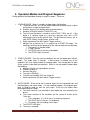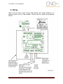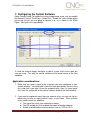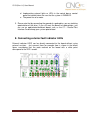
1
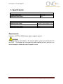
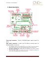
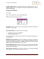
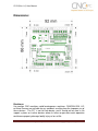
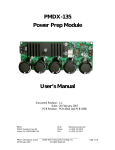
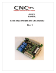
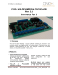
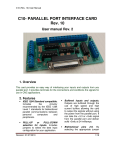
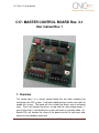
C17 (Rev.3.1) User Manual
C17- MASTER CONTROL BOARD Rev. 3.1
User manual Rev. 1
1. Overview
This board works as a master control board that will allow enabling and
monitoring your CNC system. It will allow implementing a master start switch to
enable the system. The board will then enable the drivers and an on-board
relay. Then it will monitor the drivers, e-stop, and the safety charge pump. If
any of these faults, it will disable the system and return to stand-by mode. OnBoard LEDs will indicate the status of the board and will let you know what
where the fault condition came from.
Revision: 31/03/2009
http://cnc4pc.com/TechDocs/C17R3_1_User_Manual.pdf
1/21
C17 (Rev.3.1) User Manual
The board is implemented based on an ATMEL Microcontroller. That allows
the implementation of complex algorithms. The firmware could be upgraded by
replacing the chip that is mounted on a socket.
The board can also be configured using the on-board DIP switch. At this time
you can enable and disable the safety charge pump, and select the program for
the driver you are using.
2. Features
•
•
•
Monitors E-Stop, Safety Charge
Pump, and Drivers (it only
monitors (G320/340 drives at
this time)
Microcontroller Based System.
The microcontroller based system
allows the implementation of
complex algorithms for monitoring
the system. It also allows the
possibility of having firmware
upgrades without having to
change the board and rewire your
system.
On-Board Relay for controlling
external devices.
The board comes with an onboard relay that allows you to
enable a breakout board, a
contactor, a motor, or any other
device. Multiple relays could be
connected externally in parallel if
you need to control different
signals and currents.
For
example, you might need to use
the external signal to enable a
breakout board, then you need
another signal to enable a
contactor, and then another relay
Revision: 31/03/2009
to interrupt the line that powers a
motor.
•
Status LEDs on all inputs and
output connections.
No more guessing. You can SEE
all your signals. Save valuable
time and brainpower for CNCing.
•
All TTL +5VDC or +3.3VDC
Signals.
Interface directly with parallel port
interface products and other
cnc4pc.com cards. 5VDC (TTL)
signals are very common among
automation devices.
•
Screw-On connections for all
terminals.
You only have to screw-on the
wires
to
make
all
your
connections.
•
Flexible design.
It works with cnc4pc’s products,
directly through your parallel port,
or through many other parallel
port control products.
http://cnc4pc.com/TechDocs/C17R3_1_User_Manual.pdf
2/21
C11G (Rev. 8.1) User Manual
3. Specifications.
DIGITAL INPUT SPECIFICATIONS
On-state voltage range
Maximum off-state voltaje
2 to 5V DC
0.8V
DIGITAL OUTPUT SPECIFICATIONS
Maximum output voltage
(5V power supply voltage) + 0.5V
Typical output current
24mA
Maximum off-state voltaje
0.44 V
Requirements:
It requires a 5VDC @ 400 milliamps power supply to operate.
WARNING
Check the polarity and voltage of the external power source and connect the 5V
and GND. Overvoltage or reverse-polarity power applied to these terminals can
cause damage to the board, and/or the power source.
Revision: 31/03/2009
http://cnc4pc.com/TechDocs/C17R3_1_User_Manual.pdf
3/11
C11G (Rev. 8.1) User Manual
4. Board description
Power input connectors:
board.
Provide a 5V@400mA power supply to power the
Input signals connectors: In order to take the board to activate mode, the
following conditions must be met:
1. THE TERMINALS MUST BE ACTIVATED WITH A HI OR +5VDC. The pin to the right has
+5vdc and the input pin is to the left. A NC (Normally Closed) switch should be used.
2. THE SAFETY CHARGE PUMP SIGNAL MUST BE PRESENT (If this feature is enabled
with the DIP switch selector).
3. THE START SWITCH MUST BE CLOSED FOR AT LEAST 5 SECONDS TO START THE
CYCLE. NOTE: NO (Normally Open) switch must be used
Revision: 31/03/2009
http://cnc4pc.com/TechDocs/C17R3_1_User_Manual.pdf
4/11
C11G (Rev. 8.1) User Manual
Standby indicator LED: The standby led will light to indicate that the system is
ready but disabled. If the system faults it will lite again to indicate that the system is
ready to enabled again.
Configuration DIPSWITCH:
DIP 1: Spare
DIP2: Turns on and off the safety charge pump feature.
DIP3 and 4: Selects the driver you will use.
Fault LEDs: When the system stops, the fault indicators will light to indicate what
caused the system to stop.
Status LED indicator: The status LED has three modes:
1. Off when the system is off or in standby mode.
2. Blinking, when the system is coming up.
3. On when the system is active.
The external terminal is the user can install an LED in outside the control box or in
the control panel.
ERR/RES Drivers Connectors: The driver enable or err/res terminals of the driver
must be connected to this terminals. the pin will behave according the driver to
which it was selected to operate with. if a g320 is selected, the system will not only
enable the drive, but it will monitor it to see if it faults.
External trigger connectors: When the system faults an external activation signal
is sent for 3 second. This is so you can let the controller know that the system has
faulted and it is coming down.
Relay contacts connectors: The relay is so you can use it to enable and disable
external devices. Such as motors, contactors, VFDs, etc...
Revision: 31/03/2009
http://cnc4pc.com/TechDocs/C17R3_1_User_Manual.pdf
5/11
C11G (Rev. 8.1) User Manual
5. Operation Modes and Program Sequence:
During operation the board goes through 3 stages or modes. These are:
1. STAND-BY MODE. When in stand by the board does the following:
a. The driver terminals are set into output mode and the board sends a signal
to the drivers in order to disable them.
b. Disables the relay (this disables other external devices).
c. Stand-by LED lights and the STAUS LED is off.
d. The first time the board is turned on all the FAULT LEDs are off. If the
board is in stand-by mode as a result of a previous fault, then a LED
indicating the cause of the fault will light. The possible fault causes are: estop, SCHP (Safety Charge Pump), or driver fault.
e. Sends a ground or 0 to the External Trigger terminal.
f. Monitors the system to see if it is ready to go to START-UP mode. The
conditions to be met for the board go to into start up mode are the following:
i. The board is in Standby mode.
ii. E-stop is closed.
iii. The SCHP signal is present (or disabled).
iv. The START signal is present.
2. START-UP MODE. Once the start-up conditions are met, the board goes into this
mode. This mode takes 5 seconds. If during these 5 seconds any of the
conditions fails, then it goes to back to stand-by mode. This time period is to allow
all the systems to be ready for operation. When in start up mode the board does
the following:
a. Monitors that the start up conditions are met.
b. Enables the drivers.
c. Activates the relay
d. The status LED blinks.
e. The fault and stand by LEDs are turned off.
f. Sends a ground or 0 to the External Trigger terminal.
3. ACTIVE MODE. At the end of the 5 seconds when the start up period ends and
the board goes into active mode. If a fault condition appears, the program goes
back to stand-by mode to start the cycle again. These are the actions been
performed during this mode:
a. The driver terminals are switched to input mode and start monitoring the
drivers.
b. The system monitors all the conditions for the system to remain active.
These are:
i. The e-stop open. It is left in the air, or receiving a ground.
ii. The SCHP signal is present. (if configured).
iii. The drivers are not sending a fault signal.
c. The STAUTS LED lights.
d. The relay is activated.
Revision: 31/03/2009
http://cnc4pc.com/TechDocs/C17R3_1_User_Manual.pdf
6/11
C11G (Rev. 8.1) User Manual
e. Sends a ground or 0 to the External Trigger terminal. But if the system
faults, a hi or +5vdc signal is sent for 3 seconds. This is so you can let the
controller know that the system is coming down. This signal can be
connected to the controller’s e-stop or limit input.
f. The system halts for 3 seconds. After these 3 seconds the system could be
reactivated.
Revision: 31/03/2009
http://cnc4pc.com/TechDocs/C17R3_1_User_Manual.pdf
7/11
C11G (Rev. 8.1) User Manual
6. Wiring
Make sure you send a signal to the e-stop input pin your control software, so it
becomes aware of the e-stop condition. Please note the sample wiring diagram
bellow.
Revision: 31/03/2009
http://cnc4pc.com/TechDocs/C17R3_1_User_Manual.pdf
8/11
C11G (Rev. 8.1) User Manual
7. Configuring the Control Software
Safety Charge Pump: To enable the safety charge pump, make sure you enable
the feature in Config / Pins&Ports / Output Pins. Enable the safety charge pump
and assign the pin you are going to connect it to, as is shown in the follow
Figure. Next, press the apply button.
If using the external trigger, configure e-stop or assign a limit to the input pin
you are using. This way the control software will be made aware of the fault
condition.
Application considerations:
1. Make sure you send a signal to the e-stop pin you have configured in your
control software. You could take it from the same push-button you are using
for e-stop, but if you take it from the on-board relay, then if a servo motor
fails, then the system will let the control software know of the fault condition.
2. If you need to implement more than one external relay, you can use the onboard relay to drive as many external relays as you need. These external
relays could control the following:
a. The signal that starts your contactor or motors.
b. The EN (enable pin) that enabled the output of breakout boards.
c. Enable or disable other external devices such as VFDs or PLCs.
Revision: 31/03/2009
http://cnc4pc.com/TechDocs/C17R3_1_User_Manual.pdf
9/11
C11G (Rev. 8.1) User Manual
d. Implementing external lights or LEDs in the control box or control
panel that would inform the user that the system is ENABLED.
e. The power line of a motor.
3. Please note that by connecting the ground of a geckodrive, you are violating
optoisolation of the drive. If you still want the benefit of optoisolation, you
can use an optoisolated breakout board, such as the C1 – Parallel Port
Interface Card to keep your system optoisolated.
8. Connecting external fault indicator LEDs
External indicator LEDS can be directly connected to the board without using
external resistors. Just connect them for example how is shown in the follow
figure, considering that the pads marked on the board with a white point
correspond to the LED’s anode.
Revision: 31/03/2009
http://cnc4pc.com/TechDocs/C17R3_1_User_Manual.pdf
10/11
C11G (Rev. 8.1) User Manual
Dimensions:
Disclaimer:
Use caution. CNC machines could be dangerous machines. DUNCAN USA, LLC
or Arturo Duncan are not liable for any accidents resulting from the improper use of
these devices. The C17 is not fail-safe device, and it should not be used in life
support systems or in other devices where its failure or possible erratic operation
could cause property damage, bodily injury or loss of life.
Revision: 31/03/2009
http://cnc4pc.com/TechDocs/C17R3_1_User_Manual.pdf
11/11