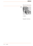
1
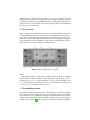
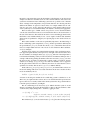
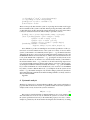
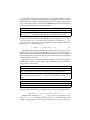
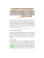
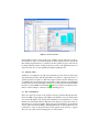
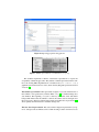
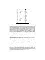
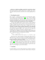
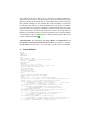
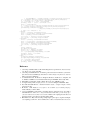
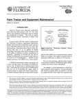
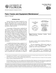
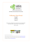
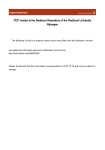
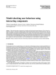
Systematic analysis of control panel interfaces using
formal tools?
J. Creissac Campos1 and M. D. Harrison2
1
Department of Informatics/CCTC, Universidade do Minho, Braga, Portugal
[email protected]
2
School of Computing Science, Newcastle University, UK
[email protected]
Abstract The paper explores the role that formal modelling may play in aiding
the visualisation and implementation of usability requirements of a control panel.
We propose that this form of analysis should become a systematic and routine
aspect of the development of such interfaces. We use a notation for describing
the interface that is convenient to use by software engineers and describe a set of
tools designed to make the process systematic and exhaustive.
1
Introduction
Applying formal techniques to analyse interactive systems makes possible a more systematic approach to the evaluation of the usability of a new design. Formal techniques
can provide an incisive analysis that is effective in uncovering potential unforeseen interaction problems. These potential problems, once uncovered, can be explored from
a usability perspective. The paper demonstrates how a collection of property patterns
(akin to those described in [10]) can be used to make this process more systematic.
These patterns are tool supported. The interface under analysis is specified using a
notation that focuses on the meaning and effect of action (Modal Action Logic). The
approach is illustrated by analysing the air conditioning system for a family car. In addition to potential usability problems, the patterns help discover discrepancies between
assumed meanings based on the user manual and meanings derived by experimenting
with the system. The approach is similar in aim to that of [5] and [12]. The focus here
is to make formal techniques more routine and systematic.
Techniques are required that fit naturally with the programmer’s view of the system
while at the same time triggering a usability perspective. The paper describes:
1. a notation that clearly and simply captures the characteristics of the interactive
device
2. a set of properties that can be systematically checked of the interactive system
3. a tool that can pull together the means of specification and the means of checking,
in a form that makes it accessible to appropriate developers.
?
Preprint of the paper published in Interactive Systems: Design, Specification, and Verification,
volume 5136 of Lecture Notes in Computer Science, 2008. The final publication is available
at Springer via http://dx.doi.org/10.1007/978-3-540-70569-7 6. Winner of a BCS HCI International Excellence Award 2009.
Finally a means of exploring the consequences of a discovery is required once these
techniques have uncovered a potential problem. The systematic approach is supported
by the IVY tool developed to check MAL specifications. The paper explains the characteristics of the tool and comments on how the formal approach can be complemented
by a more user focussed analysis.
2
The case study
This case study explores the design of the automatic air conditioning panel of the Toyota
Corolla (2001 European version). The actions associated with the air conditioning system concern setting temperature and altering the rate and direction of the flow of air.
While the actions associated with temperature and rate of flow are relatively straightforward, complications involve the number of modes that deal with the direction of flow.
The complete set of actions and displays is identified below.
Figure 1. The air-conditioning control panel
Figure
The displayed indicators are perceivable attributes of the state. These are identified
in the model by the names in brackets in the following list: (a) flow mode (airflow );
(b) fan speed (fanspeed ); (c) target temperature (settemp); (d) air-conditioning on/off
(ac); (e) wind screen (front) flow mode on/off (front); (f) recirculation air intake mode
(airintakefresh); (g) automatic mode on/off (auto).
3
The modelling notation
A specification using modal action logic is produced that focusses on actions and attributes of the state that are relevant. This set of actions and attributes may be modified as
the specification evolves. Additional assumptions about the specification may be identified by experiments with the system for example. A fuller description of the semantics
of MAL can be found in [6,1]. The specification is structured around the hierarchical
interactive components that appear in the interface (called interactors). In the present
example one interactor describes actions as well as visible attributes of the state of the
system. It is clear that in an air conditioning system it is also possible to feel or hear the
effect of changes in the temperature, fan speed and where the air is flowing, but these
additional modalities are ignored. Context effects, for example whether the car windows are open or not, are also ignored for the purposes of this analysis. These aspects
of the system may be considered informally as an adjunct to the analysis if appropriate.
There are three types of MAL axioms. Propositional axioms describe invariants
over the state of the interactor. Modal axioms describe the effect of an action in terms of
the state of the interactor. The modal axioms can be seen as describing production rules
that define a state machine. Finally deontic axioms capture conditions that determine
when actions are permitted or obligatory. For present purposes the deontic axioms are
ignored.
Three visible attributes of the state are particularly important to the functioning of
the air conditioning system: temperature (settemp), the flow speed that is defined by the
fan speed indicator (fanspeed ) and the flow mode (airflow ) that defines where the air
flows, for example dashboard level or floor level or to the windscreen. These attributes,
see (a)-(c) in Figure
Normal logical operators are assumed in this fragment of the specification and actions appear in square brackets. The expression to the right of the action describes how
the state attributes are changed. In the case of [tempup] therefore if the temperature is
lower than the maximum possible (MAXHOT ) then it is incremented. The new state of
settemp is indicated by priming the attribute, hence the new value (settemp 0 ) becomes
the previous plus one. If the set temperature is already equal to MAXHOT , then its
value does not change: (keep(settemp)). Note that if an attribute does not appear in
the keep list and its behaviour is not defined by the axioms its value after the action is
specified to be random. The axiom for tempdown is defined similarly.
In the same way [fanspeedup] and [fanspeeddown] are defined. More axioms are
involved in dealing with actions associated with where the air flows. Possible air flow
modes are defined by the set:
AirFlow = {panel , double, floor , floorws, wsclear }
A feature of the design is whether the air conditioning system is switched on or off.
This is not yet captured in these axioms. It is not an accident that this aspect has been
ignored, since it is not clearly visible in the current system. The only possible indicator
is the fan speed (see indicator (b) in Figure
The air conditioning mode selector key (5) is defined when the system is on and
when it is off. When off, pressing the button has no effect on the state attributes, when
on the mode key simply changes the ac attribute, toggling its value.
on → [ackey] ac 0 = ¬ac ∧
keep(auto, airintake, settemp, on, front, airflow , fanspeed )
¬on → [ackey] keep(auto, airintake, settemp, on, front, airflow , fanspeed , ac)
The windscreen (flow ) mode selection button [frontkey] has the following axioms:
on → [frontkey] on 0 ∧ front 0 = ¬front ∧ keep(settemp)
¬on → [frontkey] on 0 ∧ front 0 ∧ keep(settemp)
[frontkey] front 0 → (¬auto 0 ∧ ¬airintake 0 ∧ ac 0 )
front ↔ airflow = wsclear
These axioms specify that when the system is on pressing the front button will toggle
the front attribute. If the system is switched off then pressing the frontkey will switch it
on. The final axiom specifies an invariant, namely when the front mode is set the airflow
is always in windscreen clear mode. The modekey is specified as follows:
[modekey] ¬auto 0 ∧ ¬front 0 ∧ keep(airintake, settemp, on, fanspeed )
¬front → [modekey] (airflow = panel → airflow 0 = double)
∧(airflow = double → airflow 0 = floor )
∧(airflow = floor → airflow 0 = floorws)
∧(airflow = floorws → airflow 0 = panel ) ∧ keep(ac)
[airintakekey] airintake 0 = ¬airintake∧
keep(auto, settemp, on, front, airflow , fanspeed , ac)
It was difficult to produce an unambiguous and accurate specification of this system based on both the manual and use of the system for a variety of reasons. In this
system: (a) the manual is not sufficiently clear in places — e.g., the manual states that
“When the [Front] key is pressed, air flows mainly through the windscreen vents, and
the FRESH air intake mode is automatically set” which is only true when the front mode
is off; (b) the manual lacks completeness — e.g., pressing the mode key in auto mode
turns the mode indicator off and this is not described in the manual; (c) the manual is
inconsistent with the device — e.g., references to the A/C button being depressed are
not consistent with the actual user interface where buttons do not have a depressed state;
(d) descriptions within the manual are mutually inconsistent — e.g., “press the MODE
key to switch off AUTO mode” and “in AUTO mode you do not have to use the MODE
key, unless you want a different flux mode”; (e) assumptions about the system are left
unsaid — e.g., the manual descriptions only describe changes produced by the buttons
and assume that what is unmentioned remains unchanged which is as already stated not
what is assumed in MAL.
Appendix
4
Systematic analysis
The first type of analysis is concerned with the credibility of the system, exploring those
properties that should be true in terms of a plausible mental model of the system. For
example, what can only be true if the system is switched on.
AG(auto → on)
(1)
The property is described in CTL (Computational Tree Logic, see for example, [4])
and asserts that auto mode can only be armed if the system is on. In the version of
the system specification based only on the manual this property is not true, a counterexample is generated by the model checker showing that the air intake key is arming
the automatic mode without switching the system on. This counterexample indicated a
flaw in the specification. A new specification in which the previous state of the system
could be recovered even though the system had been switched off fixes the problem.
Exploration of other properties indicates that when switching between modes (for example from auto mode to front mode and back) the system keeps a memory of the state
in each mode. In the specification a variable acmem is used to define the state of the ac
mode. This and further exploration of system actions produces further changes to the
specification (see Appendix
The axioms that relate to acmem are as follows:
[ackey] acmem 0 = ac 0
[a : −{ackey}] keep(acmem)
front → [modekey] ac 0 = acmem
¬on → [a : {fanspeedup, fanspeeddown}] ac 0 = acmem
[frontkey] ¬front 0 → ac 0 = acmem
When ackey is pressed, acmem stores the new value of ac (first axiom), all other
actions do not change its value (second axiom — note use of a : −{ackey} which
defines actions a not including ackey); pressing modekey when the front mode is on,
puts the air conditioning mode in the state stored in memory (third axiom), and the same
happens when fanspeedup or fanspeeddown are pressed while the system is off (fourth
axiom), or if pressing frontkey leaves the front mode on (fifth axiom). Property
Standard patterns were developed for the systematic analysis of interactive systems
some of which are now described. Due to space constraints, only minimal information
on the patterns is provided. This include presenting the basic (no concurrency) formulations only. The patterns use a number of notational assumptions. s is the valuation of the
attributes in the current state (S), c ⊆ dom(ρ) (with ρ : Attributes → P resentation
defining the presentation modalities) a subset of perceivable attributes, =∗ is equality
distributed over attributes in the state, a an action, AXa p a shorthand for AX(a → p)
(i.e. in all next states arrived at by a, p holds), 6=∗ means at least one attribute must be
different, and pred an optional predicate used to constrain the analysis to a sub-set of
states. The patterns are formulated in a CTL like logic that is transformed into correct
CTL by the IVY tool. This tool is described in Section
Feedback is a key property of a good user interface that helps the user gain confidence in the effect of actions and create an appropriate mental model of the system.
Feedback properties can be verified with the following pattern:
Property Pattern: Feedback
Intent: To verify that a given action provides feedback.
Formulation: AG(pred (s) ∧ c =∗ x → AXa (c 6=∗ x ))
Under the defined condition (pred), the action (a) will always cause a change in some
perceivable attribute (in c).
If the mode key is instantiated in the pattern, i.e., a ≡ modekey and feedback is
provided by the airflow indicator (see indicator (a) in figure
In the case of fanspeedup with associated indicator fanspeed (see indicator (b) in
figure
Consistency of action is another characteristic of a system that facilitates predictability and learning. Consistency can be internal (between different parts of the system) or
external (with other systems). Consider internal behavioural consistency. Four buttons
act as on/off switches (the A/C, Auto, Mode and FRONT buttons) and look the same. It
should be expected that they have the same behaviour.
Property Pattern: Behavioural consistency
Intent: To verify that a given action causes consistent effect.
Formulation: AG(pred (s) ∧ s =∗ x → AXac (effect(x , s)))
with effect : 2(S×S) characterising the effect the action should have in the state.
This generalization of the Feedback pattern states that the action must always cause
the same effect in the user interface. The candidates for test are buttons ackey, frontkey,
airintakekey and autokey, the relevant state is the status of each button (ac, front,
airintake and auto, respectively), and the desired effect is the toggling of that status.
In the case of ackey, the pattern gives:
AG(ac = x → AX[ackey]ac = ¬x)
(2)
All the instantiated properties hold when the system is switched on except [autokey].
In the case of [autokey] the button only turns the mode on, it does not turn it off. One of
the interesting features of this design is that when the system is off there are a number of
unexpected side effects originated by pressing some of these buttons (namely, changes
to their subsequent behaviour).
Although one form of undo has been analysed already (for the on/off switches),
another pattern relevant to systems such as this is whether there are actions that can
undo the effect of other actions.
Property Pattern: Undo
Intent: To check whether the effect of an action can be undone.
Formulation (any action): AG(s =∗ x → AXa1 EX (s =∗ x ))
with a1 the action whose effect we want to undo, any action required to undo.
Formulation (specific action): AG(s =∗ x → AXa1 (EX (a2 ) ∧ AXa2 (s =∗ x )))
with a2 the action that should undo a1 , and the action availability test (EX (a2 )) optional.
Property Pattern: Reversibility
Intent: To check whether the effect of an action can be eventually reversed/undone.
Formulation: AG(s =∗ x → AXa1 EF (s =∗ x ))
In the case of the mode button this pattern checks whether there is another action
that can be directly identified as performing its undo. Focussing on the airflow indicator:
AG(airflow = x → AXmodekey AXxaction (airflow = x ))
(3)
Attempting the verification for xaction = autokey fails for all properties, except
when airflow = floorws. This leads to an exploration of (a) why it fails and (b) why
it holds for the particular case. The property fails because modekey does not have a
Figure 2. IVY Architecture
symmetric action that undoes its effect (on the airflow mode). Exploring an answer
to the second question leads to the unexpected conclusion that the modekey action is
unavailable when the air flow mode is floorws. The mode key action should always
be available to allow the flow mode to be changed. The model has been specified so
that the user can always press the buttons but this does not imply that pressing a button
always has an effect. The problem is that the cyclic behaviour ‘implemented’ by the
mode button includes wsclear but this mode should only be accessible by using the
front key. The separate question as to whether the modekey can always be undone by
some means leads to a positive answer.
AG(airflow = x → AXmodekey EF (airflow = x ))
5
(4)
Checking patterns using IVY
The IVY tool supports the patterns described in the previous section and has an architecture given in Figure ??. The tool has four main components: a model editor designed
to support the development of MAL interactor models; a property editor designed to
support the expression of relevant usability related properties as logical formulae; a
translator (i2smv) that transforms interactor models into the model checker’s input
language; a trace visualizer/analyser helps the analysis of any traces produced by the
model checker.
5.1
The model editor
The editor supports the structure and syntax of MAL [1] interactors in two editing
modes indicated in the two windows of figure ??. In the first mode (graphical mode)
the overall structure of the model can be viewed and manipulated while at the same
time providing an individual edit capability. The second mode is textual (with the usual
editing facilities: cut and paste, undo and redo for example). This mode supports direct
editing and fine tuning. The interactor in graphical mode is based on UML class diagrams [11]. Interactor aggregation and specialisation uses an approach consistent with
UML. The intention is to make it easier for designers to understand a model’s representation. In graphical mode a number of inspectors are provided to make it possible to
Figure 3. IVY Model Editor
edit the different aspects of the model (types, attributes, actions and axioms of the selected interactor, and so on). Textual mode allows direct editing of the text of the model
thus enabling experienced users to edit the model more quickly. Aspects of the text can
be changed directly instead of using the inspector panels of the graphical mode. Less
expert users may choose more guidance through the graphical mode.
5.2
Property editor
Verification of assumptions about the expected behaviour of the device is achieved by
expressing CTL properties. The Property Editor uses patterns to support the choice of
specific properties (see figure ??). The editor supports pattern selection, making it easy
to instantiate the chosen pattern expressed in CTL (or LTL) with actions and attributes
from the model as shown in the figure. Verification is achieved from the translated MAL
interactors by the NuSMV model checker [3]. The trace visualizer can then be used to
analyse counter-examples or witnesses after the checking process.
5.3
Trace visualisation
Traces are expressed in terms of the variables and states generated through the translation into SMV’s input language. The SMV model includes some state artefacts that
were created through this step. An important element in trace visualisation is to ensure
that the states and variables that are displayed for the analyst are only in terms of the original interactors. A typical example of this reversion is the elimination of the attribute
‘action’, annotations used in SMV to distinguish MAL actions. The visualization component aims to focus on the problem that is being pointed out by the trace to support
discovery of possible solutions reducing the cost of the analysis.
Figure 4. Expressing properties using patterns
Figure 5. Tabular representation: no feedback for fanspeedup
The visualiser implements a number of alternative representations to explore the
acceptability of different approaches. They include: a tabular representation that is similar to the existing SMV implementation of Cadence Labs (www.cadence.com); a
graphical representation based on states; and an Activity Diagram representation based
on actions [7].
The tabular representation This representation (figure ??) presents information in a
table similar to that generated by Cadence SMV or by [10]. Column headings show
state numbers. The beginning of a cycle is shown by an asterisk. Cells with darker
backgrounds indicate that the attribute’s value in the current state has changed since
the previous state otherwise a lighter background is used. This idea, adopted from [10],
shows quickly when the interactor’s attributes change state.
The state based representation This state transition diagram representation (see figure ??, left) represents each interactor in a column showing evolution of interactor states
Figure 6. Counter example representations (state based/activity diagram)
(attributes are listed against each state). The global state (including all interactor variables) is represented separately to serve as an index to the states of the individual interactors. A green arrow indicates the beginning and end of loops in the global state.
Alternatively a pop-up option toggles attribute representation to provide a more compact view (as shown in figure ??). While attributes are not represented in the diagram
they can be consulted by placing the mouse over each state. This helps the user diminish
the amount of the information needed to discover the problem highlighted by the trace.
Actions are shown as labels in the arrows between two consecutive states if a transition
exists. A second variant of this diagram represents the (physical) states of the SMV
modules generated from the model.
The Activity Diagram representation This representation follows the notation of
UML 2.0 for activity diagrams (figure ??, right). Activities are represented by one rectangle with rounded corners. The small rectangles associated with the activities represent the state of the interactor before and after an activity occurs. As this representation
clearly focuses on actions, interactor attributes appear as pop-ups. The attribute values
can be consulted through one pop-up, placing the mouse on the rectangles of the states.
5.4
Exploring the traces
The visualiser (in all modes) makes it possible to mark states depending on criteria
defined over the state attributes. Criteria are defined by relations (=, >,<) between
attribute pairs or between attributes and values. To each criterion is associated a colour.
All the states that verify a given criterion are annotated with the specified colour. In the
case of figure ?? states marked are states where airflow = panel .
In the case of comparison of attributes, two half-circles of the chosen colour are
drawn near each one of the relevant attributes. In the case of comparison between attributes and values, filled circles are drawn, with the chosen colour. If the pop-ups option is
enabled the condition represented by each marker can be revealed by placing the mouse
over it.
6
Extending the analysis
Mode complexity is a fundamental issue in interactive system design and is particularly susceptible to model checking analysis. In [8] two types of modes are identified:
action modes and indicator modes. Problems might arise when two modes are similar
but not the same (leading users to believe the system is in a mode that it is not). Other
problems arise through the evolution of modes (for example, actions might cause undesirable/incorrect mode changes) rendering the effect of action unpredictable.
A step beyond the toggling behaviour of buttons would be to analyse whether the
buttons, when pressed twice, leave the overall mode of the system in the same state.
Consider, for example, the front key. If the system is off it always turns the system on.
Further investigation could explore a broader concept of “working mode” (a set of state
attributes that are related by mode). For example testing whether it is the case that when
the system is on, the effect of turning the air flow on and off is to leave the system in the
same working mode as it was in initially. For this case Undo pattern can be used with
the specific action formulation, making a1 and a2 equal to the frontkey. In this case
the attributes that are relevant to the working mode include the attributes auto, on, ac,
airintake and airflow . Attributes settemp, fanspeed and front are not relevant to the
analysis. Since the action frontkey has already been exhaustively analysed it shall be
ignored. Applying the pattern the following property is produced:
AG((auto, on, ac, airintake) =∗ x →
AXfrontkey (EX (frontkey) ∧ AXfrontkey ((auto, on, ac, airintake) =∗ x ))))
Action modes may be explored using the consistency pattern. When the effect is
different from the one expected, action modes can be identified. Alternatively a guard
can be used to identify a relevant mode making it possible to check whether the action
has the correct behaviour for the mode (or, negating the guard and checking whether it
has that same behaviour outside the relevant mode).
The above analysis limits consideration by ignoring the function of the panel. In
the style of [2] an alternative stategy would be to explore how the device enables the
environment to reach a desired temperature. This property relates to the context of use
of the device, the temperature of the environment, which is not present in the model.
There is no space in the paper to present a relevant analysis.
7
Conclusion
For formal techniques to become a widely used approach to the analysis of interactive
systems two developments are necessary. The first is to make the analysis commonplace
and systematic for developers. The second is to allow reuse of similar specifications to
reduce the work necessary to perform the analysis. The work described in this paper
addresses both these developments. The use of IVY and patterns provides real promise
that systematic techniques are now available. The variety and number of systems that
are currently under analysis is growing substantially. The same small set of examples
is no longer the focus of attention. Combining tools like IVY with repositories of specifications such as that envisaged by Thimbleby in Swansea will provide an invaluable
resource for interactive system developers. The issue of reuse is also being addressed.
Patterns provide significant support for developers when they face new designs. Further
work is required to explore generic interactors, similar to that discussed in the broader
context of smart environments [9].
Acknowledgments We acknowledge with thanks EPSRC grant EP/F01404X/1 and
FCT/FEDER grant POSC/EIA/56646/2004. Michael Harrison is grateful to colleagues
in the ReSIST NoE (www.resit-noe.org), José Campos to Nuno Sousa for work in IVY.
A
System definition
defines
MAXCOLD = 15
MAXHOT = 30
MAXFANSPEED = 10
types
Temp = MAXCOLD .. MAXHOT
AirFlow = {panel, double, floor, floorws, wsclear}
FanSpeed = 0..MAXFANSPEED
interactor main
attributes
[vis] auto, on, front, ac: boolean
[vis] airintake: boolean # true: fresh / false: recirc
automem, acmem, airintakemem: boolean
[vis] settemp: Temp
[vis] airflow: AirFlow
airflowmem: AirFlow
[vis] fanspeed: FanSpeed
actions
autokey off modekey fanspeedup fanspeeddown
tempup tempdown frontkey ackey airintakekey
axioms
[autokey] auto’ & on’ & !front’ & keep(airintake,settemp)
[off] !auto’& !on’ & fanspeed’=0 & !ac’ & keep(airintake,settemp,front,airflow)
[modekey] !auto’ & !front’ & keep(airintake,settemp,on,fanspeed)
!front -> [modekey] (airflow=panel -> airflow’=double)
& (airflow=double -> airflow’=floor) & (airflow=floor -> airflow’=floorws)
& (airflow=floorws -> airflow’=panel) & keep(ac)
[fanspeedup] !auto’ & on’ & keep(airintake, settemp, front, airflow)
on -> [fanspeedup] (fanspeed<MAXFANSPEED -> fanspeed’=fanspeed+1)
& (fanspeed=MAXFANSPEED -> fanspeed’=fanspeed) & keep(ac)
!on -> [fanspeedup] fanspeed’=1
[fanspeeddown] !auto’ & on’ & keep(airintake, settemp, front, airflow, ac)
(on & auto) -> [fanspeeddown] keep(fanspeed, ac)
(on & !auto) -> [fanspeeddown] (fanspeed>0 -> fanspeed’=fanspeed -1)
& (fanspeed=0 -> fanspeed’=fanspeed) & keep(ac)
!on -> [fanspeeddown] fanspeed’=1
on -> [tempup] (settemp<MAXHOT -> settemp’=settemp+1)
& (settemp=MAXHOT -> settemp’=settemp) & keep(auto,airintake,on,front,ac)
!on -> [tempup] keep(auto,airintake,settemp,on,front,airflow,fanspeed,ac)
on -> [tempdown] (settemp>MAXCOLD -> settemp’=settemp -1)
#
#
#
#
& (settemp=MAXCOLD -> settemp’=settemp) & keep(auto,airintake,on,front,ac)
!on -> [tempdown] keep(auto,airintake,settemp,on,front,airflow,fanspeed,ac)
on -> [frontkey] on’ & front’=!front & keep(settemp)
!on -> [frontkey] on’ & front’ & keep(settemp)
[frontkey] front’ -> (!auto’ & !airintake’ & ac’)
front <-> airflow=wsclear
on -> [ackey] ac’=!ac & keep(auto,airintake,settemp,on,front,airflow,fanspeed)
!on -> [ackey] keep(auto,airintake,settemp,on,front,airflow,fanspeed,ac)
[airintakekey] airintake’=!airintake
& keep(auto,settemp,on,front,airflow,fanspeed,ac)
[] !auto& !on & fanspeed=0 & !ac
airflow
!front -> [frontkey] airflowmem’=airflow
front -> [ac:-{frontkey, modekey}] keep(airflowmem)
front -> [modekey] airflow’=airflowmem
(on & front) -> [frontkey] airflow’=airflowmem
(!on & front) -> [frontkey] keep(airflowmem)
airintake
!front -> [frontkey] airintakemem’=airintake
front -> [ac:-{frontkey, airintakekey}] keep(airintakemem)
front -> [airintakekey] airintakemem’=airintake’
(on & front) -> [frontkey] airintake’=airintakemem
(!on & front) -> [frontkey] keep(airintakemem)
ac
[ackey] acmem’=ac’
[ac:-{ackey}] keep(acmem)
(front & on) -> [modekey] ac’=acmem
(front & !on) -> [modekey] keep(ac)
!on -> [ac:{fanspeedup,fanspeeddown}] ac’=acmem
[frontkey] !front’ -> ac’=acmem
[autokey] ac’=acmem
auto
[ac:{autokey,modekey}] automem’=auto’
[ac:-{autokey,modekey,frontkey}] keep(automem)
!on -> [frontkey] keep(automem)
on -> [frontkey] automem’=auto
[frontkey] !front’ -> auto’=automem
References
1. J.C. Campos and M.D. Harrison. Model checking interactor specifications. Automated Software Engineering, 8:275–310, 2001.
2. J.C. Campos and M.D. Harrison. Considering context and users in interactive systems analysis. In G van de Veer, P Palanque, and J. Wesson, editors, Engineering Interactive Systems,
2007. accepted for publication.
3. A. Cimatti, M. Roveri, E. Olivetti, G. Keighren, M. Pistore, M. Roveri, S. Semprini, and
A. Tchaltsev. NuSMV 2.3 user manual. Technical report, ITC-IRST, Trento, Italy, 2007.
4. E.M. Clarke, O. Grumberg, and D.A. Peled. Model Checking. MIT Press, 1999.
5. A. Degani. Taming HAL: designing interfaces beyond 2001. Palgrave, Macmillan, 2003.
6. D.J. Duke and M.D. Harrison. Abstract interaction objects. Computer Graphics Forum,
12(3):25–36, 1993.
7. M. Fowler. UML Distilled: a brief guide to the standard object modelling language.
Addison-Wesley, 3 edition, 2004.
8. J. Gow, H. Thimbleby, and P. Cairns. Automatic critiques of interface modes. In S. Gilroy
and M.D. Harrison, editors, Proceedings 12th International Workshop on the Design, Specification and Verification of Interactive Systems, number 3941 in Springer Lecture Notes in
Computer Science, pages 201–212. Springer-Verlag, 2006.
9. M.D. Harrison, C. Kray, and J.C. Campos. Exploring an option space to engineer an ubiquitous computing system. In A. Cerone and P. Curzon, editors, Formal Methods in Interactive
Systems (FMIS’07), Electronic Notes in Theoretical Computer Science. Elsevier, 2008. To
appear.
10. K. Loer and M.D. Harrison. An integrated framework for the analysis of dependable interactive systems (IFADIS): its tool support and evaluation. Automated Software Engineering,
13(4):469–496, 2006.
11. J. Rumbaugh, I. Jacobson, and G Booch. The Unified Modeling Language Reference Manual
(UML). Addison-Wesley, 1999.
12. H.W. Thimbleby. Press on: principles of interaction programming. MIT Press, 2007.