1
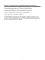
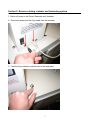
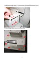
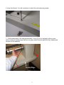
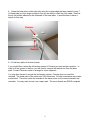
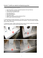
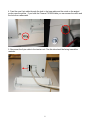
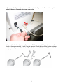
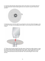
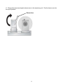
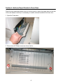
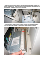
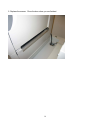
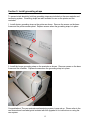
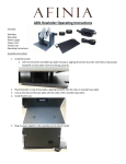
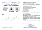
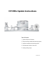
CX1200e Update Instructions
Table of Contents
1. Update software and firmware
2. Remove existing rewinder and tensioning system
3. Install new rewinder and tensioning system
4. Add new paper diverter to fuser door
5. Install grounding straps
511226-072309
Section 1: Update PTPrint, Status Monitor Software and Firmware
1. Before starting the update close PTPrint and the Status Monitor.
2. Make sure the CX1200e is online and connected to the network.
3. Insert the Installation disc that came with the update package.
4. Follow the prompts to complete the installation.
5. During the printer setup section you will be prompted to update your firmware. If your
CX1200e if offline or disconnected from your computer or network you will receive an error
message. If this update fails for this reason you can reattempt the firmware update after you
have restarted and reconnected the CX1200e.
2
Section 2: Remove existing rewinder and tensioning system
1. Switch off power to the Printer, Rewinder and Unwinder.
2. Disconnect power and the 6-pin cable from the rewinder.
3. Feed the 6-pin cable through the hole in the base plate.
3
4. Disengage the feeder switch (1) and disconnect the 6-pin cable from the tension unit (2).
1.
2.
5. Remove six #2 Phillips screws from the base plate.
4
6. Keep the Screws! You will need them to attach the new tensioning system.
7. Pull the base plate to the side approximately 1 inch (2.5 cm) or enough so that you are
able to create an overlap edge that you can grasp when lifting the plate with the rewinder and
tension unit still attached.
Overlap Edge
5
8. Grasp the base plate on the right side using the overlap edge that was created in step 7.
Lift base plate up at an angle enough so that you are able to reach the 6-pin cable. Remove
the zip tie holders adhered to the underside of the base plate. It would be best to have a
helper for this step.
Remove
Remove
9. Lift the base plate off and set it aside.
If you would like to return the old tension system to Primera you may use the same box. In
order to fit the system in the box, you will need to remove the tension unit from the base
plate. Contact Primera in order to arrange for return shipment.
You may also discard or recycle the old tension system. Primera does not need this
returned. The metal parts of the chuck are 100% aluminum. All other metal parts are powder
coated steel. The motor inside the rewinder is the same motor for the current rewinder and
unwinder. You may want to save it as a spare part. The circuit boards are ROHS compliant.
6
Section 3: Install new rewinder and tensioning system
1. Remove the following items from the box.
•
•
•
•
•
•
•
•
Label Guide Discs (inside the cardboard squares on the top of the box)
Chuck (inside the rectangular box)
Loctite and the 3mm allen wrench
Grounding Straps (2)
Paper Diverter Bracket
6-pin Cable (3 feet)
Updated User Manual and Quick Reference Sheet.
New rewinder and tensioning system.
2. Place rewinder and tensioning system on the frame in the same position as the old base
plate. Find a helper to help you lift and position the new plate. Line up the holes in the plate
with the holes in the frame.
3. Replace all 6 screws. Before replacing the two screws in the back, position the grounding
strap over the holes so that the screws secure them in place.
7
4. Feed the new 6-pin cable through the hole in the base plate and the notch on the angled
portion near the printer. If you have the Primera CX1200e table you can access the notch and
the hole from underneath.
5. Reconnect the 6-pin cable to the tension unit. The flat side should be facing toward the
rewinder.
8
6. Reconnect the 6-pin cable and power to the rewinder. Important! Connect the 6-pin
cable in the port closest to the power connector.
7. Locate the chuck and the 3mm allen wrench. Partially remove the two set screws on the
chuck so that approximately ½ inch (1 cm) is exposed. Crack the top off the Loctite container
and place two drops on each set screw. Reset each screw until it is flush with the outside of
the chuck.
9
8. Locate the label guide disc with the three interior holes. Remove the protective film from
the label guide discs. Attach the label guide disc to the rewinder using two flat head bolts
provided.
9. Attach the chuck to the drive shaft. Line up the holes in the chuck with the flat edges on the
drive shaft. The holes must correspond with the flats or the set screws will not hold the chuck
in place.
10. Tighten the set screws using the 3mm allen wrench. Once they are tight, attempt to rotate
the chuck forward backward while watching the drive shaft. The drive shaft should move with
the chuck. If it does not move with the chuck, loosen the set screws slightly and turn the
chuck until the set screws are even with the flats. The Loctite will begin to cure in a few
minutes.
10
11. Remove the tape securing the dancer arm to the tensioning unit. Flip the dancer arm into
the up/off position.
Dancer Arm
11
Section 4: Add new Paper Diverter to Fuser Door.
Since the new tensioning system does not have a switch to divert the paper feed out the side
of the unit instead of the top, it is necessary to install a diverter bracket on the fuser door.
1. Open the Fuser door.
2. Remove two #2 Phillips screws as shown below.
12
3. Be sure to remove the correct screws. The correct screws to remove are those that hold
down the metal door catch. When removing the screws make sure the catches remain in the
same positions. The bracket is installed over the catches.
Back Side
Front Side
4. Locate the Diverter Bracket. Position it over the end of the fuser door as shown below.
Push it into place so that the holes in the bracket line up with the holes in the door.
13
5. Replace the screws. Close the door when you are finished.
14
Section 5: Install grounding straps
To prevent static electricity build-up grounding straps are included on the new rewinder and
tensioning system. Grounding straps are also included for use on the printer and the
unwinder.
1. Install shorter grounding strap on the printer as shown. Remove the screws on the base
frame and the printer access panel. Replace screws when the grounding strap is in place.
2. Install the longer grounding strap on the unwinder as shown. Remove screws on the base
frame and the unwinder. Replace screws when the grounding strap is in place.
Congratulations! The new rewinder and tensioning system is now set up. Please refer to the
new manual and load label guide included with this upgrade kit for instructions on using the
new system.
15