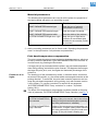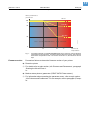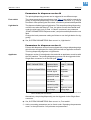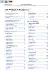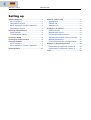
1
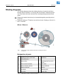
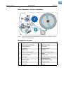
05/04 Rev. 3.00-01 USER MANUAL 64-xx – 64-xx dispenser Setting up Winding diagrams ......................................... 2 64-xx / Chess x ........................................ 2 Designation of parts .................................. 2 64-xx dispenser / Chess x dispenser ........ 3 Designation of parts .................................. 3 Selecting ribbon/material .............................. 4 Label material ............................................ 4 Thermotransfer ribbon ............................... 4 Inserting material .......................................... 5 Inserting fan-folded material ......................... 8 Changing material ......................................... 9 64-xx / Chess x ......................................... 9 64-xx dispenser / Chess x dispenser ........ 9 Inserting ribbon ........................................... 10 Material / Ribbon end ..................................11 Material end .............................................11 Ribbon end ..............................................11 Rewinder full ............................................11 Settings for all printers .................................12 Ribbon tension .........................................12 Material light barrier .................................13 Print head contact pressure .....................14 Adjusting the position of the print head ....15 Material parameters .................................16 Print head temperature compensation .....16 Settings for dispensing printers ...................18 Parameters for dispenser version M ........19 Parameters for dispenser version A ........19 Index ............................................................20 2 05/04 Rev. 3.00-01 USER MANUAL Setting Up 64-xx – 64-xx dispenser Winding diagrams The winding diagrams show the winding direction of material and ribbon through the 64-xx/Chess x or through the 64-xx/Chess x dispenser printer. You must follow this basic schema when inserting/changing material and ribbon. ¯ Ribbon and material should only be inserted/changed by specially trained personnel. P Advice on setting up TT4 printers can be found under “Setting up, Service” in the TT4 manual. 64-xx / Chess x 1 5 4 3 2 11 8 7 12 Z0124.cdr 10 6 13 14 9 Fig. 1: This is how to insert material and ribbon correctly in the 64-xx or Chess x. Designation of parts No. Designation No. Designation 1 Adjusting knob for print head contact pressure 8 Feed roller 2 Ribbon roller 9 Adjusting knob for punch sensor 3 Ribbon rewind mandrel 10 Pad rollers 4 Ribbon unwind mandrel 11 Ribbon deflector 5 Material unwinder 12 Opener 6 Print head 13 Material guide 7 Print roller 14 Dancer arm Tab. 1: Designation of parts on the 64-xx/Chess x. 3 05/04 Rev. 3.00-01 USER MANUAL Setting Up 64-xx – 64-xx dispenser 64-xx dispenser / Chess x dispenser 17 6 1 5 4 2 18 3 8 20 11 10 15 9 13 7 14 19 16 12 Fig. 2: This is how to insert material and ribbon correctly in the 64-xx dispenser / Chess x dispenser (each of type M). Designation of parts No. Designation No. Designation 1 Ribbon unwind mandrel 11 Dispensing edge 2 Ribbon deflector 12 Feed roller 3 Print head 13 Deflection roller 4 Ribbon roller 14 Rewinder 5 Ribbon rewind mandrel 15 Adjusting knob for punch sensor 6 Material unwinder 16 Locking lever 7 Dancer arm 17 Adjusting knob for print head contact pressure 8 Material guide 18 Clutch release motor 9 Feed roller 19 Rewinder motor 10 Print roller 20 Opener Tab. 2: Designation of parts on the 64-xx dispenser / Chess x dispenser. 4 05/04 Rev. 3.00-01 USER MANUAL Setting Up 64-xx – 64-xx dispenser Selecting ribbon/material Label material When selecting the material, you must take 3 factors into account: – the abrasive behavior of the surface structure of the material; – the properties with regard to the chemical reaction when printing ink is transferred; – the temperature required to transfer the ink. Abrasive behavior If the material is very abrasive, the print head becomes “worn down” quicker than would normally be the case. This criterion is of particular importance in thermoprinting. It is not so critical in the case of thermotransfer printing, as the ribbon can be chosen to be somewhat wider than the material, ensuring that the print head is protected across the entire width of the material. Head temperature The same applies if the temperature of the print head is high. Material and ribbon need longer to cool down, the print quality is more critical and the print head will wear down sooner. For papers with grammages greater than 240 g, it may be necessary to make adjustments with regard to the contact pressure and the position of the print head. Thermotransfer ribbon For ribbon, we recommend the following: – the reverse side of the ribbon must have an antistatic, friction-reducing coating (backcoating); – ribbons must be specified for “near edge type print heads”; – ribbons should be suitable for print speeds of up to 12 inch/sec. (300 mm/ s). ¯ Ribbon without these properties can reduce the performance of the printer and/or the print quality as well as damage the print head! 5 05/04 Rev. 3.00-01 USER MANUAL Setting Up 64-xx – 64-xx dispenser Inserting material 1 CAUTION! Rotating axles! These can pull in and tear off hair, clothing and jewelry. – Do not operate the machine with the hood open! – Keep long hair, loose clothing, jewelry etc. well away from the machine! • 64-xx/Chess x standard unit: Steps 1 to 8 • 64-xx/Chess x dispenser version: Steps 1 to 18 2 1. Open the hood of the unit. 2. Pull off the outer guide disk (1) of the unwinder (2). 3. Creel material on the unwinder with the corresponding adapter rings. The roll of material should turn anti-clockwise when unwinding. 4. Refit the outer guide disk of the unwinder. 3 5. Lay material around the dancer arm. 6. Set the material guide to the width of the label material. To do this, loosen the knurled screw on the underside of the front material guide (3). Push the material guide sideways. Tighten the knurled screw again (Fig. 2). 7. Press the red opener (4) of the intake in order to raise the pad rollers. With the opener depressed, push the start of the material through the material guide until it is below the print head (Fig. 3). 8. Align the material so that it is taken in straight. With the loading lever depressed, position the pad rollers of the printing unit in such a way that both rollers (5) sit symmetrically on the material. (The print head has been removed in Fig. 4 to allow a better view). 4 6 05/04 Rev. 3.00-01 USER MANUAL Setting Up 64-xx – 64-xx dispenser Only dispenser version: 1 9. Guide material through under the dispenser roller (1). 10. Pull labels off the backing paper over a length of about 50 cm (Fig. 1). 11. Open the locking lever (press downwards, Fig. 2) and swivel it half a revolution to the rear. 12. Pull the drawing module (2) all the way out (Fig. 3). 13. Guide the backing paper under the print module to the rear (Fig. 4). 2 P Continued on next page. 3 4 7 05/04 Rev. 3.00-01 USER MANUAL Setting Up 64-xx – 64-xx dispenser 14. Guide the backing paper around the feed roller (1) and guide pins (2) of the drawing module to form an S shape (Fig. 1). 1 15. Put the drawing module back in again (Fig. 2). ¯ On insertion, it is essential that the locking lever points to the right (= half a revolution open). Do not lock it until the drawing module has been pushed in all the way to the limit stop! 16. Wind the end of the backing paper clockwise around the rewinder (3) and fix with the clip (4) (Figs. 3 and 4). 2 17. Position the block bearing the pressure roller (5) in the middle of the backing paper. ¯ This is important for proper transport of the backing paper around the dispensing edge! 18. Lock the locking lever (Fig. 4). 3 4 8 05/04 Rev. 3.00-01 USER MANUAL Setting Up 64-xx – 64-xx dispenser Inserting fan-folded material 1. Set the outer disc of the material unwinder to the width of the material. 2. Pull the material through the inlet opening (1) to the material guide with the side to be printed showing upwards. 3. Then proceed as described in section Inserting material on page 5. Fig. 1: Pull the fan-folded material through the inlet opening in the rear side and proceed then as described under „Inserting material“. 9 05/04 Rev. 3.00-01 USER MANUAL Setting Up 64-xx – 64-xx dispenser Changing material 1 Proceed as described in the following to replace an inserted material roll befor it comes to an end. ¯ The printer must be switched on; otherwise, the printhead presses on the material. 64-xx / Chess x 1. Switch the printer to offline mode and open the front hood. 2. To remove the material, press the opener while at the same time pulling the material away to the rear (Fig. 2). 2 64-xx dispenser / Chess x dispenser 1. Switch the printer to offline mode and open the front hood. 2. Tear the backing paper off (2), pull out the clip (Fig. 3) and remove the wound up backing paper (Fig. 4). 3. Open the shutter (3) and pull out the remaining backing paper towards the dispensing edge. 4. To remove the material, press the opener while at the same time pulling the material away to the rear (Fig. 2). ¯ It is also possible to convey the material backwards out of the print module by pressing the Online+Cut keys in offline mode. 3 10 05/04 Rev. 3.00-01 USER MANUAL Setting Up 64-xx – 64-xx dispenser Inserting ribbon 1 1. Switch the printer on. 2. Open the hood of the printer. 3. Place the roll of ribbon on the right ribbon mandrel (1) so that it can unwind anti-clockwise. 4. Place the empty ribbon core on the left mandrel (2). 5. Lead the end of the protective ribbon (yellow here) under the ribbon deflector (3) and print head (4). 6. Then pull the (protective) ribbon upwards and lay it over the ribbon roller (5). 2 7. Lead the (protective) ribbon under the rewinder mandrel (2) and secure it on the empty ribbon core using the selfadhesive strip (6) (Fig. 3). ¯ In many types of ribbon, the protective ribbon (shown in yellow in the illustration) is followed by a strip of cleaning ribbon (7) which serves to remove contamination from the print head. It is essential that the material is inserted as described so that the cleaning effect is guaranteed! 3 8. Check that the ribbon is free of folds and is running true. Tension the ribbon by hand if necessary. 4 11 05/04 Rev. 3.00-01 USER MANUAL Setting Up 64-xx – 64-xx dispenser Material / Ribbon end Material end If the material end has passed the material guiding, the following status message appears: Status Material end 5002 1. Press the opener and pull the remaining material from the front side (display side) out of the print unit. 2. Only dispenser version: Open the shutter and pull the remaining backing paper in direction rewinder out of the print unit. 3. Take the clip off the rewinder and remove the wound up backing paper. P For additional information read section Changing material on page 9. Ribbon end If the ribbon roll is emptied, that is the ribbon unwinding mandrel stopped turning, the following status message appaers: Status Ribbon end 5008 £ Proceed as described in section Inserting ribbon on page 10. P The ribbon end detection can be switched off, e.g. for thermal printing. £ To do so, set the parameter „SYSTEM PARAMETERS/ Ribbon autoecon.“ to „thermal printing“. Rewinder full ¯ Only for dispenser versions! The dispenser rewinder can wind up the backing paper of a roll with 210 mm outer diameter and 4“ (102 mm) core inner diameter. If the maximum capacity of the rewinder is reached, the following status message appears: Status Rewinder full 5064 £ Proceed as described in section Changing material on page 9. ¯ Best clear the rewinder after every printed material roll! 12 05/04 Rev. 3.00-01 USER MANUAL Setting Up 64-xx – 64-xx dispenser Settings for all printers Ribbon tension The torques of the ribbon unwind mandrel (1) and ribbon rewind mandrel (2) can be set using the red plastic hexagons on the ribbon mandrels. If these are turned clockwise, the torque increases (Fig. 1: dispenser version). Factory settings The factory setting covers a wide range of different ribbon widths, but very narrow or very wide ribbons may necessitate readjustment. Setting During feeding, the ribbon must run evenly and free of folds for the entire length between the mandrels. The following guidelines will facilitate setting: The ribbon is loose or creased or is wound on the rewind mandrel too loosely. £ Increase the unwind/rewind torque (Turn the red hex nut clockwise). The ribbon visibly stretches or tears during printing. The ribbon is inadequately transported. £ Decrease the unwind/rewind torque (Turn the red hex nut counter clockwise). P More details about setting the ribbon tension can be found under “Adjusting the ribbon brake” in the “Service print module” section of the 64-xx service manual. 1 13 05/04 Rev. 3.00-01 USER MANUAL Setting Up 64-xx – 64-xx dispenser Material light barrier The series 64-xx / Chess-xx machines are fitted with transmitted-light light barriers. Reflector light barriers are also available as an option. To set Setting is performed by means of the red rotary knob (1) on the outside of the print module. The light barrier can be adjusted in a range of 15 mm transverse to the material by turning the rotary knob. A dial (2) shows the setting value from 0 to 15. Fig. 1: Setting value The red adjusting knob (1) is used to adjust the lateral position of the punch light barrier (figure: dispenser version). Light barrier Setting value = Transmitted light Punch position - 2 mm Reflector Punch position - 13 mm Tab. 1: How to determine the setting value for the punch light barrier. (Punch position = distance of punch center from (inner) edge of material (3); setting value = dial value to be set by turning the red wheel) Fig. 2: Punch position = distance of punch center from (inner) edge of material (3). £ To set, turn the rotary knob (1) until the desired setting value is opposite the marking. Example (for transmitted-light light barriers) center of punch from left edge = 11 mm, from which 2 mm deducted, giving a setting value of 9 mm. ¯ For round labels, it is possible to perform a preliminary setting of the punch offset manually on the printer (parameter “X – print offset”) or by activation in order to capture the start of the labels correctly. 14 05/04 Rev. 3.00-01 USER MANUAL Setting Up 64-xx – 64-xx dispenser Print head contact pressure 1 Different material widths and/or material thicknesses have an effect on the contact pressure of the thermal strip on the feed roller. The contact pressure can be set in 3 steps: I Position for thin/narrow material (1) II Position for average material (2) III Position for thick/wide material (3) To set: The red adjusting screw (4) sits above the ribbon roller and can be turned by means of a coin. 2 £ For medium head contact pressure, turn the arrow to position II until it engages. £ For greater head contact pressure, turn the arrow to position III until it engages. ¯ Always choose the lightest contact pressure that will produce an acceptable printing result. This will help to protect the print head and the entire unit. ¯ Excess contact pressure can lead to premature wear on the print head. Factory setting: Position 1, thin/narrow material 15 05/04 Rev. 3.00-01 USER MANUAL Setting Up 64-xx – 64-xx dispenser Adjusting the position of the print head 1 ¯ Only for the standard version of 64-05/06/ 08 and Chess 5/6/8! The print head 0 line can be adjusted variably from 2 mm (from the left edge of the label) to 13 mm: 1. Loosen both thumb screws (1) and push the print head to the desired position. ¯ The print head does not have to be taken off! 2. Tighten the screws again. 3. Loosen the stud screws at the black plastic disks (2) using a 2 mm allen key (one screw per disk). 4. Adjust the plastic disks to the same position as the inside of the print head. 5. Tighten the stud screws again. 2 16 05/04 Rev. 3.00-01 USER MANUAL Setting Up 64-xx – 64-xx dispenser Material parameters The following three parameters are used to tell the printer the properties of the label material with which you would like to work: Parameter Function PRINT PARAMETER/material type Sets the type of material (punched or continuous) PRINT PARAMETER/material length Sets the length of material PRINT PARAMETER/material width Sets the width of the material SYSTEM PARAMETER/light sens. type Sets the type of light barrier (reflector or transmitted light) suitable for the material (marks or punches) Tab. 1: Important parameters for setting material properties P Advice on setting parameters can be found under “Operating the parameter menu” in the topic section “Info printouts and parameters”. Print head temperature compensation The print contrast depends strongly on the print head temperature, which can be set by means of parameter „SYSTEM PARAMETERS/ Print contrast“ or, in online mode, by pressing the Esc button. If a large print job is proceeded with the printer, the print head temperature rises during printing, and with it the print contrast. This happens the stronger, the larger the print job is, and, the higher the blackened percentage of the printout is. Firmware 2.45 or higher ¯ The heating up of the printhead may smear, in extreme cases, some tinier structures of the printout, e.g. bar codes which are arranged crosswise to the printing direction. To avoid this, the print head controller measures and corrects the print head temperature during printing (only with firmware version 2.45 or higher). To use the correction it is required to set parameter „SYSTEM PARAMETERS/ Temp. reduction“ to a value > 0 (Default setting: 20%). The effect of the temperature compensation increases parallel to the rising value of parameter „SYSTEM PARAMETERS/ Temp. reduction“ (see Fig. 1). Parameter Function SYSTEM PARAMETERS/ Print contrast Setting of the print contrast, that is the indirect setting of the print head temperature (actually, the drive performance is modified). SYSTEM PARAMETERS/ Temp. reduction Setting of the temperature compensation correction factor. A higher setting value reduces the drive performance of the print head more strongly (if the print head is heating up). Tab. 2: Important parameters for setting the print contrast. 17 05/04 Rev. 3.00-01 USER MANUAL Setting Up 64-xx – 64-xx dispenser Drive performance print head TR=0 100 % TR=20% 80 Z0141E.cdr TR=60% 40 TR = “SYSTEM PARAMETERS / Temp. reduction” 0 26 Fig. 1: Firmware version 54 °C Print head temperature Activating parameter „SYSTEM PARAMETERS/ Temp. reduction“ reduces the drive performance of the print head - and with it indirectly the print contrast. The reduction starts when a temperature of 26°C is reached. From 54°C on, the maximum value is kept. Proceed as follows to detect the firmware version of your printer: £ Reset the printer P For details refer to topic section „Info Printouts and Parameters“, paragraph „Starting the 64-xx/Chess x“. or: £ Make a status printout (parameter „PRINT INFO/ Printer status“). P For information about operating the parameter menu, refer to topic section „Info Printouts and Parameters“. For an example, refer to paragraph „Example“. 18 05/04 Rev. 3.00-01 USER MANUAL Setting Up 64-xx – 64-xx dispenser Settings for dispensing printers ¯ Only valid for the dispenser versions! The 64-xx or Chess x respectively is optionally delivered as Dispenser M or Dispenser A version. The versions are designed for different cases of application (see Tab. 3:). Application Dispensing edge Single-Start USI inter- Foot connector face switch 64-xx dispenser M Printing/dispensing is short, with triggered manually. The light barrier dispensed labels are taken off by hand. optional optional 64-xx dispenser A Printing/dispensing is long, without triggered by a signal of light barrier the USI. Taking off the dispensed label by hand or by an applicator. optional optional Tab. 3: Different configuration of Dispenser M and Dispenser A. Basic setting The following table (see Tab. 4:) shows a basic setting for those parameters which are most important for dispenser operation. The setting is as well for type M as for type A with the purpose of using a foot switch. The two dispenser versions differ from each other in the parameters provided in the parameter menu. Type A has - with the optional USI interface installed additional parameters for setting the USI (submenu „DP INTERFACE). Submenu Parameter Setting PRINT PARAMETERS Dispense Mode Real 1:1 Mode Dispensposition 0 mm SYSTEM PARAMETERS Periph. device Dispenser External signal Singlestart Dispensing mode fast Application mode manual Start mode Edge Start source Foot switch Dispensing edge short Transport mode Dispenser motor Signal edge Falling edge Tab. 4: Basic setting of the parameters most important for dispenser operation - valid for both dispenser versions. P Advice on setting parameters can be found under “Operating the parameter menu” in the topic section “Info printouts and parameters”. 19 05/04 Rev. 3.00-01 USER MANUAL Setting Up 64-xx – 64-xx dispenser Parameters for dispenser version M The printing/dispensing process can be triggered in two different ways: Foot switch The values preset by the manufacturer (see Tab. 4:) are valid for manual triggering of the printing/dispensing via the Single-Start connector, e.g. using a foot switch. After pressing the foot switch, one label is printed and dispensed. Light barrier The dispensed label triggers a light barrier. This stops the printing/dispensing until the user takes the label off. Then, the printer moves the material back under the print head (only if „Real 1:1 Mode“ is selected, see parameter „PRINT PARAMETERS/ Dispense mode“) and prints and dispenses the next label. Change the basic parameter setting as follows to use the light barrier for triggering: £ Set „SYSTEM PARAMETERS/ Start source“ to „Light barrier“. Parameters for dispenser version A Printers with dispenser version A are equipped with a longer dispensing edge which leaves enough space for closing the hood with an applicator mounted. This long dispensing edge has no light barrier. Applicator Dispenser version A is designed to be used with an applicator as well as with the USI interface. The printing/dispensing process can be triggered via the Single-Start connector or via the USI (see Tab. 5:). Submenu Parameter Setting PRINT PARAMETERS Dispense Mode Echter 1:1 Modus Dispensposition 0 mm SYSTEM PARAMETERS Periph. device Dispenser External signal Singlestart Dispensing mode fast Application mode LTS 80/200 Start mode Edge Start source USI Dispensing edge long Transport mode Dispenser motor Signal edge Falling edge Tab. 5: Basic setting for dispenser version A - To be used with applicator (here: Licht Touch Sensor 80/200) and USI interface. Alternatively, the printing/dispensinig can be triggered via the Single-Start connector: £ Set „SYSTEM PARAMETERS/ Start source“ to „Foot switch“. P Advice on setting parameters can be found under “Operating the parameter menu” in the topic section “Info printouts and parameters”. 20 05/04 Rev. 3.00-01 USER MANUAL Setting up 64-xx – 64-xx dispenser Index P C Print contrast 16 Print head temperature 16 Changing material 9 D Designation of parts - 64-xx dispenser, Chess x dispenser 3 - 64-xx, Chess x 2 Dispenser - parameters for version A 19 - parameters for version M 19 - Rewinder full 11 Drawing module 7 F Fan-folded material 8 I Inserting Material 5 Inserting ribbon 10 L Label material 4 M Material end 11 R Ribbon end 11 S Setting label material parameters 16 Setting the material light barrier 13 Setting the position of the print head 15 Setting the print head contact pressure 14 Setting the ribbon tension 12 T Temperature compensation 16 Thermoprinting ribbon 4 W Winding schema - Dispenser version 3 - Standard version 2