1
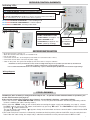
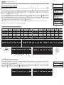
RECEIVER CONTROL ELEMENTS
Indicating LEDs:
GREEN LIT UP - electrical power connection on
BLUE SHORT BLINKING - sending or receiving a signal
RED BLINKING - empty E-EPROM memory
RED LIT UP - FAILURE Error mode (if no signal is received from the transmitter in
6 hours, will switch to a2 min. ON and 8 min. OFF sequence)
BLUE+RED BLINKING ALTERNATELY - code learning mode
BLUE+RED BLINKING CONCURRENTLY - code accepted
BLUE+RED LIT TOGETHER - memory erase mode
ORANGE LIT UP - relay is switched on
Front cover lift of:
Fig.1
Fig.2
Holes for installation on KU/KP68
FUNCTION BUTTON
- SHORT PRESS (for approx. 1 s)
CODE LEARNING mode
- LONG PRESS (for apprrox. 3s)
RESET (memory clearing)
output terminals
for boiler
(potential-free
switching
contact)
power supply
terminals
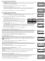
RECEIVER INSTALLATION
-
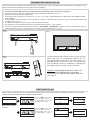
lift off the front cover, see Figs 1,2
attach the receiver to the wall (or to an installation box)
turn off main switch
connect the receiver acc. to the diagram (use terminals for room thermostat - 2 wires)
connect the receiver to the 230 V/50 Hz power supply
switch on the power. The green LED will light up and the receiver is ready for activation
Install the receiver (in internal rooms) as far from big metal objects as possible (at least 0.5 m) and far from
power lines owing to interference of the signal received!
It is recommended that the device is installed by a person with adequate qualification in electrical engineering!
Wiring diagram:
BOILER
L
N
230 V/50Hz
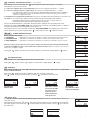
CODE LEARNING
The BPT322 GST assembly is configured and ready to use – to put the receiver and transmitter in operation, just
use the TEST function (see page 5)!
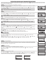
If the receiver memory has, however, been cleared – the red diode is flashing – proceed as follows:
1) Press the receiver’s “FUNCTION BUTTON” for about 1.5 sec; the yellow and red LEDs start flashing alternately; and the
receiver is awaiting the code (“learning mode“).
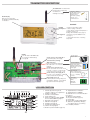
2) Press twice the “ MENU “ button on the receiver (after connecting the power supply and activating, see page 3), choose
the TEST mode by turning the“ “ button, and confirm it by pressing “ “button. The TEST RFM message is displayed,
by turning “ “ button start the test.
The sign for wireless transmitting “
“ appears shortly on the transmitter and once communication is established the RFM
sing will lit permanently.
3) The code receipt in the receiver is indicated by simultaneous flashing of the yellow and red LEDs; thus the code has been
learnt. After the code receipt, the output relay is switched several times to verify correct function of BPT322 GST.
2