1
Océ Graphics
Server L
Startup Manual
Océ-Technologies B.V.
Trademarks
Products in this manual are referred to by their trade names. In most, if not all
cases, these designations are claimed as trademarks or registered trademarks of
their respective companies.
Copyright
Océ-Technologies B.V. Venlo, The Netherlands © 1999
All rights reserved. No part of this work may be reproduced, copied, adapted,
or transmitted in any form or by any means without written permission from
Océ.
Océ-Technologies B.V. makes no representation or warranties with respect to
the contents hereof and specifically disclaims any implied warranties of
merchantability or fitness for any particular purpose.
Further, Océ-Technologies B.V. reserves the right to revise this publication and
to make changes from time to time in the content hereof without obligation to
notify any person of such revision or changes.
Code number 7055891
Edition 1.2
US
Table of Contents
Chapter 1
Read Me First
Introduction 8
What is Océ Graphics Server L? 8
Océ Graphics Server L RIP 8
Océ Graphics Server L on the network 8
Océ Graphics Server user documentation 9
Installation Manual 9
Start Up Manual 9
Reference Manual 9
Online Help files 10
How to use this manual 11
Chapter 2
Printing from an application
Settings from within the PostScript Printer Description (PPD) 14
Printing from Windows applications 16
Printing from Apple Macintosh applications 18
Chapter 3
Printing from Océ Graphics Server
Starting the Océ Server 22
Receiving jobs in spool queues 23
Printers ready to receive print jobs 23
Automatically starting print jobs 24
Printing individual jobs 25
Printing a job from a spool queue 25
Printing a job that is not in a spool queue 26
Changing settings for an individual print job 27
Adding a PostScript or bitmap file to a spool queue 28
Rearranging jobs in queues 29
Deleting jobs from queues 30
Controlling the Server main screen from a workstation 30
Table of Contents
3
Chapter 4
Optimizing printing
Opening the Printer Setup dialog box 32
What is a printer configuration? 32
Selecting a printer configuration 33
Specifying a printer paper source 34
Enlarging and reducing the image size 35
Rotating the image 39
Positioning the image on paper 39
Cropping an image 41
Changing units 43
Changing your view of the paper 43
Chapter 5
Tiling and Cropping
Loading a job into Tile and Crop 46
Changing measurement units 47
Specifying final image size 48
Specifying tile size 49
Cropping an image 50
Printing tiles 51
Setting custom paper sizes 53
Editing a tile and crop file 54
Chapter 6
Monitoring status and log files
Server status 56
Viewing the current status of the server 56
Viewing the current status of a job being printed 57
Changing settings for an individual print job 57
Viewing printing histories 58
Searching for specific printing histories 61
Printing search results 63
Including previewed jobs in searches 63
Searching for printing histories on your system 64
Creating log files and setting options 65
4
Océ Graphics Server L Startup Manual
Chapter 7
Using the Remote RIP Software
General Features 68
What does Remote RIP Client enable me to do? 68
What does Remote RIP Server enable me to do? 68
Using Remote RIP Server software 69
Starting the Océ Server Remote RIP Server 69
Setting the Administrator and the Power User passwords 71
Client workstations currently connected 74
Sending messages to Client workstations 74
Disconnecting Client workstations 76
Hide Server option 77
Change Scanned Image Location option 77
Stopping the Server 79
Using Remote RIP Client software 80
Opening the Server Remote Client Window 80
What can I do as a Guest User? 82
Logging on as a Power User 86
What can I do as a Power User? 88
Appendix A
Miscellaneous
How to read this manual 92
User survey 93
Addresses of local Océ organizations 95
Index 97
Table of Contents
5
6
Océ Graphics Server L Startup Manual
Océ Graphics Server L
Startup Manual
Chapter 1
Read Me First
This manual has been written to guide you through the
basic tasks you will carry out using Océ Graphics Server
L. It is intended for all users.
7
Introduction
What is Océ Graphics Server L?
Océ Graphics Server L is a powerful software application that allows you to
print full color PostScript and bitmap files to your Océ 5350 inkjet printer.
Océ Graphics Server L RIP
Océ Graphics Server L is a Raster Image Processor (RIP). Its main function is
to receive the complex descriptions of pages with integrated text, graphics and
images that comprise PostScript files and translate each page into a format that
is understood by your printer.
Océ Graphics Server L on the network
Océ Graphics Server L also acts as a print server. It allows you to send
drawings from a Windows PC or Macintosh workstation to a print queue on the
server workstation, from which the files are submitted to the printer.
You can create up to 14 print queues for each Océ 5350 printer connected to
the Server workstation and publish them over the network.
[1] Océ Graphics Server L on the network
8
Océ Graphics Server L Startup Manual
Océ Graphics Server user documentation
Océ Graphics Server L includes the following set of user documentation. Since
not all users are interested in knowing how to use all aspects of the software,
the following summary indicates which parts of the documentation are
probably most relevant to different types of users.
Installation Manual
The installation manual explains how to install the Océ Graphics Server L
software on your server workstation. It also explains how to connect your
server to your network and how to set up workstations on the network so that
they can send files to the server to be printed. It is intended for:
■
systems administrators or advanced users responsible for setting up the
Server workstation and the client workstations on the network.
Start Up Manual
This manual explains the basic features of Océ Graphics Server L that most
users will need to know. It is aimed at two types of user:
■
■
users who are connected to the Océ Server on the network and need to know
how to print a file to the spool queue from their workstation
users who will be using Océ Graphics Server L from the Server workstation
and need to know how to use the main features of the Océ Server.
Reference Manual
This manual explains the advanced features of Océ Graphics Server L and is
intended for:
■
advanced users who will be using the Océ Server from the Server
workstation and will be dealing with issues such as color calibration, setting
up spool queues and creating printer configurations
Read Me First
9
■
■
systems administrators responsible for setting up and configuring the Océ
Server workstation and setting up the Server to be used over the network
advanced users dealing with PostScript programming and troubleshooting.
Online Help files
Océ Graphics Server L has its own Windows online Help file. Once the
software has been correctly installed, you can consult the online Help if you
need a quick explanation of a menu or dialog box option or a task to perform.
▼
To open the Océ Server Help file
■
■
■
Click on a Help button in a dialog box or
Choose Index from the Help menu in the main window of the Océ Server or
Choose the Océ Server Help icon from the Océ Graphics Server program
folder
Océ Graphics Server L also has an online Quick Start Guide tutorial intended
for new users who would like an introduction to the product. It explains just the
main features of Océ Server and contains step-by-step procedures for carrying
out some basic tasks with the software.
▼
To open the Quick Start Guide
■
10
Choose the Quick Start Guide icon from the Océ Graphics Server program
folder
Océ Graphics Server L Startup Manual
How to use this manual
This manual is divided into the following chapters:
Chapter 1 - Read Me First introduces you to the product and explains how to
use the user documentation in general and this manual in particular.
Chapter 2 - Printing from an application describes how to print a PostScript
file from an imaging application to Océ Graphics Server L from an Apple
Macintosh or Windows PC workstation.
Chapter 3 - Printing from Océ Graphics Server describes how to use the basic
features of the Océ Graphics Server main window and how to manage and print
files arriving in spool queues.
Chapter 4 - Optimizing printing describes how to set printing options such as
paper source, image rotation and scaling from the Océ Server main window.
Chapter 5 -Tiling and Cropping describes how to use the Tile and Crop
module built into the Océ Server for preparing and printing out tiles that will
later be assembled to make up very large format posters and wall coverings.
Chapter 6 - Monitoring status and log files explains how to use the features of
Océ Server that allow you to keep track of your files and workload.
Chapter 7 - Using the Remote RIP software explains how to use the Remote
Océ Server RIP software module, which allows client workstations on the
same network as the Océ Server to see the main Server window directly.
Appendix - Miscellaneous contains a list of Océ offices worldwide and a
reader’s comment sheet.
Index - A quick reference section.
Read Me First
11
12
Océ Graphics Server L Startup Manual
Océ Graphics Server L
Startup Manual
Chapter 2
Printing from an application
This chapter explains how to send files to the Océ Server
from graphics and word processing applications on your
Windows PC or Apple Macintosh network workstation.
13
Settings from within the PostScript Printer Description (PPD)
From Macintosh or PC workstations, you can select the following options from
the PPD at print time. Each setting affects the corresponding value at the RIP
for that job only. It does affect values unless you specify so from within OGSL.
▼
To make settings from within the PPD
1 From the Windows Start menu, select Settings, then Printers.
2 Select the printer and right-click to display a short-cut menu.
3 Select Document defaults.
4 Click the Advanced tab and go to Document options in the arborescence.
5 Select PostScript options. The following window displays the available
options:
14
Océ Graphics Server L Startup Manual
PPD options/settings
Function
Screen type
Selects a different screening option
Standard
Error Diffusion
■ FM
■ Normal Inkjet
■ Adjusted Inkjet
■ 400 dpi Electro
■ 200/300 dpi Electro
■
■
Note: When printing to the Océ 5350, select
“adjusted inkjet”, as all profiles delivered with the
printer are optimized for this screening method.
Combine separations
■
■
On: applies the same plate order as specified in the RIP settings
Off
Output method
Direct to printer: sends data to the printer as it is processed
Save to file then print: saves the processed file in a temporary buffer
directory before sending it to the printer
■ Print via REPRINT: stores the file in a special format for post-printing
Percentage scaling
Selects a scaling factor for a single print
■ PercentageScale1000
Example: If you select 0 from 1000’s, 3 from 100’s,
■ PercentageScale100
7 from 10’s, and 5 from 1’s, you get a 375% scaling
■ PercentageScale10
factor for that print only.
■ PercentageScale1
Rotate by
Rotates the print job from the PPD
■ 0, 90°, 180°, 270°
Print Mirrored
Mirrors the print job
■ On
■ Off
Crop Marks
Adds crop marks to the print (from PPD only)
■ Off
■ Outline: draws a dotted outline around the image (outside print area)
■ Corners: draws normal corner crop marks (outside print area)
■ OutlineWithinPrintArea
■ CornersWithinPrintArea
■
■
Marks position
MarksOutsidePrintArea: places crops on the edge of the image
MarksInsidePrintArea: places crops 3mm inside the image to simulate
bleed
■
■
Printing from an application
15
PPD options/settings
Function
Adds text under the image
No text
■ Print Job Name
■ Print Date and Time
■ Print Job Name and Date and Time
Print Job Title
■
▼
To keep modified settings
1 In the OGSL main window, right-click the printer icon and select Properties.
2 Select the Output tab.
3 Enable the option 'Allow jobs to control printer via PPD settings'.
Printing from Windows applications
Note: In order to print to the Océ Server from your workstation, the PostScript
Printer Definition files (PPDs) which describe the Océ Server to your
application must be installed on your workstation. The Océ Graphics Server L
Installation Manual contains instructions for installing the appropriate
software and setting up workstations.
When you are ready to print to the Server from within your application, select
Page Setup and then Print.
For example:
16
Océ Graphics Server L Startup Manual
Suppose you have created a printable file in Microsoft Word Version 6.0. First
select Page Setup from the File menu to specify Margins, Paper Size, Paper
Source and Layout.
Then select Print from the File menu to specify print details, such as the
number of copies required and page ranges.
Printing from an application
17
The Print dialog box contains a Printer… button. Click on this button to display
the Print Setup window where you can select and set the appropriate Océ
Server printer as the default printer.
Once you have set an Océ Server printer as the default printer, click on OK in
the Print dialog window to automatically print your file to the Server spool
queue for that printer.
Printing from Apple Macintosh applications
Note: The Océ Server is supplied with an Apple Macintosh Printer Drivers
disk. This contains all the PostScript Printer Definitions (PPDs) and Printer
Description Files (PDFs) necessary to set up most available applications on
the Macintosh. These must be installed on your workstation before you can
print to the Océ Server. Instructions for installing this disk are in the Océ
Graphics Server L Installation Manual.
When Services for Macintosh are installed on the Océ Server, any printer
queue set up in the Océ Server is automatically published to a Macintosh
workstation through the Chooser. Select the LaserWriter 8.x printer driver and,
if your network has zones, the AppleTalk zone. The Server print queues will
appear on the right side of the Chooser under the heading 'Select a PostScript
Printer'. Select an Océ Server print queue, click on the Chooser Setup button
and then select the Océ 5350 Large Format PPD.
Return to your application. To send your job across the network to the Server,
first select Page setup and then Print.
18
Océ Graphics Server L Startup Manual
For example:
Suppose you have created a printable file in QuarkXPress. Open the file in
QuarkXpress and select Page Setup from the File menu.
Click on the OK button to save your settings.
Then select Print from the File menu to open the 'Printer:' dialog box.
Click on the Print button to print your job across the network to the Océ Server.
Printing from an application
19
20
Océ Graphics Server L Startup Manual
Océ Graphics Server L
Startup Manual
Chapter 3
Printing from Océ Graphics Server
This chapter explains how to print files manually and
automatically from the Océ Graphics Server and how to
manipulate jobs in spool queues.
21
Starting the Océ Server
Installing the programs from the Océ Server Program Installation CD creates
an Océ Server entry on your machine. (For details of how to install the
programs, please see the Océ Graphics Server L Installation Manual.)
1 Click on the Start menu and choose Programs.
2 Choose the Océ Graphics Server L in the Océ Graphics Server L folder to start
the Océ Server and display the main screen.
1. Menu bar
2. Button Bar
3. Print Queue Icon Bar
4. Job Information Bar
5. Active Jobs List
6. Inactive Jobs List
7. Settings Icon
8. Status Bar
22
Océ Graphics Server L Startup Manual
Receiving jobs in spool queues
The middle section of the Océ Server main screen displays the Active Job
List (5) and the Inactive Job List (6).
All jobs that arrive in one of the spool queues are displayed in the Active Job
List (jobs waiting to be printed) by default.
Once printed, the Océ Server sends a job to the Inactive Job List by default.
(Jobs displayed in the Inactive Job List have either been printed or are on hold.)
Information about each job is displayed, such as its name, size, printer, date
and time of arrival in queue.
Printers ready to receive print jobs
Each icon displayed in the Print Queue Icon Bar represents a printer. The
presence of the icon in the Bar means that the device represented has a spool
queue assigned to it and is set up ready to receive print jobs.
This icon in your Print Queue Icon Bar represents the Océ Server Previewer.
The Previewer does not produce hard copy printouts but displays files spooled
to it on screen for you to preview.
Printing from Océ Graphics Server
23
Automatically starting print jobs
The Océ Server will automatically send any files found in the Active Job List
to the appropriate printer when the spooler is started.
Click on the START button on the Button Bar (2) to start the Server spooler.
Click on the STOP button on the Button Bar when you want the Server to
complete the current job but accept no more jobs from the Active Jobs list.
Click on the PAUSE button on the Button Bar when you want to pause the
automatic printing process. The Server will complete the processing of an
image but will not send it to the printer. If a job was printing, the Server will
complete that image but will not send additional copies. When PAUSE is
selected, a dialog box opens on screen, prompting you to select OK when you
wish to continue.
Click on the ABORT button on the Button Bar and push the RESET button on
the printer console when you want to cancel the current job. The Server will
then continue with the next job in the Active Jobs list.
You can also Start and Stop the Océ Server spooler by clicking on Spooler in
the Océ Server Menu Bar (1) and selecting Start Spooler and Stop Spooler
from the drop-down menu.
24
Océ Graphics Server L Startup Manual
Printing individual jobs
This is useful if you need to print an individual job manually.
Printing a job from a spool queue
When the individual job you wish to print is in a spool queue, it will be stored
in either the Active Jobs List or the Inactive Jobs List. You then have three
ways of printing it manually from within the Océ Server main screen:
▼
The drag-and-drop method
Select the job you wish to print by clicking on it. Then drag and drop the job
onto the Print Queue icon representing the printer you want to print the file to.
This method also allows you to select several jobs at the same time.
▼
The do… button method
1 Click on the do… button beside the name of the job you wish to print.
2 Select Print File from the do… button drop-down menu.
The Océ Server will send the job to the printer for which the job is queued.
▼
The Print File button method
1 Select the job you wish to print by clicking on it.
2 Click on the Print File button in the Océ Server Button Bar. The Océ Server
will send the job to the printer for which it is queued.
Printing from Océ Graphics Server
25
Printing a job that is not in a spool queue
When you wish to print a PostScript file located on a floppy disk or elsewhere
on the network, you can still find and print it from within the Océ Server main
screen.
▼
The Print Queue icon method
1 Click the Print Queue icon representing the printer you wish to print the file to.
2 Select Print File from the drop-down menu.
An 'Open and Print EPS File' dialog window will appear.
3 Locate and select the file you wish to print.
4 Click on the Open button.
The Océ Server will interpret and send the file to the printer.
▼
The Print File button method
1 Make sure there are no jobs selected in the Active and Inactive Jobs Lists.
2 Click on the Print File button in the Océ Server Button Bar.
The 'Open and Print EPS File' dialog window will be displayed.
3 Locate and select the file you wish to print and click on the Open button.
The Server will interpret and send the file to the printer to which the first spool
queue set up has been assigned.
26
Océ Graphics Server L Startup Manual
Changing settings for an individual print job
Click on the do… button for the individual job and select Change Settings from
the drop-down menu of options. Any settings made via this option are specific
to the individual job associated with the do… button you click on.
The 'Job Settings For' dialog box opens. This box shows all the header
information for that job and allows you to make three job-specific settings.
To specify the number of copies to be printed Check the Force copies to:
checkbox and type in the number of copies required in the edit box. The setting
you make here will override the copies command in a PostScript file.
To print a selection of pages If you have a multi-page document, you may
wish to print or preview only a selection of those pages. To do this, check the
Print following pages only checkbox and then enter the required page numbers
in the edit box.
-To print a range of pages, type in the first page number followed by two dots
and then the last page number. Example: Typing 1..7 will print pages 1 to 7.
-To enter a single specific page, type in the page number.
-To enter several specific pages, type in each page number separated by a
comma. Example: Typing in 15, 17, 23 will print pages 15 and 17 and 23.
To make the job print mirrored Check the Print Mirrored checkbox.
Printing from Océ Graphics Server
27
Click on the OK button at the bottom of the Job Settings For dialog box to save
your settings and return to the Océ Server main screen. The Océ Server will
apply the settings when you print the job.
Adding a PostScript or bitmap file to a spool queue
Most jobs are printed to the Océ Server spool queues from within applications.
However, sometimes you may wish to locate a PostScript or bitmap file stored
on your network system and add it to a spool queue from within the Océ Server
main screen. To do this:
1 Click on the Print Queue icon of the target printer spool queue.
2 Select Add File To Queue from the drop-down menu.
An Add File to Spool Queue dialog window will open.
3 Locate and select the file you wish to print.
4 Click on the Open button.
The file appears as a job in the Active Jobs or Inactive Jobs list. depending on
the setting in the Printer Setup/PrintQueue tab.
Note: If there is already a file with the same name as the one you are adding,
the message “Copy error: Could not open destination file” appears in the
status bar at the bottom of the main screen. The new file does not go over to the
spool queue.
28
Océ Graphics Server L Startup Manual
Rearranging jobs in queues
You can select and deselect a single job or several jobs at a time from the Active
and Inactive Job Lists. Selected jobs are highlighted on screen and, once
selected, can be moved around.
▼
To select jobs
■
■
■
■
▼
To move jobs around
■
■
■
■
▼
Click on the job to select a single job.
Click and drag across the jobs to select two or more adjacent jobs.
Hold down the Ctrl key and click on each job to select two or more jobs that
are not adjacent to each other.
To deselect jobs, position the cursor in the list where the job or jobs are
located and right click.
To move jobs around, simply drag and drop them. In this way, you can move
jobs between the Active and Inactive Job lists and change their position in
either list. This operation may take several seconds.
When you are moving jobs around in the same list, you can insert them at a
specific position. To do this, select the job(s) for insertion and then click
between the two jobs currently in the list between which you wish to insert
the selected job(s).
When you want to move jobs from one list to the other and insert them at a
specific position, first drag them from one list and drop them on the other.
Then, insert them by clicking between the two jobs where you want them to
be inserted.
Any single selected job can be dropped onto any Print Queue icon and it will
be immediately printed to that queue rather than the queue where it is
resident, unless there is a job already running through the interpreter.
Keyboard functions
When dropping a job on a Print Queue icon, you can hold down the Ctrl and/or
Shift keys on your keyboard for increased flexibility.
■
■
■
Drop a job on a Print Queue Icon to print the job to that queue.
Hold down the Ctrl key and drop a job on a Print Queue Icon to move the job
to that queue permanently.
Hold down the Shift key and drop a job on a Print Queue Icon to preview the
job to that queue.
Printing from Océ Graphics Server
29
Deleting jobs from queues
Drop selected jobs on to the Discard Icon.
Controlling the Server main screen from a workstation
Installing the Océ Server Remote RIP Server on your network and the Océ
Server Remote RIP Client on your workstation will enable you to both see the
Server main screen and carry out many of the functions described in this
section from your workstation.
For further details on the Océ Remote RIP Client software, please (see
chapter 7, ‘Using the Remote RIP Software’ on page 67).
Note: Advanced printing features of Océ Server are described in the Océ
Graphics Server L Reference Manual.
30
Océ Graphics Server L Startup Manual
Océ Graphics Server L
Startup Manual
Chapter 4
Optimizing printing
This chapter describes the many features of Océ Graphics
Server L which you can use to optimize the ease and quality
of your printing.
31
Opening the Printer Setup dialog box
1 Click on the Print Queue icon of the printer spool queue for which you wish to
specify the settings.
2 Choose Properties from the drop-down menu.
The Printer Setup dialog box will open.
Note: Any settings made within the Printer Setup dialog box will apply to all
files printed through that spool queue.
What is a printer configuration?
The quality of your printouts will depend upon factors such as the type of paper
and inks you have loaded in your printer. A printer configuration is a set of
printer settings that you can make in Océ Server and then store to be used later.
These settings can include paper type and paper source, printing resolution,
enlargements, reductions, and rotations. You can save different configurations
for the same printer and choose the configuration at print time.
32
Océ Graphics Server L Startup Manual
Selecting a printer configuration
The Printer list box on the Printer Setup dialog box displays the type of printer
currently selected.
The Configuration list box shows the current configuration of the selected
printer.
1 Click on the down arrow in the Configuration list box to display the full list of
available configurations.
2 To select a new configuration, click on it.
3 Click on the OK button at the bottom of the Printer Setup dialog box to save
and apply your configuration and return to the Server main screen.
Optimizing printing
33
Specifying a printer paper source
1 Click on the Paper Sources tab on the Printer Setup dialog box.
2 To specify the paper currently installed in your printer, click on the down arrow
in the Paper Source 1 list box. Select the appropriate paper, e.g. 36" roll, from
the drop-down list of paper sources.
3 Enter a scaling factor (as a percentage) and a print orientation, if applicable.
This option is disabled if you select ‘Page positioning’. All files printed in this
queue will apply these settings.
Note: This is possible only if the Paper Sources option was unchecked when
you saved the printer configuration in the Configurations tab.
4 Click on the OK button at the bottom of the Printer Setup dialog box to save
and apply your setting and return to the Server main screen.
34
Océ Graphics Server L Startup Manual
Enlarging and reducing the image size
Image size and positioning are also selected on the Paper Source tab. This
selection is possible only if the Paper Sources option was unchecked when you
saved the printer configuration in the Configurations tab.
1 Check Use Page Positioning to display an image of the selected paper source
and current page positioning.
2 Click on the image to open a detailed Page Sizing and Positioning dialog box.
Optimizing printing
35
The left side of this dialog window shows a representation of the paper loaded
on the output device and of the printing area. The printing area is represented
by the "R" page icon.
There are several ways to enlarge or reduce the size of your image for printing:
36
Océ Graphics Server L Startup Manual
▼
By dragging
This is a quick way to visually change the size of your image. Click on a black
rectangle in a corner of the "R" page icon and drag it.
▼
By selecting a standard or custom size
1 Click on the down arrow in the Std. Sizes edit box. A list of standard sizes will
be displayed.
2 Click on the required size.
The currently selected size is displayed in the Std. Sizes edit box.
You can also create and save your own custom sizes by clicking on the Edit
Papers button to access the Paper Sizes window.
▼
By entering exact width and height values
You can specify the exact size of the printing area of your image by typing in
the desired values in the Width and Height edit boxes. Press the Tab key to see
the effect of your settings.
Optimizing printing
37
Check the Keep Aspect box to automatically calculate the other dimension of
the print area when you type a new figure in the Width or Height edit box and
press Tab.
▼
By scaling your image
Click on the Scale button on the Page Sizing and Positioning dialog window
and enter a percentage by which to scale your current page size.
Alternatively, click on the To Fit button to automatically scale the printing area
of your image to the sizes set in the View Width and View Height edit boxes.
Note: Due to the way in which some PostScript jobs are created, page
positioning may not always operate as expected.
If you have problems with page positioning for a particular Post Script file,
uncheck the Use Page Positioning option on the Paper Sources tab to enlarge
the job using Océ Poster Layout or Tile & Crop.
Similarly, when configuring spool queues within Océ Server in order to print
files created by the Océ Poster Layout application, the Use Page Positioning
option in the Paper Sources tab must be unchecked. This is because Océ Poster
Layout creates its own page sizes.
38
Océ Graphics Server L Startup Manual
Rotating the image
The Page Sizing and Positioning dialog window has a Rotate By option. To
rotate your image on the paper click on the appropriate option. Choices are 0°,
90°, 180°, 270°.
If you check 0° rotation, your image is restored to its original size.
Positioning the image on paper
The Page Sizing and Positioning dialog window has several ways to specify
where your image is positioned on the paper.
▼
By clicking and dragging
The fast way to change the position of your image on the paper is to simply
click on the "R" Page icon and drag it to where you want it to print. If the "R"
Optimizing printing
39
Page is dragged partially off the paper, only the portion of the image that
remains positioned on the paper will print.
▼
By entering exact values
The values displayed in the Left and Bottom edit boxes give the current position
of your image in relation to the left and bottom edges of the paper loaded in the
printer. A "0" value in each edit box positions your image in the bottom left
corner of the paper. Type in different values to reposition the image and press
Tab to see the effect.
▼
By centering your image
Click the H Cntr and V Cntr buttons to center your image horizontally and
vertically in the paper preview on the dialog box.
40
Océ Graphics Server L Startup Manual
▼
By aligning your image
Right-click with the mouse on the left side of the Page Sizing and Positioning
dialog box. An alignment menu will be displayed. Select one of the icons. Your
image will be aligned as shown on the icon.
Cropping an image
There is an Edit image area within page option at the bottom of the Page Sizing
and Positioning dialog box.You can use this option as a cropping tool.
Check the option to change the left side of the Page Sizing and Positioning
dialog box to show only the white "R" Page icon. This represents the image
area inside your page and will typically be as large as the entire page.
Optimizing printing
41
Drag the black handles in each corner of the "R" Page to modify the area of the
image you wish to print, thereby cropping the image.
The gray area on the page is the part of the image that will not print. The white
area is the remainder of the image that you do wish to print, i.e. your cropped
image. You can move your cropped image at this point by clicking in the center
of the white area and dragging it to a new position on the page.
When you check the Edit image area within page option, a Zero margins button
appears on the right side of the Page Sizing and Positioning dialog window.
Click on the Zero margins button if you wish to restore the original image area
inside the page and "undo" any cropping.
42
Océ Graphics Server L Startup Manual
Changing units
Click on the down arrow in the Units edit box to select from inches, feet,
millimeters, meters or point units to work with while sizing.
Changing your view of the paper
The values in the View Width and View Height edit boxes indicate the
dimensions of the paper loaded on your printer. If you have roll paper loaded,
the view width will not change but you can adjust the view height in order to
see more of the paper unrolled. If you have cut sheet paper loaded, the
dimensions are for viewing purposes only.
Click on the Fit in Window button to scale the paper view to fit in the available
space in the dialog box.
When you are satisfied with the size and position of your image on the paper,
click on the OK button to save your settings and return to the Paper Sources tab
in the Printer Setup dialog box. Click on the OK button at the bottom of the
Printer Setup dialog box to save and apply settings and return to the Server
main screen.
Optimizing printing
43
44
Océ Graphics Server L Startup Manual
Océ Graphics Server L
Startup Manual
Chapter 5
Tiling and Cropping
You can use the Océ Server to tile and crop an individual job
by selecting a job from a spool queue and loading it into the
tiling and cropping area of the Server. The Océ Server will
create a preview image on screen divided into tiles. By
adjusting the controls on screen or by entering exact
dimensions, you can then crop the image, define its final
output size, and define the size of the tiles and the horizontal
and vertical overlap.
45
Loading a job into Tile and Crop
There are two ways to load a job into the tiling and cropping area of the Océ
Server:
▼
The do… button method
Click on the do… button of the job you want to import and select Crop, Scale
and Tile from the drop-down menu.
▼
The Tile & Crop button method
Click on the job you want to tile or crop in the Server Active or Inactive Jobs
list. Click on the Tile and Crop button on the Océ Server Button Bar.
The Tile & Crop window will open and the Océ Server will create a preview
of your image ready for tiling and cropping. This preview is displayed on the
right side of the Tile & Crop window. The window has two tabs, Create
Preview and Tile & Crop. Create Preview is the default tab.
46
Océ Graphics Server L Startup Manual
Changing measurement units
The top section of the Create Preview tab is headed 'File Information'. This
section contains the name and dimensions of the file displayed in the preview
area of the screen.
To change the units used to measure your image, for example, from inches to
centimeters, select the Tile & Crop tab. Click on the Units… button at the bottom
of the tab. The Select measurement units dialog box will be displayed.
Click on the down arrow in the units edit box and select the units you want to
work in from the drop-down list. Click on the Done button to close the dialog
box.
Whenever you change the units in this way, you must recreate your preview
image. Select the Create Preview tab and click on the Build preview again
button. The Océ Server will update the image dimensions in the newly selected
units.
Note: If you are processing a job that does not contain a paper size, such as an
EPS file, the Océ Server will place the image in the bottom left corner of the
page by default. Check the Auto detect image size checkbox to cause the Océ
Server to use the actual area of the object on the page to create and size the
preview. If you use the Auto detect image size option in this way, you must
recreate your preview image by clicking on the Build preview again button in
the Create Preview tab.
Tiling and Cropping
47
Specifying final image size
Select the Tile & Crop tab.
The top section of this tab headed 'Final print size' displays the final current
size of the image created when all the tiles are joined together. This would
normally be larger than the paper you are printing onto.
To specify a final print size either:
Click on the down arrow in the edit box and choose from the drop-down list
or
■
■
Type the desired Width or Height of the final image in the appropriate box
and then press the Tab key.
When you enter a Width or Height and press Tab, the Server will automatically
size the other dimension proportionally for you.
48
Océ Graphics Server L Startup Manual
Specifying tile size
Select the Tile & Crop tab. Tile size is specified in the 'Tile size' section of this
tab and is normally set to the width and height of the paper you are printing
onto.
To specify a tile size either:
Click on the down arrow in the edit box and choose from the drop-down list
or
■
■
Type the exact desired Width and Height of the tile size in the appropriate
box. Press the Tab key to enter your values.
Check the Land checkbox to select Landscape mode for your tiles. Leaving this
checkbox unchecked selects Portrait mode for the tiles.
You can also specify the horizontal and vertical amounts by which each tile
will overlap the next by typing in values in the H. Overlap and V. Overlap edit
boxes.
The following illustration shows which areas of your image relate to each edit
box.
Tiling and Cropping
49
Both positive and negative overlaps can be specified in order to ensure better
alignment when the tiles are physically assembled.
Negative Overlap
When a panel is cut in half by an obstacle
such as a panel support, you may want
the image to continue through the
support. To do this, you would define a
negative overlap.
i.e. -20 mm
Positive Overlap
When one tile (i.e. tile 1) is designed to
butt up to another (i.e. tile 2), a positive
overlap will print an extra amount on the
edge of each tile to ensure a good
alignment.
i.e. +20 mm
Cropping an image
Select the Tile & Crop tab. To visually adjust the cropping area, click and drag
on the corners of the preview image.
To define a cropping area more precisely, check the Select an area to crop
checkbox. You can then either choose from a drop-down list or type in the
exact Width and Height of the cropped image.
Check the Land checkbox to select Landscape mode for your cropping area.
Leaving this checkbox unchecked selects Portrait mode for the cropping area.
Enter values in the X Offset and Y Offset edit boxes to offset the cropping area
from the left and bottom edges of the image. (The origin 0, 0 for X and Y
Offsets is the bottom left, as this is the PostScript standard.)
Press the Tab key to enter your values.
50
Océ Graphics Server L Startup Manual
Printing tiles
Select the Tile & Crop tab. Click on the Tiles… button at the bottom of this tab.
A 'Select tiles to print' dialog box will open.
Check the Print all tiles option when you wish to print all the tiles shown on the
preview image.
When you wish to print only a few of the tiles, check the Print following
selection only option and type in the appropriate tile numbers, separating each
number with a comma. Tile numbers are displayed on the preview image inside
each tile box. This selection is often used when you have already printed all the
tiles and one is damaged.
Click on the Done button to save your selection of tiles to print and return to
the Tile & Crop window.
When you are ready to print, click on the OK button at the bottom of the Tile
& Crop window. An 'About to save changes' dialog box will open. This informs
you that your settings will be written to a file called '<filename> from Tile &
Crop' on your spool queue. Click on the Yes button to exit the Tile & Crop
feature and create the file.
Your Tile & Crop file will appear in the Active Jobs list within the Océ Server
main screen ready for you to print automatically or manually.
For example, suppose a PostScript file called TESTCHT.PS is loaded from the
Active Jobs list into the tiling and cropping area of the Océ Server.
Tiling and Cropping
51
After tiling and cropping the image, click on the OK button at the bottom of
the 'Tile & Crop' window to open the 'About to save changes' dialog box.
Click on the Yes button at the bottom of the 'About to save changes' dialog box
to create a Tile & Crop file and restore the Server main screen. The Tile & Crop
file appears in the Active Jobs list described as 'TESTCHT.PS from Tile &
Crop'.
Tile & Crop files can also be identified by the file extension 'JPF'. In the
illustration above, TESTCHT.PS is the original PostScript file. TESTCHT.JPF
is the Tile & Crop file.
Note: When you print your Tile & Crop file, make sure that the 'Use page
positioning' checkbox in the Paper Sources tab in the Printer Setup: dialog box
is not checked. This is because Tile and Crop performs its own page
positioning.
52
Océ Graphics Server L Startup Manual
Setting custom paper sizes
Click on the Sizes…button on the Tile & Crop tab to design and store paper
sizes that may not be contained in the standard drop down list. A 'User Defined
Paper Sizes' dialog box will open.
Within this dialog box you can specify, modify and delete user-defined paper
sizes. The dialog box will only show user-defined paper sizes, for example a
paper size designed for tiles to fit the panels on an exhibition stand. Standard
paper sizes cannot be edited.
▼
To define a new paper size
1 Type a unique name in the 'Paper name' edit box. This will be used to identify
the new paper in the future.
2 Enter the width and height measurements of the new paper size in the 'Width'
and 'Height' edit boxes.
3 Click on the Add button.
4 Click on the Done button.
Your new paper size will be available in the 'Tile size' and 'Select an area to
crop' drop-down lists within the Tile & Crop tab.
▼
To modify a paper size
1 Scroll through the list beneath the 'Paper name' edit box and select the paper
size you wish to modify.
2 Type a unique name in the 'Paper name' edit box. This will be used to identify
the modified paper in the future.
3 Enter the width and height measurements to modify the paper size in the
'Width' and 'Height' edit boxes.
4 Click on the Modify button.
5 Click on the Done button.
Tiling and Cropping
53
▼
To delete a paper size
1 Scroll through the list below the 'Paper name' edit box and select the paper size
you wish to delete.
2 Click on the Delete button.
3 Click on the Done button.
Editing a tile and crop file
To change the settings in a 'Tile and Crop' file in a spool queue, simply load the
file into the tiling and cropping part of the Server.
54
Océ Graphics Server L Startup Manual
Océ Graphics Server L
Startup Manual
Chapter 6
Monitoring status and log files
The Server main screen displays a variety of information to help you
monitor the progress of your printing. It also produces log files
containing the printing history of print jobs so you can analyze the Océ
Server workload and performance. To help with your analysis, you can
perform a variety of different operations on the log files. These
operations include:
•Searching for the printing history of selected jobs
•Printing a condensed list of the printing history of selected jobs
•Printing a summary of the printing history of selected jobs
55
Server status
Viewing the current status of the server
The Océ Server has a Status Bar across the bottom of the main screen.
When you start the Océ Server, the right-hand section of the Status Bar will
display whether the interpreter is in banding or non-banding mode, and
whether the default spool queue (the first Print Queue Icon) is setup for an
RGB, CMYK, or monochrome color space.
Throughout the printing process, this section of the Bar will keep you informed
of the status of the interpreter with messages such as: 'Interpreting', 'Error',
'Aborted', 'Sending to Printer', etc. It will also display special driver
information, such as 'Press F4 to Pause'. These messages are often
driver-specific and the ones you see will depend upon the device you are
driving.
The left side of the Status Bar displays the three 'Busy', 'Spooler' and 'Error'
buttons. These buttons are normally green.
When the Océ Server is busy processing a job, the Busy button will turn
yellow. Click on the Busy button when it is yellow to cancel the current
processing activity. (This has the same effect as clicking on the Abort Print
button on the Océ Server Button Bar.)
When the Océ Server spooler has been started, the Spooler button on the Status
Bar will turn yellow to show that the spooler is active and that jobs in the
Active Jobs List are printing.
When there is an error in interpreting a job the Error button on the Status Bar
will turn red. Click on the Error button when it is red to display error
information.
56
Océ Graphics Server L Startup Manual
Viewing the current status of a job being printed
When a job is being printed, a Job Information Bar appears just above the
Active Job List.
This bar displays the job's PostScript filename, which copy of total set of
copies is currently printing (if marked as a ?, the copies command is at the end
of the PostScript file and will not show until interpretation is complete), which
page of total set of pages is currently printing, and small page icons to help you
see at a glance which page is printing and how many pages you have left.
Changing settings for an individual print job
Click on the do… button for the individual job and select Change Settings from
the drop-down menu of options. Any settings made with this option are
specific to the individual job associated with the do.. button you click on.
Select Change Settings to open the 'Job Settings For' dialog box. The box
shows all the header information for that job and allows you to make three
job-specific settings.
To specify the number of copies to be printed Check the Force copies to:
checkbox and type the number of copies required in the edit box. The setting
you make here will override the copies command in a PostScript file.
Monitoring status and log files
57
To print a selection of pages If you have a multi-page document you may
wish to print only a selection of those pages. To do this, check the Print
following pages only checkbox and then enter the required page numbers in the
edit box.
-To print a range of pages, type in the first page number followed by two dots
and then the last page number. Example: Typing 1..7 will print pages 1 to 7.
-To enter a single specific page, type in the page number.
- To enter several specific pages, type in each page number separated by a
comma. Example: Typing in 15, 17, 23 will print pages 15 and 17 and 23.
Note: This also applies when previewing a selection of pages.
To make the job print mirrored Check the Print Mirrored checkbox.
Click on the OK button at the bottom of the Job Settings For dialog box to save
your settings and return to the Océ Server main screen. The Océ Server will
apply the settings when you print the job.
Viewing printing histories
Use the Log View dialog box to view the log files that the Server produces. To
open the Log View dialog box you can either:
Click on the View Log button on the Océ Server Button Bar.
or
58
Océ Graphics Server L Startup Manual
Click on the Search log for information button in the Job Settings For dialog
box.
.
There is a VIEW: button in the middle of the Button Bar across the top of the
Log View dialog box. When this button is captioned VIEW: LIST, the middle
section of the dialog box shows a complete list of the selected job logs which
match the search requirements. For example, the illustration above shows a
VIEW: LIST resulting from a search by file name for a file called 'Testcht.ps'.
The scroll bar on the right side of the list enables you to scroll through the
complete list.
The Log View dialog box operates in a manner similar to a standard Windows
dialog box. The job print histories (logs) show:
■
■
■
■
■
The title of the job
The user who printed the job
The queue on which it was processed
The number of pages printed
The time taken to complete the job
If a job log is highlighted in red, it has either been interrupted or has produced
error messages that were recorded in the log file. Otherwise, if you click on a
job log to select it, it will be highlighted in green.
You can expand the list view of the job logs to view the complete log
information for a specific job. There are three ways to do this:
Monitoring status and log files
59
■
■
■
Double click on an individual job log in the list.
If a job log is highlighted in green, click on the VIEW: button on the Océ
Server Button Bar.
Click on the do… button for an individual job log and select Expand Job
Information from the drop-down menu.
The VIEW: button on the Océ Server Button Bar will then be captioned
VIEW: EXPD. To restore the view from expanded mode to list mode, simply
click on the VIEW: button.
Note: When you click on the do… button for an individual job log, the second
option on the drop-down menu is Copy Job To Clipboard. Select this option to
copy the complete job log information for that specific job to the clipboard.
60
Océ Graphics Server L Startup Manual
Searching for specific printing histories
You can use searches to identify an individual job or groups of jobs as required.
The search options are displayed in the Define Search section across the
bottom of the Log View dialog box.
To define a search, type a search string in the appropriate edit box and press the
Enter key. Search strings can be up to 254 characters long. To activate the
search, click on the appropriate checkbox. A checkmark appears in the
checkbox to show the search has been activated.
For example, in the illustration above a simple search has been activated for the
PostScript job called 'Testcht.ps'.
Search by Spool Queue This searches for all jobs matching the spool queue
name entered in the By Spool Queue edit box.
Search by User This searches for all jobs matching the user name entered in
the By User edit box.
Search by Filename This searches for all jobs matching the name entered in
the By File Name edit box. If the log for the individual job does not contain a
filename, Log View will try to match the DOS filename of the job with the
name entered in the 'By File Name' edit box.
Search by Paper This searches for all jobs matching the paper name entered
in the By Paper edit box.
Search from Date This searches for all jobs that were spooled after and
including the dates entered in the From Date edit boxes.
Search to Date This searches for all jobs that were spooled before and
including the dates entered in the To Date edit boxes.
Note: Epilogue job logs are ignored by all of the searches.
Monitoring status and log files
61
The real value of the Log View searches is the ability to activate compound
searches. This enables you to define more precisely the job or group of jobs for
which you are seeking information.
Suppose, for example, that you wish to search for information on a job with the
filename TESTCHT.PS, printed to an inkjet printer on spool queue number
two, on or before the 25th of March 1997.
You would enter the search details as shown below:
Two points to remember when defining searches:
■
■
62
Searches are not case-sensitive. This means you can type in your search
string in either UPPER CASE, or lower case, or in a Combination of the two.
Partial search strings are allowed. This means you can type in part of a name
in a search edit box (e.g. 'Inkjet' instead of 'Inkjet Queue 2') in the 'By Spool
Queue' edit box. In this case, Log View will match any spool queue which
contains the string 'Inkjet'.
Océ Graphics Server L Startup Manual
Printing search results
To print the results of a search, click on the PRINT button on the Log View
Button Bar. The Print Setup dialog window will appear.
Select the printer to use, the paper size for your printout, the paper source and
portrait or landscape orientation. Click on the Properties button if you wish to
specify other options, such as multiple copies.
The details shown in the printed log file will depend upon the width of the
paper used. More details will be shown if the paper is wide enough to
accommodate them.
A summary of the jobs is also given. This includes the number of copies for
particular paper sizes and the total number of copies for certain spool queues.
Including previewed jobs in searches
You can use the INC_PREVS: button on the Log View Button Bar to specify
whether previewed jobs should be included in your searches.
When the button is captioned INC_PREVS: ON, previewed jobs will be
included. When the button is captioned INC_PREVS: OFF, previewed jobs
will not be included. Click the button to toggle between INC_PREVS:OFF and
INC_PREVS:ON.
Monitoring status and log files
63
Each time you click the INC-PREVS: button, Log View performs a new search
to make sure that the selected jobs correctly match the search requirements.
Searching for printing histories on your system
If the job log file you wish to view is stored on your system, rather than being
held in a current spool queue, you can still select and load the file by clicking
on the OPEN button on the Log View Button Bar. When you click on the OPEN
button, the Open dialog window will appear.
Within this window you can select and open a valid job log file, i.e. a file
containing a job log with the filename extension '.LOG'. Clicking on the Open
button within the Open dialog window loads the selected log file into Log
View.
When the job log file is loaded, it will be searched according to the search
options currently defined and activated within the 'Define Search' section of the
Log View dialog box. To carry out a different search on the loaded file, simply
specify new searches by entering or amending search strings in the appropriate
edit boxes and clicking on the appropriate checkboxes to check or uncheck
them.
Note: Click on the EXIT button on the Log View Button Bar to close the Log
View dialog box and return to the Server main screen.
64
Océ Graphics Server L Startup Manual
Creating log files and setting options
1 Click on the Settings icon and select Properties… from the drop-down menu
to open the System Settings dialog box.
2 Click on the Message Logging tab.
The name of the current log file is displayed in the edit box in the 'Configure
message logging' section of this tab. (The Server default setting is for a log file
named WISPPS.LOG, located within the WINDOWS folder on your system.)
To create a new log file, enter the path and a name for the file in the edit box.
When you click on the OK button at the bottom of the System Settings dialog
box, your settings will be saved and your new log file will become the current
log file.
Click on the View messages now button to open the Log View dialog box.
Click on the Delete older messages button to delete the contents of the current
log file.
Monitoring status and log files
65
Check the Log error messages to file option to cause the Océ Server to record
error information as well as job information in the log file.
Use the Show messages on screen while logging option and the No countdown
message boxes option to specify the action taken by the Server when a print
job error occurs.
If you check the Show messages on screen while logging option and leave the
No countdown message boxes unchecked, a Retry dialog box will be
displayed on screen and a timer will be set. If there is an error, the Océ Server
will automatically try to resend until the timer reaches zero before continuing
with the next job. An alarm sounds while the Retry dialog box is displayed and
you can pause the Océ Server by clicking on the Pause button in the dialog
box.
If you check both the Show messages on screen while logging and the No
countdown message boxes options, a warning dialog box will be displayed on
screen if there is an error. You will then need to click on OK in the warning
dialog box before the Océ Server will continue with the next job.
Leaving both the Show messages on screen while logging and the No
countdown message boxes options unchecked means the job will produce an
error and Océ Server will continue with the next job. No warning dialog boxes
will be displayed on screen.
66
Océ Graphics Server L Startup Manual
Océ Graphics Server L
Startup Manual
Chapter 7
Using the Remote RIP Software
This chapter describes how to set up and use the Océ
Graphics Remote RIP software on client workstations. The
Océ Server Remote RIP Server runs under the Windows NT
Server 4.0 operating system. Remote RIP Clients can be set
up on workstations running under the Windows 95,
Windows NT or Apple Macintosh operating systems.
67
General Features
What does Remote RIP Client enable me to do?
Running the Océ Server Remote RIP Client on your workstation enables you to
access the Server main screen from your workstation. If you are a Guest User,
you can view the Server main screen to see where your job is in a print queue,
for example, or if it has been printed. You can also add a file to a print queue.
If you are a Power User, you have greater access rights. You can not only view
the Océ Server main screen and add a file to a print queue, but also manipulate
jobs in the print queues and change settings to specify the way in which your
individual jobs are printed.
What does Remote RIP Server enable me to do?
Running the Océ Server Remote RIP Server on your workstation enables you
to control the Remote RIP Clients from your workstation. The Remote RIP
Server shows you which Client workstations are currently connected. You can
select an individual Client workstation and send a message to it ir to disconnect
it. You also have global options to broadcast a message to all the Client
workstations or to disconnect them all. For example, you can use the global
options to warn all Client workstations that the Server is about to be closed
down before you disconnect them.
Note: Most important in terms of control, you set the Administrator password
and the Power User password within the Océ Server Remote RIP Server
Window.
Initially, all users at Remote RIP Client workstations log on as Guest Users.
Setting a Power User password then enables users who know the password to
log on as Power Users and have greater access rights with respect to the Server
main screen. Setting or changing the Power User password first requires entry
of the correct Administrator password, providing an additional level of
security.
68
Océ Graphics Server L Startup Manual
Using Remote RIP Server software
The Océ Server Remote RIP Server is very simple to operate.
First, you must start the Server, and set the Administrator and the Power User
passwords. Then, you can explore the facilities for seeing which Client
workstations are currently connected, how to send messages, how to
disconnect Client workstations and how to stop the Server.
Starting the Océ Server Remote RIP Server
You can start the Remote RIP Server manually or automatically.
▼
To start manually from inside the Server
Click on the Remote button in the Océ Server button bar.
The Remote RIP Window initializes and opens on your screen.
▼
To start automatically
1 Click on the Settings icon in the Server main screen and select Properties…
from the drop-down menu.
The System Settings dialog box will open.
Using the Remote RIP Software
69
2 Select the Network Printing & Control tab.
.
Check the Start remote server upon RIP startup checkbox to automatically
start the Remote RIP Server whenever you start the Océ Server.
The Remote RIP Server icon will be displayed on the right side of the Windows
taskbar at the bottom of your screen.
Double-click on the Remote RIP Server icon in the taskbar.
70
Océ Graphics Server L Startup Manual
The Remote RIP Server Window will open on your screen.
RIP Status While the Remote RIP Server is connecting to the Océ Server
running on your system, the message 'Searching for RIP' is displayed.When
the connection is made, the message 'Active' is displayed.
If the Remote RIP Server cannot make the connection, for example, if the Océ
Server is not running, the message 'Searching for RIP' remains displayed.
Remote Connection Status The Remote Connection Status: message indicates
successful network connections and which type of Remote RIP Clients it is
available for.
For example, the message 'PC - Connected' means that the Server has made
successful network connections and is available for Remote RIP Clients on
workstations running under the Windows 95/NT operating systems. The
message 'MAC - Connected' means the Server is available for Macintosh
Client workstations, and the message 'PC - MAC - Connected' means the
Server is available for both PC and Macintosh Client workstations.
An error message is displayed if the Server fails to connect to the network.
Setting the Administrator and the Power User passwords
When the Océ Server Remote RIP Server is first installed, 'quasar' is set as
both the Administrator and the Power User password. Set your own passwords
to replace 'quasar'. You have to set the Administrator password before you can
set the Power User password.
Using the Remote RIP Software
71
Select the Setup button on the right side of the Remote RIP Server Window.
The Server Setup dialog box will open.
▼
To set the Administrator password
1 Select the Change Administrator Password button.
The Change Administrator Password dialog box will open.
2 Type in quasar as the Administrator Password and press the TAB key.
If the Administrator password is entered incorrectly, e.g. in UPPER CASE
instead of in lower case, a prompt window will inform you that the password
is incorrect.
Click on OK in the prompt window to close the window and reposition the
cursor in the Administrator Password edit box.
Type in the correct password and press the TAB key to position the cursor in the
New Administrator Password edit box.
72
Océ Graphics Server L Startup Manual
3 Type in your new administrator password (maximum 20 characters), and press
the TAB key to position the cursor in the Verify Administrator Password edit
box.
4 Type in your new Administrator password again to verify it.
5 Select the OK button to close the Change Administrator Password dialog box.
The new Administrator password you entered and verified will take effect
immediately.
▼
To set your own Power User password
1 Select the Change Power User Password button on the Server Setup dialog
box.
The Change Power User Password dialog box will open.
2 The Change Power User Password dialog box operates in the same way as the
Change Administrator Password dialog box.
The requirement that you enter the correct Administrator password before the
Power User password can be changed provides an additional level of security.
Note: When you have set your own Administrator password and Power User
password, select the Close button to exit the Server Setup dialog box.
Using the Remote RIP Software
73
Client workstations currently connected
Client workstations are listed in the middle section of the Remote RIP Server
Window when they connect to the Server.
Sending messages to Client workstations
You can send a message to an individual Client workstation that is currently
connected, or you can broadcast a message to all currently connected Client
workstations.
▼
Sending a message to an individual Client workstation
Select the individual Client workstation in the list in the 'Workstations
currently connected to this server:' section of the Remote RIP Server Window.
74
Océ Graphics Server L Startup Manual
Select a Client workstation in the list to activate the Send Message button on
the right side of the Remote RIP Server Window. Click on the Send Message
button to open the Send Message to <Client name> dialog box.
Type in your message and click on the OK button.Your message will be
displayed on screen at the Client workstation. The user at the Client
workstation will need to select an OK prompt in order to close the message on
the screen. For example:
▼
Broadcasting a message to all Clients
Click on the Broadcast button on the right side of the Remote RIP Server
Window. The Send Message to All Clients dialog box will open.
Type in your broadcast message and click on the OK button.
Your message will be displayed on screen at all Client workstations currently
connected. As before, the message display includes an OK prompt for users to
select in order to close the broadcast message on their screen.
Using the Remote RIP Software
75
Disconnecting Client workstations
You can select and disconnect an individual Client workstation, or disconnect
all the Client workstations.
▼
Disconnecting an individual Client workstation
Select the individual Client workstation in the list in the 'Workstations
currently connected to this server:' section of the Remote RIP Server Window.
Select a Client workstation in the list to activate the Disconnect button on the
right side of the Remote RIP Server Window. Click on the Disconnect button
to disconnect the selected Client from the Server.
Once disconnected, the Client details no longer appear in the Remote RIP
Server Window.
At the Client workstation, a ** Disconnected ** message is displayed in the
status bar at the bottom right side of the Remote Client Window and the Title
Bar across the top of the Window changes to state 'No Connection'.
76
Océ Graphics Server L Startup Manual
▼
Disconnecting all Clients currently connected
Click on the Disconnect All button on the right side of the Remote RIP Server
Window.
Hide Server option
Click on the Hide Server button to close the Remote RIP Server Window on
screen and instead display the Remote RIP Server icon on the right side of the
Windows taskbar at the bottom of your screen.
The Océ Server Remote RIP Server continues to run on your system when
'hidden' in this way.
Double-click on the Remote RIP Server icon in the taskbar to reopen the
Server Window on screen.
Change Scanned Image Location option
This option is primarily for use when your output device is a color laser copier,
for example, with scanning facilities. It enables you to specify a path and
directory where the scanned images are stored. All Remote RIP Clients,
whether they are logged on as Guest Users or Power Users, can then access the
specified directory of scanned images.
If you are running Remote RIP and the Server, the option is disabled by default.
To enable the option, please refer to the section on Command Line Switches in
the Reference Manual. If you are running Remote RIP and the Server, this
option becomes available by default.
To select the option when it is available, click on the Setup button on the right
side of the Remote RIP Server Window. Select Change Scanned Image
Using the Remote RIP Software
77
Location from the Server Setup dialog box. The Change Scanned Images
Directory dialog box will open.
Position the cursor in the edit box beneath the 'Scanned images directory path:'
prompt to type in the path and directory where the files containing your
scanned images are stored. Or if you prefer, click on the Browse button in the
Change Scanned Images Directory dialog box. The Choose Folder dialog box
will open, within which you can locate and select the directory.
Select the directory to return you to the Change Scanned Images Directory
dialog box. Click on the OK button to confirm the directory and path for the
scanned image files. Click on Close to close the Server Setup dialog box.
When remote RIP Clients are connected to the Server, they will be able to
select and retrieve files from the specified directory via an Images option in
their main menu.
78
Océ Graphics Server L Startup Manual
Stopping the Server
Click on the Stop Server button on the right side of the Remote RIP Server
Window.
First, the message 'Removing Connections…' will be displayed in the Remote
Connection Status: section of the Server Window, followed by the message
'Killing Server…'.
The Remote RIP Server Window will automatically close when the Server is
stopped.
Using the Remote RIP Software
79
Using Remote RIP Client software
The Océ Server Remote RIP Client enables you to access the Océ Server main
screen in a Remote Client Window at your workstation. This is particularly
useful when you wish to add a file to an Océ Server print queue, as you can
simply drag and drop the file into the Remote Client Window, or, in the case of
an Apple Macintosh workstation, drop the file onto the Remote RIP Client
icon.
What you can see and do within the Remote client window depends upon
whether you are a Guest User or a Power User.
Opening the Server Remote Client Window
If your computer is running under Windows 95 or Windows NT Version 4.0,
click on the Start menu and select Programs.
If your computer is running under Windows NT Version 3.51, select the Client
entry in Program Manager.
If you are working on an Apple Macintosh computer, select the Remote RIP
Client icon on your desktop.
The Remote RIP Client will search for the last Remote RIP Server running on
your system to which it was connected. The Remote Client Window will open.
However, if there was no previous Server connection, Remote RIP Client
cannot display the Océ Server main screen within the Window.
80
Océ Graphics Server L Startup Manual
Therefore, the first time you select the Remote RIP Client entry after installing
the software, a dialog box opens asking for the choice of a Remote Server.
Select the Server to enable the Connect button.
Click on the Connect button to connect to the Remote Server selected and close
the dialog box.
Using the Remote RIP Software
81
Once the connection is made with the Remote Server, the Remote Client
Window will display the Océ Server main screen.
When the Remote Client Window is active, you can access the dialog box to
choose a Remote Server to connect to by selecting File from the main menu,
and then selecting the Connect to Server… option. The options to Reconnect
Last (i.e. reconnect to the last Remote RIP Server running on your system to
which you were connected), Disconnect (i.e. disconnect from the Remote RIP
Server you are currently connected to) and Quit/Exit are also available under
File.
Note: The first time the Remote Client Window is opened on a workstation, you
are automatically logged on as a Guest User.
What can I do as a Guest User?
View the printing situation By viewing the Océ Server main screen in your
Remote Client Window, you can see the current printing situation across the
network. For example, you can look at the Active and Inactive Jobs Lists and
see how busy the print queues are, the position of your job(s) within one or
more queues and whether any of your jobs have been printed.
To ensure you are always viewing the current situation, select View from the
Remote RIP Client main menu.
82
Océ Graphics Server L Startup Manual
View offers you a drop-down list of options to Update Queues, Update Queue
Names, and Update RIP Status. When you select one of these options, the
update is performed immediately.
Set Automatic updates on an Apple Macintosh Client workstation When you
are running the Océ Server Remote RIP Client on an Apple Macintosh
workstation, you can set time intervals for your Remote Client Window to be
automatically updated.
Select Updates from the Remote RIP Client main menu and then the Modify
Update Intervals option. The Update Interval Parameters dialog box will open.
Set the Queue Period This sets the time interval for Remote RIP Client to
check the Océ Server print queue and display it in your Remote Client
Window.
For example: When the Queue Period is set to 0.0 seconds, Remote RIP Client
will continuously check the Server print queue and continuously update your
Remote Client Window to display the current print queue situation.
This setting applies whether you are running Remote RIP Client in the
background or in the foreground on your system.
Set the Background Period This setting applies when you are running
Remote RIP Client in the background on your Apple Macintosh, i.e. the
Remote Client Window is open but is not selected as the currently active
window. The setting specifies how often Remote RIP Client will check the Océ
Server and completely update your Remote Client Window.
Using the Remote RIP Software
83
For example: A setting of 30.0 means that when you are running Remote RIP
Client in the background, Remote RIP Client will check the Server and
completely update your Remote Client Window every 30 seconds.
Foreground Period This setting applies when you are running Remote RIP
Client in the foreground on your Apple Macintosh, i.e. the Remote Client
Window is both open and selected as the currently active window. Again, the
setting specifies how often Remote RIP Client will check the Océ Server and
completely update your Remote Client Window.
For example: A setting of 0,5 means that when you are running Remote RIP
Client in the foreground, Remote RIP Client will check the Server and
completely update your Remote Client Window every half second.
Add a file to a print queue There are two ways to add a printable file stored
elsewhere on your system to a print queue.
The Print Queue icon method Click on the Print Queue icon representing the
print queue you wish to add a file to, and the option Add File To Queue... will
be displayed. Select this option to open the Add File To Queue dialog box
within which you can locate your file and add it to the queue.
The drag and drop method Locate the file you wish to add to a print queue.
If you are running Remote RIP Client under Windows 95 or Windows NT,
drag the file and drop it in your Remote Client Window.
If you are running Remote RIP Client on an Apple Macintosh workstation,
drag the file and drop it on the Remote RIP Client icon. (You may find it
convenient to create an alias for this icon on your desktop for this purpose.)
84
Océ Graphics Server L Startup Manual
The Send <filename> To Server window will open.
Select the print queue you wish to send your file to from the list box beside the
'Queue' prompt in the 'Destination Details' section of the Send <filename> To
Server window. Then click on the Send button. When your file has been
transferred, the title of the Send button will change to 'Complete'. Click on
Complete to close the Send <filename> To Server window and return to your
Remote Client Window.
The Active Jobs List displays your file.
Retrieve files of scanned images from the Server A path and directory where
files of scanned images are stored can be specified at the Remote RIP Server.
An example would be images scanned on a color laser copier. When a directory
has been specified, you will see the item 'Images' in your main menu and you
can access and retrieve the files in the specified directory.
Click on Images in the main menu and select the Retrieve Images option. The
Retrieve Images dialog box will open.
This dialog box lists all the files in the specified directory. Click on a file to
select it and enable the 'Retrieve' and 'Retrieve To…' buttons. (Hold down the
SHIFT key and click to select several files in the list.)
Using the Remote RIP Software
85
Click on the Retrieve button to place the selected file(s) in the Default
Destination Folder, displayed in the bottom left corner of the Retrieve Images
dialog box. It is the location from which Remote RIP Client starts. During the
retrieval process, a 'File Transfer in Progress:' message box appears on your
screen.
If you prefer, click on the Retrieve To… button to open a window within which
you can select a destination folder.
Again, during the retrieval process, the 'File Transfer in Progress:' message box
appears on your screen.
After retrieval, click on the Cancel button in the Retrieve Images dialog box to
close this box and return to the Remote Client Window. Your selected file(s)
can now be processed in the specified destination folder.
Logging on as a Power User
Select Access from the Remote RIP Client main menu, and then the Change
Access option. The Request Access dialog box will open.
86
Océ Graphics Server L Startup Manual
Check the radio button on the left side of the 'Power User' prompt and type in
the Power User password. Click on the OK button at the bottom of the dialog
box.
If you type in the Power User password incorrectly, clicking on the OK button
displays a Password Warning window prompting you to try entering the
password again.
When you enter the correct Power User password, the Request Access dialog
box will close and return you to the Remote Client Window logged on as a
Power User.
Using the Remote RIP Software
87
If Remote RIP Client was last run on a workstation with a Power User logged
on, the next time Remote RIP Client is started the Request Access dialog box
will open.
To enable Remote RIP Client to continue, you must either enter the Power User
password to log on again as a Power User, or check the radio button beside the
'Guest' prompt to log on as a Guest User.
What can I do as a Power User?
As a Power User you can do everything a Guest User can do, but you also have
increased access rights to the Server main screen displayed in your Remote
Client Window.
Control the Server Spooler When you are logged on as a Power User, the
Spooler entry in the Remote RIP Client main menu is enabled.
Select Spooler to Start and Stop the Server spooler or to Abort the current print
job.
Manipulate jobs in the print queues You can select and deselect a single job
or several jobs at a time from the Active and Inactive Job Lists. Selected jobs
are highlighted on screen and, once selected, can be moved around.
▼
To select jobs
■
■
■
■
88
Click on the job to select a single job
Click and drag across the jobs to select two or more adjacent jobs
Hold down the [Ctrl] key and click on each job to select two or more
non-adjacent jobs
To deselect jobs, position the cursor outside the list where the job or jobs are
located and click
Océ Graphics Server L Startup Manual
To move jobs around To move jobs around, simply drag and drop them.
In this way you can move jobs between the Active and Inactive Job lists and
move them to the top or to the bottom of either list.
Print individual jobs Select the job you wish to print by clicking on it, then
drag and drop the job onto the Print Queue icon representing the printer you
want to print the file to.
Alternatively, click on the do... button beside the name of the job you wish to
print and select Print File from the do... button drop-down menu.
Change settings for individual print jobs Before printing an individual job,
you may wish to change the settings, for example, to make the job print
mirrored.
Click on the do... button beside the name of the job whose settings you wish to
change and select Change Settings... from the do... button drop-down menu.
The Job Settings dialog box will open.
Delete jobs from a print queue Click on the do... button beside the name of
the job you wish to delete and select Delete File From Queue... from the do...
button drop-down menu.
Using the Remote RIP Software
89
90
Océ Graphics Server L Startup Manual
Océ Graphics Server L
Startup Manual
Appendix A
Miscellaneous
91
How to read this manual
The consistent style that is used in this manual enables you to quickly become
familiar with the use of this manual and ultimately the Océ Graphics Server L.
Description Each section or subsection contains a description of the feature or
operation identified in the title. It might also include possible applications, as
well as any guidelines that you should bear in mind.
Procedures A description is followed by a procedure. A procedure always
begins with a phrase which briefly describes the procedure, followed by a
series of numbered steps that take you, step by step, through all phases of
performing the operation.
Figures and tables Figures and tables are titled and numbered sequentially
throughout this manual. Figures include pictures of product components,
screen dumps, examples, and diagrams of concepts discussed in the
description.
Attention getters There are several types of information to which we draw
your attention. This information is classified as follows:
Note: In a ‘Note’, information is given about matters which ensure the proper
functioning of the machine or application, but useful advice concerning its
operation may also be given.
Attention: The information that follows ‘Attention’ is given to avoid
damage to your copy or original, the copier or printer, data files, etc.
Caution: The information that follows ‘Caution’ is given to prevent you
suffering personal injury. .
92
Océ Graphics Server L Startup Manual
User survey
Did you find this manual to be accurate?
❏ Yes
❏ No
Were you able to operate the product after reading this manual?
❏ Yes
❏ No
Does this manual provide adequate background information?
❏ Yes
❏ No
Is the format of this manual convenient in size, easy to read and layed out well?
❏ Yes
❏ No
Did you find the information you were looking for?
❏ Always
❏ Most of the times
❏ Sometimes
❏ Not at all
How did you find the information you were looking for?
❏ Table of contents
❏ Index
❏ Neither
Are you satisfied with this manual?
❏ Yes
❏ No
Thank you for evaluating this manual.
If you have any other comments or concerns, please explain them on the
following page.
7055891
Miscellaneous
93
Comments:
------------------------------------------------------------------------------------------------------------------------------------------------------------------------------------------------------------------------------------------------------------------------------------------------------------------------------------------------------------------------------------------------------------------------------------------------------------------------------------------------------------------------------------------------------------------Date:
This reader’s comment sheet is completed by:
Name (optional):
Occupation:
Company:
Phone:
Address:
City:
Country:
Please return this sheet to:
Océ-Technologies B.V.
Attn: ITC-User Documentation
P.O. Box 101
5900 MA Venlo
The Netherlands
94
Océ Graphics Server L Startup Manual
Addresses of local Océ organizations
Océ-Australia Ltd.
P.O.Box 363
Ferntree Gully MDC VIC 3165
Australia
Océ-Danmark A.S.
Kornmarksvej 6
DK 2605 Brøndby
Denmark
Océ-Österreich GmbH
Postfach 95
1233 Vienna
Austria
Océ-France S.A.
32, Avenue du Pavé Neuf,
93161 Noisy-le-grand, Cedex
France
Océ-Belgium N.V./S.A.
Avenue J.Bordetlaan 32
1140 Brussels
Belgium
Océ-Deutschland GmbH
Postfach 101454
4330 Mülheim an der Ruhr (13)
Deutschland
Océ-Brasil Comércio e Industria Ltda.
Caixa Postal 3187
01060-970 Sao Paulo, SP
Brazil
Océ (Hong Kong China) Ltd.
12/F 1202 The Lee Gardens
33 Hysan Avenue, Causeway Bay
Hong Kong
Océ-Canada Inc.
525, Logan Avenue,
Toronto, Ontario M4K 3B3
Canada
Océ-Hungária Kft.
P.O.B. 237
1241 Budapest
Hungary
Océ Office Equipment (Beijing) Co Ltd.
Xu Mu Cheng
Chaoyang District
Beijing 100028
China
Océ-Italia S.p.A.
Strada Padana Superiore 2/B
20063 Cernusco sul Naviglio (MI)
Italia
Océ-Česká republika s.r.o.
Hanusova 18
14021 Praha 4
Pankrác,
Czech Republic
Miscellaneous
Océ Systems (Malaysia Sdn. Bhd.)
#3.01, Level 3, Wisma Academy
Lot 4A, Jalan 19/1
46300 Petalig Jaya
Malaysia
95
Océ-Nederland B.V.
P.O.Box 800
5201 AV ‘s-Hertogenbosch
The Netherlands
Océ (Taiwan) Ltd.
No. 99-24 Nan Kang Road Sec.2
Taipeh, Taiwan
Taiwan, RO
Océ Norge A/S
Postboks 53, Grefsen
0409 Oslo 4
Norway
Océ (Thailand) Ltd.
16th Floor, B.B. Building
54 Asoke Road, Sukhumvit 21
Bangkok 10110
Thailand
Océ-Poland Ltd.
ul. Łopuszańska 53
02-232 Warszawa
Poland
Océ-Lima Mayer S.A.
Av. José Gomes Ferreira, 11
Ed. Atlas II Miraflores
1495 Algés
Portugal
Océ (Far East) Pte. Ltd./
Océ (Singapore) Pte. Ltd.,
#03-00 Wisma Gulab
190 MacPherson Road
Singapore 348548
Océ España SA
Business Park MAS BLAU
C/Osona 2, 2-3a Planta
08820 El Prat del Llobregat (Barcelona)
Spain
Océ-Svenska AB
P.O.box 1231
S-164 28 Kista
Sweden
Océ-Schweiz AG
Sägereistrasse 29
CH8152 Glattbrugg
Switzerland
96
Océ Graphics Server L Startup Manual
Océ-U.K.Ltd.
Langston Road
Loughton, Essex IG10 3SL
United Kingdom
Océ-USA Inc.
5450 North Cumberland Av.
Chicago, Ill. 60656
U.S.A.
Index
F
Files
adding to spool queues 28
A
ABORT button 24
Active Jobs List 22
Administrator password
setting 72
Align
image 41
G
Guest User
remote rip client 82
H
Hide Server option 77
B
Button Bar 22
I
C
Client workstations
disconnecting 76
sending messages to 74
viewing connected clients 74
Configuration
printer 32
Crop
image 41
Custom
paper sizes 37
Custom paper sizes
setting in tile and crop 53
Image
aligning 41
cropping 41
positioning on paper 39
rotating 39
scaling 38
Image size
reducing and enlarging 35
Inactive Jobs List 22
J
Job Information Bar 22
Jobs
deleting from spool queues 30
re-arranging in spool queues 29
D
Discard Icon 30
L
E
Log files
creating 65
Log View 58
Enlarging
image size 35
Index
97
M
R
Margins
zero 42
Menu bar 22
Reducing
image size 35
Remote RIP Client 68
guest user 82
opening 80
power user 86
using as guest 82
using as power user 88
Remote RIP Server 68
disconnecting clients 76
starting 69
stopping 79
Rotation 39
O
Océ Server
starting 22
P
Page Sizing and Positioning
dialog box 35
Paper
setting custom sizes 37
source 34
Password
administrator 72
power user 73
PAUSE button 24
Power User
logging on 86
remote rip client 86
setting password 73
Previewer 23
Print Queue Icon Bar 22
Printer
configuration 32
setup 32
Printing
automatically starting jobs 24
from apple macintosh applications 18
from océ graphics server 21
from windows applications 16
print histories 58
search results 63
tiles 51
Printing histories
searching 61
viewing 58
98
Océ Graphics Server L Startup Manual
S
Scaling 38
Search results
printing 63
Settings Icon 22
Spool queues
adding files 28
deleting jobs 30
re-arranging jobs 29
receiving jobs 23
START button 24
Status Bar 22, 56
STOP button 24
T
Tile size
specifying 49
Tiling and Cropping 45
U
Units
changing in tile and crop 47
Z
Zero margins 42
Index
99
Océ Graphics
Server L
Reference Manual
Océ-Technologies B.V.
Trademarks
Products in this manual are referred to by their trade names. In most, if not all
cases, these designations are claimed as trademarks or registered trademarks of
their respective companies.
Copyright
Océ-Technologies B.V. Venlo, The Netherlands © 1999
All rights reserved. No part of this work may be reproduced, copied, adapted,
or transmitted in any form or by any means without written permission from
Océ.
Océ-Technologies B.V. makes no representation or warranties with respect to
the contents hereof and specifically disclaims any implied warranties of
merchantability or fitness for any particular purpose.
Further, Océ-Technologies B.V. reserves the right to revise this publication and
to make changes from time to time in the content hereof without obligation to
notify any person of such revision or changes.
Code number 7055892
Edition 1.2
US
Table of Contents
Chapter 1
Read Me First
How to use this manual 8
Chapter 2
Making and saving printer settings
Selecting a printer for a spool queue 12
Viewing default printer settings 12
Changing the default output options 16
Creating and saving printer configurations 17
Chapter 3
Controlling Color & Print Quality
Controlling the quality of your print 20
Using halftone types 20
Setting a standard screening configuration 22
Controlling the color on your print 25
Selecting and loading a CAM profile 26
Selecting and loading a CAT file 28
Using the CAT editor to calibrate the printer 31
Other CAT import options available 38
Editing a CAT file 41
Changing the appearance of the CAT editor 46
Chapter 4
Spool Queues
Adding a spool queue 48
Removing a spool queue 49
Naming a spool queue 49
Setting up spool queue options 50
Setting global spooler options for print jobs and spool queues 52
Publishing spool queues 54
Table of Contents
3
Chapter 5
Advanced Features
Printing bitmap files 58
Setting output options 60
Working with separations 62
Printing epilogue pages 64
Marking files as inactive 65
Using Océ Server macros while printing 67
Océ Server Macro Language 67
Interactive mode 70
Displaying the transcript window 70
Using interactive mode 70
Chapter 6
Previewing
Previewing a job to a printer 74
Previewing jobs in a spool queue 74
Previewing jobs not in a spool queue 75
What can I do in the Previewer? 76
Setting global preview options 79
Chapter 7
Managing Memory Settings
Introduction 82
Viewing memory settings 83
Building bitmap files 83
What do the memory settings mean? 84
Chapter 8
Troubleshooting
PostScript error messages 88
Océ Server error messages 98
PostScript tips 100
4
Océ Graphics Server L Reference Manual
Appendix A
Optimum System Configuration
Hard disk subsystem 102
Processors/Operating system 102
Hardware Abstraction Layer (HAL) 103
Threads and multitasking 104
Updating Windows NT from uni- to multiprocessor mode 104
Physical memory (RAM) 105
Appendix B
Running simultaneous instances
Introduction 108
Configurations section 109
Performance section 109
Responsiveness section 110
Appendix C
Colors
Working with colors 112
Ways of describing colors 112
Color Spaces 113
Color Space Conversion 114
Maintaining color consistency 115
Choosing printer profiles 115
Determining input files 116
Adding new profiles 116
Using input and output profiles 116
Using rendering intents 117
Simulating another printer 117
Printing existing files 118
Color banding and printing in full 24-bit color 119
Appendix D
Customizing the button bar
Server button bar 122
Changing button bar icons 123
Setting button bar display options 125
Table of Contents
5
Appendix E
Command Reference
Macro language command index 128
Command line parameters 145
Océ Server 145
Océ Server Remote RIP Server 146
Appendix F
Océ Poster Layout
Introduction 150
Océ Poster Layout 150
Using Océ Poster Layout 151
Appendix G
Miscellaneous
How to read this manual 154
User survey 155
Addresses of local Océ organizations 157
Index 159
6
Océ Graphics Server L Reference Manual
Océ Graphics Server L
Reference Manual
Chapter 1
Read Me First
This manual explains the advanced features of Océ
Graphics Server L for advanced users. See the Océ
Graphics Server L Start Up Manual for information on
basic features.
7
How to use this manual
This manual includes the following chapters:
Chapter 1 - Read Me First gives a summary of the contents of this manual.
Chapter 2 - Making and saving printer settings describes how to set optimum
printer settings for the Océ 5350 printer in Océ Graphics Server L, and to save
these settings in a printer configuration.
Chapter 3 - Controlling color and print quality explains how to adjust
half-toning settings to improve print quality and deals with advanced color
calibration using the CAT editor and CAM profiles.
Chapter 4 - Spool queues explains how to create spool queues and set spool
queue options.
Chapter 5 - Advanced settings describes some of the advanced features of
Océ Graphics Server L.
Chapter 6 - Previewing describes how to use the Océ Graphics Server L
preview to see what your files will look like before printing them on paper.
Chapter 7 - Managing memory settings describes how Océ Graphics Server L
deals with your computer’s RAM and how you can change memory settings to
obtain the best performance from your system.
Chapter 8 - Troubleshooting gives you some solutions to problems you may
encounter using Océ Graphics Server L and in particular when dealing with
PostScript error messages.
Appendix A - Optimum system configuration explains how to set up your
system to obtain the best performance from Océ Graphics Server L.
Appendix B - Running simultaneous sessions gives guidelines for achieving
the best performance when running multiple Océ Server sessions on the same
computer.
Appendix C - Colors presents a summary of color theory and gives some
advice on maintaining color consistency on your prints.
8
Océ Graphics Server L Reference Manual
Appendix D - Customizing the button bar shows you how you can customize
the Océ Server graphical user interface, such as changing and removing icons
on the button bar.
Appendix E - Command Reference gives a list of PostScript commands
interpreted by the Océ Server in conjunction with a short description of each
command, as well as a list of Océ Server command line parameters.
Appendix F - Océ Poster Layout explains how to install and use the optional
Océ Poster Layout application.
Appendix G - Addresses of Océ offices and reader’s comment sheet.
Index
Read Me First
9
10
Océ Graphics Server L Reference Manual
Océ Graphics Server L
Reference Manual
Chapter 2
Making and saving printer settings
This chapter describes how to view stored printer
configurations and how to set up and save your own
configurations.
11
Selecting a printer for a spool queue
▼
To select a printer for a spool queue:
1 On the Print Queue Icon Bar, click the icon representing the printer to which
you want to assign the spool queue.
2 Select Properties… from the drop-down menu to open the Printer Setup
dialogue box.
Note: If you are setting up a new spool queue and wish to select a specific
printer for it, click on the last printer on the Print Queue Icon Bar and
select the Add Another Queue option. A new Print Queue icon appears.
Click this icon and select Properties… to open the Printer Setup dialogue
box.
3 Within this dialogue box, click on the arrow of the drop-down list next to the
printer icon. A list of available printers appears.
4 Select a printer from the list.
Viewing default printer settings
In the Printer Setup dialog box, click on the down arrow on the Configuration
list box to display the list of available configurations. Click on a configuration
to select it.
12
Océ Graphics Server L Reference Manual
Click on the Setup… button beside the Printer list box to view the settings for
your selected configuration.
Note: The range of settings in the Setup window depends upon the printer
currently selected.
Your ability to change settings in the Setup window will depend upon the
particular printer configuration currently selected. The settings that apply to
the selected configuration are grayed out.
In addition to these optimum settings for the selected printer, default
configurations supplied as part of the Océ Server package may also hold
optimum settings for Advanced options, Color, Screening and Anti-aliasing,
and Separations for example. These are set in the appropriate tabs on the
Printer Setup dialog box. Again, your ability to change settings in any of these
tabs will depend upon the particular printer configuration currently selected.
Default settings are grayed out on the screen.
To check the full range of settings saved as part of a selected configuration,
click on the Configurations tab within the Printer Setup dialog box.
Making and saving printer settings
13
Checked options within the Select settings to save in this configuration section
of the Configurations tab indicate that settings relating to these options have
been saved as part of the configuration. Printer Driver options relate to the
printer settings viewed via the Setup button as described above. Each of the
remaining options listed relates to a tab within the Printer Setup dialog box.
Click on the relevant tab to view the settings.
For example, if Colour, Screening & Antialiasing options is checked, click on
the Colour, Screening & Antialiasing tab.
14
Océ Graphics Server L Reference Manual
If Advanced options is checked, click on the Advanced tab.
Making and saving printer settings
15
Changing the default output options
The Output Options setting within the Setup window specifies the port to
which your output device is connected. If the port shown is incorrect, click on
the down arrow in the list box displaying the port connection. A list of possible
ports is displayed with up and down arrows on the right side of the list to enable
you to scroll through it
.
Click on the port to which your output device is connected to select it.
Note: Whenever you change a setting within the Setup window, click on the OK
button to save your setting and return to the Printer Setup dialog box.
16
Océ Graphics Server L Reference Manual
Creating and saving printer configurations
Open the Printer Setup dialog box for the printer you want to create a
configuration for:
1 Select No configuration: Change settings manually in the Configurations: edit
box.
2 Click on the Setup button and enter your required settings in the Setup window.
3 Select each tab within the Printer Setup dialog box that you wish to specify
settings for, and enter your settings.
4 Select the Configurations tab. Check the relevant options for which you have
entered settings. Type in a name for your configuration in the appropriate edit
box and click on the Save button on the right side of the edit box. Once saved
in this way, your configuration will be available to you to use again via the
Configurations list.
5 Click on the OK button at the bottom of the Printer Setup dialog box. This will
apply your configuration to the printer represented by the Print Queue icon you
originally clicked on to access the Printer Setup dialog box.
Making and saving printer settings
17
18
Océ Graphics Server L Reference Manual
Océ Graphics Server L
Reference Manual
Chapter 3
Controlling Color & Print Quality
This chapter explains how to set the options on the Colour,
Screening and Antialiasing tab on the Printer Setup dialog
box. It also explains how to use the CAT editor and CAM
profiles to enhance the quality of your color prints.
19
Controlling the quality of your print
Click on the appropriate Print Queue icon and select Properties… from the
drop-down menu to open the Printer Setup dialog box. When you want to set
your own options, select (No configuration): Change settings manually from
the Configurations box. Select the Colour, Screening & Antialiasing tab.
Using halftone types
Many halftone printers can only print a small number of distinct colors. When
the Océ Server interprets a PostScript file to be printed to such a printer, it
approximates other color values by putting down a pattern of pixels in the
available colors. This process is known as halftoning. Many newspaper
photographs are examples of halftoning.
Click on the down arrow in the Halftone Type list box to display the drop-down
list of available Halftone Types.
20
Océ Graphics Server L Reference Manual
Standard This option uses the standard PostScript halftone pattern which can
be adjusted to your requirements as described in ‘Setting a standard screening
configuration’ on page 22. It is often used to simulate printing or proofing
through an imagesetter.
Error Diffusion Error diffusion ‘diffuses’ the dot patterns for rendering colors,
thereby creating a much smoother effect. Error diffusion generates a random
pattern of dots, rather than a fixed pattern as with normal halftoning, and
represents more closely full 24-bit contone (continuous tone) coloring. Error
diffusion produces sharpened edges in images.
FM This option uses frequency modulation to create a type of random
diffusion dot pattern. This is similar to error diffusion but is generated during
interpretation so is much faster. It will produce coarser results than the other
options.
Normal Inkjet This option is similar to Adjusted Inkjet except that it is a
second-order dispersed dot halftone. In this case, several pixels are grouped
together, then switched on or off to produce the halftone pattern.
Adjusted Inkjet This option is a first-order dispersed dot halftone, which
means that individual machine pixels are laid down in a random order to allow
printers that are not contone to approximate more closely to a true contone
device. This produces a photorealistic quality of output and is the preferred
choice for inkjet printers.
200/300 dpi Electrostatic This is a dispersed dot halftone that has been
customized to improve low resolution printing.
400 dpi Electrostatic This is a dispersed dot halftone that has been customized
to improve printing at resolutions of 400 to 600 dpi.
Controlling Color & Print Quality
21
Setting a standard screening configuration
When you select Standard as the Halftone Type, the Configure… button to the
right of the Halftone Type edit box becomes active. Click on this button to open
the Configure Standard PostScript Screening dialog box.
.
The most common way of controlling the halftoning process is by specifying
a screen frequency, a screen angle and a spot function.
Consider the method used by most printers in the printing process: The printer
lays down a fine array of pixels over the printing area. The interpreter
conceptually lays down a grid (also known as a halftone screen) over the
printer pixel array. It then treats each rectangle of the grid as a halftone cell.
Each cell can then be made to approximate a different color intensity by
painting some of the cell’s pixels with that color’s ink, and leaving the rest
unpainted. In general, a square halftone cell N pixels to the side can represent
N2 + 1 different intensities.
The size of the grid is determined by the screen frequency and the printer’s
resolution (usually specified as the number of pixels the printer puts down per
vertical and horizontal inch). A screen frequency of F means the interpreter
will use F halftone cells per inch. For example, a screen frequency of 40 for a
22
Océ Graphics Server L Reference Manual
400 dots per inch (dpi) printer means there will be 400 / 40 = 10 pixels per
halftone cell (this implies 102 + 1 = 101 different color intensities).
Note: These halftone screens are defined independently for each of the
printer’s color planes (usually one for each of the inks used by the printer).
Also, each color’s halftone screen can be at a different angle relative to the
others (in fact, for best results, it should be different). This angle is determined
by the screen angle.
The pattern that is used to fill each cell is determined by the spot function. This
is a PostScript procedure that accepts the coordinate of each pixel in the
halftone cell. A pixel at the center of the cell has coordinates (0,0), one at the
top right corner is numbered (1,1) and one at the bottom left is numbered
(-1,-1). The spot function must return to the interpreter a number within the
range -1 and 1, which denotes that pixel’s ordering in the halftoning process.
As the intensity of a color varies from full to none, the first pixel not painted
with that color is the one whose spot function value is the lowest.
The Océ Server allows you to enter the screen frequency and angle for each of
the printer’s color planes. You may also create your own spot function, or select
one of several dot shapes predefined for you by the Océ Server.
Screen angles Type in the angles for each of the color planes. These can have
up to six decimal places; this allows the screen angles to be specified more
accurately, thus reducing possible moiré (undesirable patterning) problems.
Pressing the Swap… button displays the Swap Angles Between Inks dialog box.
This allows you to swap the angles of two or more plates. This feature is useful
when moiré patterning is apparent on the output. Clicking on the Predefined
Sets… button displays a list of predefined sets for you to select from. This list
includes a Default set which returns the angles to their standard values, i.e. 15°
for cyan, 75° for magenta, 0° for yellow and 45° for black (CMYK); 15° for
red, 45° for green and 75° for blue (RGB).
Controlling Color & Print Quality
23
The Use Accurate Screens Technology option is useful for high resolution
printers. However, for optimal results do not use this option with the Océ 5350.
Screen frequencies By default, you type in an approximate number of shades
(gray levels) for each color plane, and the Océ Server will dynamically work
out the appropriate screen frequency. As the number of shades changes, so
does the screen frequency. This takes place even if you subsequently change
the printer resolution.
The formula used to calculate the screen frequency for a given output
resolution and shade (gray level) count is:
frequency = device resolution
square root (shades required)
Note that requesting a high gray level count on a low resolution printer will
result in a very coarse screen frequency.
Unchecking the Automatically use a frequency that will generate up to…
shades for each ink option enables the 'Screen frequencies' edit box, so you can
key in the screen frequency to use, as opposed to entering the number of shades
for each ink.
Unchecking this option also displays the Set different frequencies for each ink
prompt and checkbox. Check the Set different frequencies for each ink option
if you wish to specify a different screen frequency for each color plane.
Otherwise, the screen frequency specified is a global parameter used by all four
color planes.
Dot shape Select the appropriate spot function to use from the pull-down list.
A diagram may appear to the right of the pull-down list; this shows how the dot
shape changes with an increase in tonal value.
Default Selects the default spot function. This is know as a Euclidean spot
function and is basically a round dot that changes to a square at 50% density.
Ellipse Selects a spot function that defines the spot as an ellipse.
Line Selects a spot function that defines the spot as a straight line.
Circle Selects a spot function that defines the spot as a circle.
Rhomboid Selects a spot function that defines the spot as a diamond.
24
Océ Graphics Server L Reference Manual
Use above settings in preference to settings in PS file Checking this box will
enable the downloading of the spot functions to the interpreter, as well as
‘locking’ the screen frequency and angles so PostScript files submitted as print
jobs will not be able to change them. Unchecking the box will still save
changes you may have made to spot functions, but will not send them to the
interpreter. In addition, although screen frequency and angle information will
still be sent to the interpreter, it will not be ‘locked’. This means that spot
function, frequencies and angles can be set by individual PostScript jobs.
Controlling the color on your print
The aim of the Océ ICC-based output profiles for the Océ 5350-600 printer is
to help you perform color management as accurately as possible. To achieve
this, use the generic CAT provided, in conjunction with the Printer
Configuration to set up OGSL in the appropriate Printing Mode.
Océ creates profiles based on a calibrated system for specific ink/media
combinations. For this reason, Océ also supplies the CAT (Color Adjustment
Table) along with the profile. Always use this CAT to set the printer in the same
calibrated mode as it was when the profile was generated.
However, to compensate for the minimal variations in each printer (such as
changes in environmental temperature/humidity, cartridge age, etc.) it may be
necessary to modify the generic CAT or even generate a specific CAT to adapt
to your printer. For further instructions, (see ‘Using the CAT editor to calibrate
the printer’ on page 31).
■
■
CAMs (Color Adjustment Modules) are ICC (International Color
Consortium) profiles that use three-dimensional descriptions of hue,
saturation, and brightness to characterize the color space of your device.
Profiles for the Océ 5350 were created using the Heidelberg PrintOpen
software. See ‘Working with colors’ on page 112 for a detailed explanation
of color spaces and profiles.
CATs are one-dimensional correction tables that change the density of a
particular ink color. CATs regulate the output of different printers to obtain
the same calibrated output (in terms of density), and gain maximum benefit
from Océ profiles.
Controlling Color & Print Quality
25
Selecting and loading a CAM profile
The Océ Graphics Server L comes equipped with several predefined printer
configurations for various media/ink combinations. However, you can also set
your own options and customize your configurations.
▼
To control print color
1 From the Printer Setup dialog box, select Colour, Screening & Antialiasing.
2 From the Configuration list (top of dialog box), select No configuration:
Change settings manually.
▼
Selecting a profile configuration
From the heading ...Select CAM and Profile (middle of dialog box), select a
profile configuration for RGB line art, CMYK line art, RGB bitmaps, and
CMYK bitmaps, respectively.
26
Océ Graphics Server L Reference Manual
Note: The distinction between RGB and CMYK applies to the type of input
1
2
3
4
▼
color space. Bitmap-type information is described as pixel by pixel. Line
art-type information is described as a PostScript command or instruction.
The Océ Graphics Server L detects automatically if the printing
information is of bitmap or of line art type, or of both.
For each type of RGB and CMYK information, click the arrow on the list of
CAMs to select a LinoType ICC profile. A list of Profile configurations
appears next to the Setup button.
Select the appropriate profile configuration for each type of information.
Select a CAT and a Halftone type.
Click OK.
Modifying a profile configuration
1 From the Printer Setup dialog box, select Colour, Screening & Antialiasing.
2 From the Configuration list (top of dialog box), select No configuration:
Change settings manually.
3 From the list of CAMs next to the type of input source you want to use, click
the arrow and select a Linotype ICC profile.
4 Click the Setup button next to the list box. A Setup ICC Profile Configurations
5
6
7
8
▼
dialog box appears. At the top, there is a list of Available Profile
Configurations displaying the Name, Type, and Description for each available
profile.
Click the Name of the profile configuration you want to modify. That profile’s
Configuration Properties appear.
Click the arrow on the list to select the property you want to modify.
When finished, click Save.
Click Exit Setup.
Creating a new profile configuration
1 From the Printer Setup dialog box, select Colour, Screening & Antialiasing.
2 From the Configuration list (top of dialog box), select No configuration:
Change settings manually.
3 From the list of CAMs next to the type of input source you want to use, click
the arrow and select a Linotype ICC profile.
4 Click the Setup button next to the list box. A Setup ICC Profile Configurations
dialog box appears.
5 Select an input profile corresponding to your input device (scanner) or the
default profile.
6 Select an output profile along with media.
7 Select a proxy file if you are simulating another printer. Please (see
‘Maintaining color consistency’ on page 115) for more information.
8 Select Rendering Intent.
Controlling Color & Print Quality
27
9 Give the Profile Configuration a new name and description.
Note: The Profile Configuration name must not exceed 30 characters.
10 Click Save.
11 Click Exit Setup.
▼
Viewing your color settings
1 From the Printer Setup dialog box, select Colour, Screening & Antialiasing.
2 Click the arrow in the Configuration list box.
3 Select the configuration with the color settings that you want to see. All
settings appear.
4 Click Cancel.
Selecting and loading a CAT file
The bottom section of the Colour, Screening & Antialiasing tab is headed
Select CAT (linear color adjustment).
OGSL uses the CAT (Color Adjustment Table) to linearize and adjust the
printer output to a specified dot gain. Each CAT file defines output color
intensities (color output to the printer) for each possible input color intensity
28
Océ Graphics Server L Reference Manual
(color specified by the PostScript print job). The CAT Editor allows each color
channel red, green, and blue (RGB) or cyan, magenta, yellow and black
(CMYK) to be linearized, in order to take into account the physical effects in
your printer such as media and ink types.
The Océ Server Graphic Server L comes with generic CAT files to adjust the
colors for your printers in order to obtain maximum benefit from the Océ
profiles.
Selecting a CAT file Click on the down arrow in the Select CAT list box to
select the appropriate CAT to apply to your print job.
Updating the list of CAT files Click on the Update button to ensure the Select
CAT list comprises the full range of currently existing CAT files.
Launching the CAT Editor Click on the Edit button to launch the CAT Editor
if you wish to create your own CAT file, or edit your selected CAT.
Click on the RGB Mode button to define the colors in terms of red, green and
blue ink intensities.
Click on the CMYK Mode button to define the colors in terms of cyan,
magenta, yellow and black ink intensities.
The CAT Editor displays the relationship between the input color intensities
(color specified by your PostScript print job) and the output color intensities
(color output by your printer) as four different curves on a graph (e.g. one curve
for cyan, one for magenta, one for yellow and one for black). The horizontal
axis (x-axis) of the graph represents input intensities from 0% to 100%. The
vertical axis (y-axis) of the graph represents output intensities from 0% to
100%.
Controlling Color & Print Quality
29
Suppose your PostScript print job specifies an input of 50% magenta. You
want to know what percentage of magenta will actually be output by your
selected printer as a result. To map this input/output relationship, draw an
imaginary vertical line from 50% on the x-axis to intercept the magenta curve.
Then draw an imaginary horizontal line from the intercept point on the
magenta curve to the y-axis. The point at which your horizontal line meets the
y-axis is the output intensity level. For example, when the magenta curve is a
straight diagonal line (linear), 50% magenta input will map to 50% magenta
output.
When you position the mouse pointer in the graph section of the CAT Editor,
the input/output relationship at the position of the mouse pointer is displayed
in the bottom left corner of the CAT Editor (e.g. 'In=29% Out=31%'). You can
therefore use the mouse pointer to trace along the line of a curve and see
accurately what the input/output relationship is at any point along the curve.
30
Océ Graphics Server L Reference Manual
Using the CAT editor to calibrate the printer
Your output print can vary depending on factors that affect your printer such as
cartridge age, environmental conditions (temperature, humidity), inks, and
media. To correct these variations, you calibrate the printer. This calibration
process linearizes the actual dot area of the printer.
To get the benefits of the Océ profiles, the calibration process also adjusts the
dot gain to specified values for the media and ink combination. If necessary,
this adjustment can lower the maximum ink values and reduce the ink drying
time. The calibration process involves four phases:
■
■
■
■
Printing out a color linearization chart from your printer
Reading the values from the chart using a densitometer (X-Rite DTP32,
DTP41, and DTP51)
Adjusting the maximum ink values
Adjusting the dot gain
Note: Before you start, verify that your printer and ink cartridges are in good
working order, and that you have installed the media and ink for which you
want to calibrate. See your printer documentation for details.
▼
To print the color linearization chart
1 Right-click the icon of the printer to calibrate and select Properties.
2 Select the Colour, Screening & Antialiasing tab.
Controlling Color & Print Quality
31
3 In the Configuration box, select Calibration setup: No color correction applied
to turn off all setting, as shown below.
4 Click OK to close the dialog box.
5 Right click the printer icon and select Add file to queue. A browser appears.
6 From the OGSL folder, select Calib/Plina4.ps and click Open.
7 From the List of active jobs, select Océ linearization A4. Check that you have
switched on the printer.
8 Right-click and select Print file.
9 When printing completes, cut out the A4 size chart and allow it to dry
completely.
32
Océ Graphics Server L Reference Manual
▼
To read values using the densitometer
1 Right-click the icon of the printer to calibrate and select Properties.
2 Select the Colour, Screening & Antialiasing tab to display the printer setup
dialog box.
3 From the Configuration box, select Change settings manually.
4 Click Edit. The CAT editor window appears.
5 Click the Import Modules button.
6 From the CAT import dialog box, select X-Rite DTP import and click OK to
open a settings dialog box.
.
7 Enter the appropriate settings:
■
Type of densitometer (X-Rite DTP32, DTP41, or X-Rite DTP51)
■
Comm port to which the densitometer is attached
■
Baud Rate
■
Handshaking to on or off
Controlling Color & Print Quality
33
8 Click Advanced to specify the output of a compensation curve, and click OK.
9 Click Connect. The display on the densitometer reads “Wisp-PS CYN”
(applicable for the DTP32 only.)
10 Insert the linearization chart into the densitometer in the direction of the arrow
for each color, starting with Cyan (the colors are numbered from 1 to 4). The
program reads the values communicated by the densitometer.
34
Océ Graphics Server L Reference Manual
▼
To adjust for maximum density
1 In the Max. density to use for calibration boxes, enter the appropriate values for
each color, referring to your media specifications for guidelines.
Note: For glossy premium paper, the CMYK density values are 1.65, 1.70,
1.25, and 2.10, respectively.
Controlling Color & Print Quality
35
2 Click Use values to calculate the dot area curve for each color, as shown below.
▼
To adjust the dot gain and save the calibration
Note: Océ profiles are optimized for printers printing with a 22% dot gain
at 40% input.
1 In the CAT Editor dialog box, select the Dot gain checkbox.
2 Under Darker, click the arrows up or down to set the desired value, or to 22%
for Océ profiles.
Click
the Save as icon and give the calibration a name (*.cat).
3
36
Océ Graphics Server L Reference Manual
▼
To print using the calibrated curve
1 Right-click the printer icon in the main window and select Properties.
2 Select the Colour, Screening & Antialiasing tab.
3 In the Configuration box, select Change settings manually.
4 Select the the CAT you have just saved.
5 In the Configuration box, select the medium and click OK.
Controlling Color & Print Quality
37
▼
To save the entire configuration
1 Right-click the printer icon in the main window and select Properties.
2 Select the Colour, Screening & Antialiasing tab.
3 In the Configuration box, select Change settings manually.
4 Select the Configurations tab.
5 Give the configuration a name and click Save.
6 Select the applicable settings for the configuration and click OK.
Other CAT import options available
▼
Manual entry
Suppose you wish to create a calibration CAT, but your type of densitometer is
not currently supported by the Océ Server. You can enter the readings manually
from your densitometer. You can also manually enter values for an RGB color
space to create a CAT.
1 Make sure the Select CAT list box within the Colour, Screening & Antialiasing
tab is set to None. Print the standard linearisation chart on your selected printer
if applicable. Launch the CAT Editor.
38
Océ Graphics Server L Reference Manual
2 Open the CAT Import list box and select the Manual entry option. Click on OK
to open the CAT Manual Input dialog box
.
3
4
5
6
The range 0 to 100 displayed across the top of the grid in this dialog box
equates to the horizontal x-axis (input color intensities) of the CAT Editor.
When Auto is checked in the Min/Max section of the dialog box, the first value
for each color is automatically set to 0 and the top value to 1 (100%) from left
to right across the grid.
Deselect the Auto option to enter your own Min: and Max: values.
Select CMYK or RGB color space as appropriate, and enter your values for
each of the colors on the grid. (Clicking on the Default button will clear all the
values you have entered on the grid.)
Click on the Update button for the Océ Server to create a CAT from the values
entered and display the CAT as a graph in the CAT Editor.
When entering values manually, you must invert the CAT data by clicking the
Invert button. This obtains the CAT that actually linearizes your printer.
Controlling Color & Print Quality
39
▼
Import from text
You can also import ASCII-delineated text files to create a CAT (for example
a table of numbers created within an application such as Excel). These
numbers can either be imported from a text file stored on your system or from
the Windows clipboard.
1 Make sure the Select CAT list box within the Colour, Screening & Antialiasing
tab is set to None. Launch the CAT Editor.
2 Open the CAT Import list box and select the Import from text option. Click on
OK to open the Import CAT from Data Table dialog box, as shown on the next
page.
3 Follow the instructions at the top of the dialog box to import your values and
create a CAT.
For example:
40
Océ Graphics Server L Reference Manual
You will then be prompted in turn to specify a FIRST value for your
Green/Magenta curve, your Blue/Yellow curve and your White/Black curve.
4 When you have completed specifying the data, press Finish.
.
The Océ Server will create your CAT and display it as a graph in the CAT editor.
Editing a CAT file
You can edit your CAT to adjust a full curve or to adjust parts of a curve. First
you need to select the color or colors of the curves you wish to edit.
Controlling Color & Print Quality
41
Selecting colors for editing curves When you are editing your CAT you may
wish to adjust a curve, i.e. the input/output relationship, for one color, for each
color individually, or for all the colors in the same way.
Colors available for selection are displayed down the left side in the Colour
Controls section of the CAT Editor. (Red, blue, green and white when you are
in RGB mode. Cyan, magenta, yellow and black when you are in CMYK
mode).
Click on a color to select it. The selected color will be shown as a square. This
means it is the controlling color and when you begin editing you will be able
to make changes to this color curve. Colors not currently selected are shown as
small diamonds.
Suppose you wish to make the same changes simultaneously to several color
curves. First select the controlling color, and then hold down the SHIFT key and
select the other required color(s). The controlling color will still appear as a
square. The additional selected colors will appear as circles.
This time when you begin editing, changes made to the controlling color curve
will be applied simultaneously to the other selected color curve(s).
Clicking on a color to select it (without using the SHIFT key) automatically
deselects the other colors.
42
Océ Graphics Server L Reference Manual
▼
Using CAT Preview
Click on the Preview button to open the CAT Preview window and display the
color circle.
This is helpful in determining the effect of the adjustments you make.
Adjusting a full curve Adjust the full curve or curves of your selected color(s)
by setting Gamma, Brightness and Contrast in the Colour Controls section of
the CAT Editor. (It is normally better to first adjust all the curves together and
then make new color selections to adjust curves individually.)
Gamma Affects both the brightness and contrast of your image. For example,
the higher the Gamma setting, the greater the brightness and contrast.
Dot Gain Dot Gain is concerned with ink intensities. A dot of ink printed on
paper will spread. To view the effect of your DotGain settings in the Cat
Preview window, check the Dot Gain checkbox. When DotGain is enabled you
will be unable to adjust parts of a curve. To disable DotGain, click again on the
DotGain checkbox.
Adjusting parts of a curve You may find that adjusting a full curve is
insufficient to give you the result you require, so the Océ Server provides you
with two ways to adjust parts of a curve.
Controlling Color & Print Quality
43
▼
Editing manually
Click on the Manual Edit Mode button.
The cursor will change in appearance to become a pencil when you
position it in the graph section of the CAT Editor. You can then edit
the controlling color curve by dragging. (If you select one or more
additional colors, dragging the controlling color curve
simultaneously changes the shape of the other selected color curve(s)
to match the controlling curve.)
Manual editing tends to result in a jagged color curve. Therefore,
click on the Smooth Selected Colours button to smooth your
curve(s).
▼
Using the spline editing method
This is the recommended method for adjusting parts of a curve. Splines are
pick-up points positioned on a curve. You then adjust the shape of the curve by
selecting the appropriate spline and dragging.
Click on the Spline Point button. A window will open to enable you
to specify how many splines you wish to position along your selected
curve(s). The default number of splines is 8.
Click on the Spline Edit Mode button to enable you to carry out your
spline editing.
The appearance of the cursor will change to a cross when you position it over
a spline. When you select a spline that is between two others on a curve, the
two others are the limits to which you can drag the selected spline to the right
or to the left. Double click on a curve to insert an additional spline.
To remove a single spline, position the cursor over the spline and double click.
To remove all splines, click again on the Spline Point button.
Click on the Smooth Selected Colours button if you wish to smooth
your curve(s) when spline editing.
44
Océ Graphics Server L Reference Manual
▼
Other useful editing tools
Click on the Undo button to cancel the last editing change you made.
Click on the Linear button to change your selected color curve(s) to
a straight diagonal line.
Click on the Invert button to invert your selected color curve(s).
▼
Saving your CAT
Click on the Save button to save any changes made to your CAT. If
your CAT file is Untitled, the Save As dialog box will open so that
you can key in a description and a filename.
Click on the Save As button to open the Save As dialog box.
The Océ Server saves all CAT files in a particular directory on your
system set up during installation. If you have changed a CAT file and
not selected either the 'Save' or 'Save As' option, a Warning dialog
box will open when you exit the CAT Editor.
▼
Creating a new CAT
Click on the New CAT button to display a linear CAT curve, ready
for you to adjust, in the graph section of the CAT Editor.
▼
Loading an existing CAT
Click on the Load CAT button to open the Select CAT to Load dialog
window. Within this window you can select the CAT you wish to
work with from the list of existing CAT files.
Exiting the CAT Editor returns you to the Colour, Screening &
Antialiasing tab within the Printer Setup dialog box.
Controlling Color & Print Quality
45
Changing the appearance of the CAT editor
You display the CAT Editor Properties dialog box using the CAT Editor
Properties button on the CAT Editor button bar.
Within this dialog box you can change the appearance of the CAT Editor on
screen.
For example, setting 5 (20%) as the number of Grid Divisions will divide the
graph section of the CAT Editor into a grid five squares by five squares. If the
Number Axis option is also checked, the x-axis and y-axis will be numbered in
steps of 20%. To turn the grid off, select Off as the Grid Divisions setting.
Select a numerical setting as the Check Divisions option to display indicators
sub-dividing each grid square. For example, a Check Divisions setting of
2 (50%) will display indicators at 50% intervals along each square. To remove
the indicators, select Off as the Check Divisions setting.
Checkboxes in the 'Axis Controls' section of the CAT Editor Properties dialog
box enable you to display the percentage numbers as specified in the Grid
Divisions setting along the x-axis and the y-axis, shade in the axes, or display
neither shading nor percentage numbers along the axes.
Note: To save and apply any settings that you make in the Colour, Screening &
Antialiasing tab, click on the OK button at the bottom of the tab.
46
Océ Graphics Server L Reference Manual
Océ Graphics Server L
Reference Manual
Chapter 4
Spool Queues
This chapter explains how to create spool queues and set
spool queue options.
47
Adding a spool queue
The Océ Server automatically assigns a spool queue to each output device
represented by an icon in the Print Queue Icon Bar.
Clicking on any icon in the Print Queue Icon Bar displays a drop-down menu
of options. This menu is specific to the Print Queue icon clicked on and any
settings made will only apply to jobs in that print queue.
When there is only one icon displayed in the Print Queue Icon Bar and you
click on it, the drop-down menu offers the additional option to Add Another
Queue.
This option to Add Another Queue is also displayed when there are several
icons along the Bar and you click on the most recently added icon. However,
in this case, the drop-down menu will be extended to include the option to
Remove Last Queue.
Select the Add Another Queue option to cause the Océ Server to assign a spool
queue and display the icon for the new queue along the Print Queue Icon Bar.
By default, the Océ Server assigns your new spool queue to a device with the
same setup as the one represented by the first spool queue.(For details of how
to change the set up for the device please see chapter 2, ‘Making and saving
printer settings’ on page 11.)
Note: When you have deleted several spool queues and then add new ones, the
Océ Server assigns settings to the new spool queues based on the deleted spool
queue settings, which you can modify as needed.
48
Océ Graphics Server L Reference Manual
The icons along the Print Queue Icon Bar are ordered from left to right, so each
time you add a queue to your system, the icon representing the new queue
appears in the Bar to the right of the existing icon(s). When there are seven
queues in operation, the icons for any new queues added are displayed along a
second row on the Bar.
Removing a spool queue
Simply click on the icon representing the last queue added to your system and
select the Remove Last Queue option from the drop-down menu.
Note: This option is not available when only one icon is displayed on the Print
Queue Icon Bar.
Naming a spool queue
Select the Properties option from the drop-down menu of the Print Queue icon
representing the output device you wish to name the spool queue for.
Spool Queues
49
Selecting Properties... opens the Printer Setup main dialog box.
Click on the Print Queue tab and then key in your own name for the spool
queue in the edit box beneath the prompt Name to use for this spool queue:.
Click on OK at the bottom of the Printer Setup: dialog box. The name you
keyed in will be saved and displayed below the icon on the Print Queue Icon
Bar. Since the Océ Server can have up to fourteen spool queues set up at any
one time, it is useful to give these queues names which will be most easily
understood by yourself and other users when published across the network.
Setting up spool queue options
▼
Sending new print jobs to the inactive jobs list
Simply check the box beside the New jobs appear as 'inactive' prompt within
the Print Queue tab in the Printer Setup: dialog box. Then click on the OK
button.
Any files sent to that spool queue will be displayed on the Océ Server main
screen in the Inactive Jobs list. These files will be held and not sent to the
output device when the Server spooler is started.
50
Océ Graphics Server L Reference Manual
▼
Specifying a directory where job files are stored
Suppose you have files stored in a directory on your system that you wish to
send to a particular Océ Server spool queue (for example, files stored in a
directory on a UNIX system). Click on the Print Queue icon for the relevant
spool queue and open the Printer Setup: dialog box. Select the Print Queue tab.
Tick the checkbox beside the Manually select a directory where files for this
print queue are stored: prompt.
You can then enter the path and name of the directory in the edit box beneath
the prompt, or click on the Browse… button to search for and select the
directory.
Click on the OK button to save and use your setting. The Océ Server spooler
will look for print jobs for that individual spool queue in the directory you have
specified, as opposed to looking in the default directory. (For further details,
see‘Setting global spooler options for print jobs and spool queues’ on page 52.)
Should you wish to make the Océ Server spooler look in the default directory
again, uncheck the box beside the Manually select a directory where files for
this print queue are stored: prompt and click on the OK button.
Spool Queues
51
Setting global spooler options for print jobs and spool queues
Click on the Settings icon at the top right side of the Océ Server main screen
to display a drop-down menu. Click on Properties… and the System Settings
dialog box will open. Click on the Print Spooler tab within this dialog box.
The path to the current top level directory where the Océ Server print spooler
stores jobs is displayed in the edit box beneath the first prompt within the Print
Spooler tab (for example: D:\RIP1). The Océ Server automatically organizes
this top level directory to store the jobs in their appropriate spool queues.
You can create a new top level directory by typing the new path in the edit box
and clicking on the Create button. The Océ Server will begin using the new
directory when you exit the System Settings dialog window by clicking on the
OK button to save and use your settings.
Click on the Browse button to browse your network, for example, to see if a
particular top level directory has already been created.
Assigning printing priority by queue order Each time you add a spool queue,
the Print Queue icon for that queue is added along the Print Queue Icon Bar to
the right of any existing icon(s). A maximum of seven icons are displayed
along the top row of the Bar before a second row is started, with any
52
Océ Graphics Server L Reference Manual
subsequent icons again ordered from left to right. This means that the icon on
the far left end of the top row of the Print Queue Icon Bar represents the output
device for spool queue 1. The next icon along the top row represents the output
device for spool queue 2 and so on, up through spool queue 14.
Checking the Jobs for all queues are assigned printing priority by queue order
checkbox means that jobs sent to spool queues will be positioned in the Active
Jobs List according to their spool queue number. For example, if a job is sent
to spool queue 3, it will appear in the Active Jobs List below any jobs sent to
spool queues 1 and 2, but above any jobs sent to spool queues 4 and 5. When
the checkbox is not checked, all jobs will appear in the Active Jobs List in the
order in which they are picked up by the Océ Server.
Print spooler file deletion policy The matter of when to delete files that have
been successfully printed is always important in relation to the amount of hard
disk space available to you. This section of the Print Spooler tab offers you
three mutually exclusive options:
Click on the checkbox beside the Never delete jobs after printing option if you
wish the Océ Server to store all jobs in the Inactive Jobs List once they have
been printed.
Click on the checkbox beside the Delete jobs after successful spool printing
option if you wish the Océ Server to delete such jobs instead of storing them
in the Inactive Jobs List.
Click on the checkbox beside the Delete inactive jobs older than option if you
wish to specify a time period for the Océ Server to store all jobs in the Inactive
Jobs List once they have been printed before deleting them. When you check
this option, the edit box on the right side of the option becomes active for you
to enter a time period defined in hours. For example, entering 24.00 in this edit
box will cause the Océ Server to store printed jobs for twenty-four hours before
deleting them.
Spool Queues
53
Jobs which appear in the Active or the Inactive Jobs Lists can always be
deleted by dragging and dropping them on to the Toilet icon.
Check the Ask for confirmation when jobs deleted via drag and drop checkbox
to display a Confirm File Delete dialog box when a job is about to be deleted
in this way.
To save and use any settings that you enter in the Print Spooler tab, click on the
OK button at the bottom of the tab.
Publishing spool queues
The Océ Server automatically assigns a spool queue to each output device
represented by an icon in the Print Queue Icon Bar. When you set up a spool
queue, by default the Server also creates the queue in the Printers folder
accessed via Settings from the Start menu.
To specify the way in which your spool queues are created:
Click on the Settings icon and select Properties… to open the System Settings
dialog box.
54
Océ Graphics Server L Reference Manual
Click on the Network Printing & Control tab.
Checking the first option, Do not publish print queues, means that spool
queues set up within the Océ Server will not be created in the Printers folder.
Checking the second option, Publish queues as local printers, means that
spool queues set up within the Océ Server will be created in the Printers folder,
but will not be shared. This option is more applicable if you are running the
Océ Server on a stand-alone system as opposed to on a network.
Checking the third option, Publish queues as network printers, means that
spool queues set up within the Océ Server will be created in the Printers folder
as shared, ready for use by other users on your network.
Spool Queues
55
56
Océ Graphics Server L Reference Manual
Océ Graphics Server L
Reference Manual
Chapter 5
Advanced Features
This chapter describes some of the advanced features of Océ Graphics
Server:
•printing bitmap files
•setting output options
•using Reprint to print copies
•managing separations
•printing epilogue pages
•running Océ Server macros
•using interactive mode
57
Printing bitmap files
The Océ Server does not only print PostScript files. You can also use it to print
your bitmap files, such as TIFF, BMP and PCD files. Refer to the online help
for the list of valid file types.
▼
To print a non-PostScript file
1 Click on the Print Queue icon representing the printer you wish to print your
bitmap files to and select Properties from the drop-down menu.
The Printer Setup dialog box will open.
2 Click on the Non-PostScript Files tab within the Printer Setup dialog box to
enable you to specify settings which are of particular use when printing bitmap
files (for example, scanned photographs).
The Océ Server uses a temporary directory when interpreting and printing
bitmap files. Type the path and name of the directory you would like the Server
to use in the edit box beneath the prompt Temp. directory to use during
conversion to PS:. Because bitmap files tend to be large, the drive you specify
should ideally the one on which you have the most available free disk space.
Also, any temporary directory specified must actually exist.
58
Océ Graphics Server L Reference Manual
Use the Print text under image [use %s for image name]: edit box to print the
name of your file and/or a title beneath the image. To print the file name, leave
the default setting %s in the box below the prompt. To print the file name and
a title, type the title in the box and retain the default %s. To print only a title,
delete the default %s and type the title.
To enlarge your image to fit the paper currently specified for your printer,
check the Scale image to fit paper checkbox. For example, if your printer has
a 36" paper roll and your image is A3 size, checking the Scale image to fit
paper checkbox will scale your print to 36" wide. If you do not check the box,
your image will be printed pixel by pixel on the paper.
Note: This example applies only if the Use Page Positioning option is
unchecked in the Paper Sources tab when configuring your printer setup. If
Use Page Positioning is checked, then the Scale image to fit paper option will
enlarge the image to fit the paper format selected in the setup.
Advanced Features
59
Setting output options
Click on the Output tab within the Printer Setup dialog box.
The options listed in the 'Print output mode' of this tab are mutually exclusive.
Check the radio button for the appropriate option to specify where the Océ
Server will print the jobs for the selected spool queue.
Selecting the Print directly to the printer radio button will cause the Océ Server
to print your jobs directly to the printer to which the selected spool queue is
assigned.
Selecting the Buffer output to disk file before sending to printer radio button
will cause the Océ Server to first print your jobs to a disk file, and then print
the image from disk to the printer.
Selecting the Send output to a reprintable file radio button will cause the Océ
Server to send your job to a printable file on disk instead of directly to a printer.
As with the 'Buffer output to disk file before sending to printer' option, when
you select the Send output to a reprintable file radio button, the additional
60
Océ Graphics Server L Reference Manual
prompt, edit box and Browse button are displayed for you to select and specify
the location for saving the file. Make sure that you have enough disk space in
that location, as the reprint file is a bitmap and will therefore be very large.
Sending your Océ Server output to a printable file instead of directly to your
printer means that you can then print the file using the Server Reprint program,
and get reprints without having to reinterpret the PostScript file each time.
Once you have your bitmap file, you can launch the Reprint program from the
Reprint button in the Server main screen.
Beneath the 'Print output mode' section of the tab is a prompt to Allow jobs to
control printer via PPD settings. Checking the checkbox beside this prompt
means that settings contained in individual PostScript jobs will apply to those
jobs, as opposed to the settings specified for the printer via the Setup… button
at the top of the Printer Setup dialog box.
Advanced Features
61
Working with separations
The Océ Server can merge preseparated PostScript files (often referred to as
EPSF 5 or DCS files) into a composite image. These files are usually intended
to be output on a monochrome device, such as an imagesetter. This makes the
Océ Server an ideal color proofer for imagesetter output.
Click on the Separations tab within the Printer Setup dialog box.
Check the Combine pre-separated PS files checkbox. The Océ Server can
merge up to eight separations, for example the four process colors and up to
four spot colors. (You can also use this feature to see the effects of any trapping
and overprinting effects. Print the file as separations from the application, then
merge them using this feature.)
When you check the Combine pre-separated PS files option, the following two
additional controls appear:
Automatically determine order of separations Check this prompt when you
want the Océ Server to detect the order of separations.
62
Océ Graphics Server L Reference Manual
Select default order of separation plates… Click on this button when you
want to manually specify the order via the Combine Separations Order dialog
box.
Note: If you select the 'Send output to a reprintable file' radio button in the
Output tab, the Océ Server Reprint program is responsible for combining
separations.
Advanced Features
63
Printing epilogue pages
Océ Server has an option to allow you to print out epilogue pages. An epilogue
page is a PostScript page which can print customer and job information such
as a logo, file name, header, number of copies, etc. For example, the top half
of the page can contain your own PostScript file, perhaps with your company
logo and customer information. The bottom half of the page will consist of the
header and print information of the job just printed.
Select the Advanced tab within the Printer Setup dialog box. The top section
of this tab is headed Epilogue Page.
Checking the checkbox within the Epilogue Page section will cause the Océ
Server to print an epilogue page after each job printed through that spool
queue. The edit box and Browse button beneath the checkbox are both
activated when you check it. The edit box displays the currently selected
epilogue page file (a default epilogue page called WISPEPI.PS is supplied as
part of your Océ Server package). Click on the Browse button to open the
64
Océ Graphics Server L Reference Manual
Select Epilogue Title PostScript File window to locate and select an alternative
epilogue page.
Click on the down arrow in the Print Epilogue to list box. A drop-down list of
your current print queues will be displayed. Select the queue for the printer
where you want the Océ Server to print the epilogue page.
Note: Epilogue pages are not printed when you print a file that is already in the
inactive queue.
Marking files as inactive
Select the Advanced tab within the Printer Setup dialog box. The middle
section of the tab is headed Mark Inactive Files Using.
The Océ Server identifies files to be added to the Inactive Job List through the
archive bit being unset. If the archive bit is set, the file is active and if it is unset,
the file is inactive.
Advanced Features
65
The Archive Bit checkbox is for use on all systems except VMS and UNIX.
Check this checkbox to retain archive bits even if your system crashes.
The Internal Tracking checkbox should be used on all operating systems that
are not DOS- or Windows-based, such as UNIX and VMS. Checking the
Internal Tracking checkbox will allow your jobs to move from the active to
inactive queue and will retain settings as long as you shut down Windows
correctly. If, however, for any reason the system crashes, the information
relating to the jobs in a queue being active or inactive may be lost.
66
Océ Graphics Server L Reference Manual
Using Océ Server macros while printing
The Océ Server supports the running of the Océ Server macro files (scripts) on
a queue. Scripts take precedence over any print settings and the name of the file
running on the queue can be passed to the script. See the Océ Server Macro
Language section below for more information on building and running macros
and scripts with the Océ Server.
▼
To run a macro script
1 Select the Advanced tab within the Printer Setup dialog box. The bottom
section of the tab is headed Execute Script for Job Files.
2 Check the Execute Script Before Job: prompt and enter the path and name of
a script file to run a script before each job in the queue.
or
Check the Execute Script After Job: prompt and enter the path and name of a
script file to run a script after each job in the queue.
3 Click on the appropriate Browse button to open the Select Script File window
to locate and select an Océ Server script file.
Océ Server Macro Language
This macro language provides a set of commands that access commonly used
functions in the Océ Server. By linking macro language commands with button
bar buttons, you can configure these to perform most actions. Macro
commands can also be linked to the main menu bar items, or executed
automatically from a file called AUTOEXEC.MAC at Server startup.
Advanced Features
67
Commands in the macro language are called functions. Each function has a
unique name and may take one or more parameters. Function names are always
followed by a pair of parentheses, i.e. the characters ‘(’ and ‘)’. Any parameters
for the function appear inside these parentheses. For example, to execute the
function ‘Print’ (which prints a PostScript file) and pass it the name of the file
to print, TEST.PS, as a parameter, you would enter the following text:
Print(TEST.PS)
If a function takes more than one parameter, you can separate individual
parameters with comma ‘,’ or space ‘ ’ characters. ‘Print’ takes an optional
second parameter, which can be 1 to print files as EPS files, or 0 to print them
as normal PS files. To print TEST.PS as an EPS file, you would enter the text:
Print(TEST.PS,1)
For single parameters which may contain spaces, you should enclose the entire
parameter within double quote “ ” characters. The function ‘Show’ displays a
test string in a box. To get it to display the text ‘Hello World!’, you would enter:
Show(“Hello World!”)
Functions may also return values, which can be passed as parameters to other
functions. For example, the function ‘GetFileName’ displays a file selection
dialog box, and if the user selects a file and presses OK, returns the file’s name
as the return value. To prompt the user for a file and print it, you would enter:
Print(GetFileName() )
Instead of passing the text ‘GetFileName()’ to Print as a parameter, the Océ
Server will first execute the function GetFileName (with no parameters, hence
the ‘()’ characters) and pass the returned value to Print as a parameter.
Sometimes, you may want to pass functions to other functions as parameters,
instead of their return values. To do this, enclose the functions to be passed as
parameters within braces , i.e. the characters ‘{’ and ‘}’. In the following
example, the function ‘YesNo’ displays its parameter as a prompt in a dialog
box that has two buttons, Yes and No. It returns 0 if No is pressed, or 1 if Yes
is pressed. The function ‘If’ takes two parameters. If the first parameter is not
0, it executes the second parameter, or else it does not:
If ( YesNo(“Print the file TEST.PS ?”) , { Print(TEST.PS) } )
1 The Océ Server executes the function YesNo(“Print the file TEST.PS ?”).
68
Océ Graphics Server L Reference Manual
2 If the user enters Yes, the function returns value 1 and continues to the function
Print(TEST.PS).
3 If user enters No, the function returns 0 and none of the functions and
parameters within ‘{’ and ‘}’ can execute.
Note: More than one parameter or function can exist within ‘{’ and ‘}’.
Everything executes as a single function.
Functions can be executed one after another in the same macro by separating
them with spaces or semicolon ‘;’ characters. For example, the following
function first previews the file, then prints it:
Preview(TEST.PS); Print(TEST.PS);
A useful function to execute before others is ‘TraceErrors’. If you pass it a
parameter of 1, any errors encountered are shown in a message box, along with
the name of the function in which the error occurred. Passing 0 as a parameter
will turn off error tracing.
AUTOEXEC.MAC is a file located in the same directory that contains the
WISPPS.EXE file (usually within the \WISPPS\BINx directory). It is executed
whenever the Océ Server is started up. You can put the Server Macro Language
commands within this file to autoconfigure the Server on startup.
See the section ‘Macro language command index’ on page 128 for a list of all
the Océ Server Macro Language functions.
Advanced Features
69
Interactive mode
Interactive mode allows you to type in and send PostScript commands to Océ
Server. This feature is particularly useful for troubleshooting problems.
Displaying the transcript window
The section of the Océ Server main screen that displays the Active and the
Inactive Job Lists is also used for the Transcript Window display. You can
choose to display the Transcript Window to show any messages generated by
the Océ Server as it interprets and prints your jobs, instead of displaying the
Active and the Inactive Job Lists.
▼
To display the transcript window
■
From the View menu, choose View Transcript Window.
The screen display will change from the Active/Inactive Job Lists to the
Transcript Window. When the Transcript Window is displayed on your screen,
the View menu option to View Transcript Window is replaced by the View
Spool Queue Window option. Select View Spool Queue Window to replace the
Transcript Window with the Active and the Inactive Jobs Lists on your screen.
Using interactive mode
The View menu also has an Interactive Mode option. Selecting this option
when the Server spooler is not running and the Transcript Window is
displayed, causes a PS> prompt to appear in the Transcript Window. You can
then type PostScript commands at this prompt and your command(s) will be
sent to the Océ Server when you press the Enter key. Use the Backspace key
to delete and correct errors.
Note: The Océ Server will automatically cancel interactive mode when you
redisplay the Active and the Inactive Job Lists on your screen by selecting the
View Spool Queue window option from the View menu.
Select the View Errors option from the View menu to open a window on your
screen which displays error information (if any) for the last job printed. You
70
Océ Graphics Server L Reference Manual
can also open this window by clicking on the Error button on the Server Status
Bar (8).
If you have a problem printing an individual PostScript file, you can select the
Enable PostScript Command Output from the View menu, send the job to the
printer, and then view the Transcript Window. Comments about the job will
appear in the Transcript Window. Here is part of a sample comment output:
(BeginSetup)
(EndSetup)
(IncludeFont: Symbol)
(IncludeFont: TimesNewRomanPS)
(IncludeFont: Univers-BoldOblique)
(IncludeFont: Univers-Bold)
These comments can often help you to determine the cause of the problem.
For example, if the Océ Server fails to print a job and the last comment is
(IncludeFont: Univers-Bold), it may be that the Océ Server cannot find this
font or a substitution for it. Try changing Univers-Bold to another font and then
see if the job prints.
In addition to displaying the comments in the Transcript Window, selecting
Enable PostScript Comment Output will also cause the Océ Server to record
all job processing comments in the current log file. This means the log file will
grow in size very quickly. To disable the comment output, select Disable
PostScript Comment Output from the View menu.
Advanced Features
71
72
Océ Graphics Server L Reference Manual
Océ Graphics Server L
Reference Manual
Chapter 6
Previewing
Océ Graphics Server L allows you to preview a job to your
printer to see what a final printout will look like without
actually printing the job on paper.
73
Previewing a job to a printer
When you select a PostScript file to preview, the Océ Server looks at the
current printer to determine printer-independent issues such as which paper is
in use, the dimensions, the unprintable area of the paper, and whether or not
halftoning is required. It then passes this information, along with an image of
the final page, to the Océ Server file Previewer.
Your image is displayed on screen in the Previewer. The Océ Server also keeps
the image in memory, allowing you to scroll up and down to view different
parts of a page. Because of this, a very large image created by the Server may
consume a large amount of memory.
Previewing jobs in a spool queue
When the job you wish to preview is in a spool queue, it will be stored in either
the Active or the Inactive Jobs List. You then have three ways of previewing it:
▼
Dragging and dropping (for files in the active or inactive spool queue)
1 Select the job you wish to preview by clicking on it.
2 Hold down the Shift key and drag and drop the job onto the Print queue icon
representing the printer you want to preview the file to.
▼
Using the do... button (for files in the inactive spool queue)
1 Click on the do… button beside the name of the job you wish to preview.
2 Select Preview File from the do… button drop-down menu.
The Océ Server will preview that job to the printer for which the job is queued.
▼
Using the Preview File button (for files stored on your hard disk)
1 Select the job you wish to preview by clicking on it.
2 Click on the Preview File button in the Océ Server Button Bar. The Server will
preview that job to the selected printer.
74
Océ Graphics Server L Reference Manual
Previewing jobs not in a spool queue
When there is a PostScript file elsewhere on the network that you wish to
preview, you can still find and preview it from within the Server main screen.
▼
Using the Print Queue icon
1 Click on the Print Queue icon representing the printer you wish to preview the
file to, and then select Preview File from the drop-down menu.
A Preview EPS File dialog window will open.
2 Locate and specify the file you wish to preview.
3 Click on the Open button within the Preview EPS File window and the Océ
Server will preview the file to your printer.
▼
Using the Preview File button
1 Make sure there are no jobs highlighted in the Active and Inactive Jobs Lists.
2 Click on the Preview File button in the Server Button Bar.
The Preview EPS File dialog window will open.
3 Locate and specify the file you wish to preview and click on the Open button
display it.
Previewing
75
What can I do in the Previewer?
The Océ Server Previewer displays a Button and Information Bar across the
top of the screen.
Zoom Button Click on the Zoom button to zoom in and out to the image.
You can also zoom in and out to the image by using the mouse. Click on the
left mouse button to select the next zoom-in level and center the page image at
the position of the mouse. Click on the right mouse button to zoom out to the
previous level and center the page image in the preview window.
POS button Click on this button to hide or show the Position box.
This box indicates the exact placement of your mouse pointer.
Printer The name of the printer for which the preview page was created is
displayed next to this heading on the Preview Button and Information Bar.
Paper The paper for which the preview page was created is displayed next to
this heading on the Preview Button and Information Bar. The paper for which
the preview page was created is the paper currently selected as Paper Source 1:
in the Paper Source tab within the Printer Setup: dialog box.
Pixel Bits The bits per pixel for the preview page image is shown next to this
heading on the Preview Button and Information Bar. The number of bits per
pixel depends upon the type of preview you have selected.
CATs button Depending upon your global preview settings, a CATs button
may also be displayed on the Preview Button and Information Bar. (For further
76
Océ Graphics Server L Reference Manual
details of these global preview settings please (see ‘Setting global preview
options’ on page 79).) When the CATs button is displayed, you can carry out
interactive color correction (CAT editing). Click on the CATs button to launch
the CAT Editor.
Note: The Océ Server CAT Editor can also be launched in the Colour,
Screening & Antialiasing tab within the Printer Setup: dialog box. However,
launching the CAT Editor from within the Océ Server Previewer provides you
with the following three additional buttons on the right side of the CAT Editor
graph:
Clicking on this button to select it will close the CAT Editor and
save any changes you have made.
Clicking on this button to select it will close the CAT Editor
without saving any changes made.
Clicking on this button to select it replaces the full version of the
CAT Editor on screen with a reduced version for convenience in
working.
Previewing
77
Click on the button to restore the full version of the CAT Editor to your screen.
Click on the CATs button again in the Preview Button and Information Bar to
allow for a choice of Full or Split Screen viewing.
Changes you make here have no effect on the printed output unless you save
them to a new CAT file or manually add your changes to the existing CAT you
have set for that queue. (For more information on color control, see chapter 3,
‘Controlling Color & Print Quality’ on page 19.)
Exit Click on this button to exit the Previewer and return to the Océ Server
main screen.
78
Océ Graphics Server L Reference Manual
Setting global preview options
Click on the Settings icon at the top right side of the Océ Server main screen
to display a Properties… menu option. Click on Properties… and the System
Settings dialog box will open. Click on the Print Previews tab within this dialog
box.
Check the Quick and simple previews checkbox to specify low resolution color
previews for your print jobs. These previews use less memory.
Alternatively, checking the Complex previews checkbox will enable you to
enter settings for complex previews. You can either enter a setting to allow
color correction or to check image screening.
If you wish to be able to make color adjustments to your preview images and
view the effects on screen, check the Allow interactive colour correction (CAT
editing) checkbox. The CATs button will then appear on the Button and
Information Bar within the Océ Server Previewer.
If you wish to view halftone types, for example, check the Display screened
image (for checking screen angles or halftone type) checkbox.
Previewing
79
(For more information on color control and screening, please see chapter 3,
‘Controlling Color & Print Quality’ on page 19.)
Selecting Complex previews also enables you to specify a resolution for
preview images. Check the checkbox on the left side of the Build previews at
the following resolution (DPI): prompt. You can then type the required number
of dots per inch in the edit box to the right of the prompt.
Click on the OK button at the bottom of the Print Previews tab to save and use
any settings made and close The System Settings dialog box.
80
Océ Graphics Server L Reference Manual
Océ Graphics Server L
Reference Manual
Chapter 7
Managing Memory Settings
This chapter describes how Océ Graphics Server L deals
with your computer’s RAM memory.
81
Introduction
Memory settings control the way your computer's main memory (RAM) is
used by the Océ Server.
During installation, the Océ Server sets default values for the memory settings
based upon your total system memory (reported by Windows). To a certain
extent, however, you can optimize the Server's behavior using these options.
For example, if your system has a large amount of memory, you may wish to
enable a multitasking buffer. This will allow the Server to continue rasterizing
while your printer is receiving data from this buffer.
In order to print your files, the Server has to convert them to a form acceptable
by your printer. This form is actually a bitmap, a pixel by pixel image that is
built up in memory and then transferred to your printer. These bitmaps can
occupy a large amount of memory and the Server uses two different methods
to build them, depending upon their size. Memory settings tell the Server how
much memory it can use when building bitmap files and printing them, thereby
affecting the speed at which you obtain your prints.
82
Océ Graphics Server L Reference Manual
Viewing memory settings
Click on the Settings icon at the top right side of the Océ Server main screen
and select the Properties… menu option. The System Settings dialog box will
open. Click on the Memory Settings tab within this dialog box.
Building bitmap files
The Océ Server uses two different methods to build bitmap files, depending
upon their size.
Non-Banding (or Frame) Mode In this mode, the entire bitmap for a page is
built and kept in memory. The Océ Server uses this mode if the amount of
memory required for the page bitmap is less than the '(B) Amount to use for
rasterizing:' setting specified in the Memory Settings tab. The PostScript file is
converted directly into this bitmap. The main advantage of this mode is speed,
especially when printing files with large scans in them.
Managing Memory Settings
83
Banding Mode If the Océ Server finds that the memory required for the page
bitmap is too large to fit into its memory, it uses banding mode. In this mode,
the Server first interprets your PostScript file, converting it into an intermediate
format known as a ‘display list’. Depending upon the settings in the Memory
Settings tab, the Server then determines an optimum amount of memory to use
for a subsection of the page bitmap, known as a band. It converts the part of the
display list that overlaps this band into the band bitmap. This band of converted
information is transferred to the printer as part of the page. The Server then
converts the next band for the page into the same memory space that had been
occupied by the previous band.
This mode has the advantage of using much less memory than non-banding
mode. However, because the PostScript-to-bitmap conversion is now
essentially a two-stage process, it may be considerably slower.
What do the memory settings mean?
(B) Amount to use for rasterizing Rasterizing is the process by which a
PostScript file is converted into a bitmap image to be sent to the printer. The
amount of memory specified here is used either to generate and store the entire
page bitmap in non-banding mode, or is shared between the display list and the
band bitmap in banding mode.
(C) Min. memory to use for a print band [less than (B)] This memory setting
only has an effect during banding mode. It sets a lower limit to the amount of
memory used for a band bitmap. If, during band mode interpretation, the Océ
Server finds that the intermediate display list is occupying more space than (C)
subtracted from (B), it will flush the display list to your hard disk and read it
again during the banding phase. Reducing this memory option will increase the
chances of the display list being kept in memory (and therefore executing
faster). However, more bands must now be rendered over the same page,
resulting in a reduction in speed. We recommend this amount be set to about
half of the value set for (B), or 1MB, whichever is less.
(D) Size of buffer for temp. display list data This memory setting only has an
effect during banding mode. While rendering from a display list on disk, this
amount is used for buffering reads from disk. When this setting is zero, the Océ
Server will choose a default value based on your operating system.
(E) If larger than this, store bitmaps (scans) on disk This memory setting
only has an effect during banding mode. While interpreting PostScript files
with bitmaps (scanned images) in them, the scans may be stored within the
84
Océ Graphics Server L Reference Manual
display list, or they may be stored separately, on disk. This setting tells the Océ
Server the size limit of scans saved within the display list. There are several
things to consider here: A scan saved in the display list will be accessed
quicker and rendered faster. However, it may make the display list larger, and
more prone to being completely flushed to disk and therefore being executed
much more slowly. The default setting is -1 for this option, which means it
always saves scans separately on disk.
Defaults for (C) - (E) Clicking on this button causes the Océ Server to
calculate defaults for the memory settings (C) through to (E).
Directory to use for temp. files The Océ Server uses this directory for
temporary files during interpretation.
For example, during banding mode rasterizing, the display list and associated
scans may be stored in this directory. Intermediate files produced during the
interpretation phase may be quite large, so we recommend that you have at
least 100MB free on the drive on which the temporary directory exists. The
directory should be located on a different physical hard disk from the one that
is used to read the PostScript files (i.e. the top level directory) where the print
spooler will store jobs specified in the Print Spooler tab of the System Settings
dialog box.
Use Multitasking Check this option to enable a multitasking buffer which
allows the Océ Server to continue rasterizing while your output device is
receiving data from this buffer. This allows input and output to overlap. If you
are using a fast output device, you may not see an increase in performance.
This will increase the Server's memory usage by about 1MB over the (B)
setting.
Physical Memory Usage Minimum/Maximum physical memory limit.
A normal application running under Windows NT usually has 2MB of physical
memory allocated to it. The application's demand for more memory is initially
satisfied by the Windows NT Memory Manager via Windows virtual memory.
As the application's memory usage increases, more physical memory is used
to 'back up' this virtual memory. These two values tell the Windows NT
Memory Manager how much physical memory to use to back up the Océ
Server memory allocation.
Managing Memory Settings
85
The defaults for these values are -1 in each case, which means they are not
used. The values should only be changed if you notice a lot of hard disk activity
when the Server is sending data to the printer. This may cause banding on the
output. Configure the values at 8000K and 12000K, respectively, and observe
the hard disk activity. Set them to 12000K and 15000K if it is still noticeable,
and so on in upward increments.
For an Océ Server with at least 64MB of RAM, the Windows NT Memory
Manager provides each application with more memory to begin with and so
there is less need for this feature. In this case, leave both values at their default
values of -1. This means that the Server's memory requirements will grow
arbitrarily until Windows memory (either real or virtual) has been exceeded.
86
Océ Graphics Server L Reference Manual
Océ Graphics Server L
Reference Manual
Chapter 8
Troubleshooting
This chapter is to help you deal with some of the most
common problems you may encounter while using Océ
Graphics Server L.
87
PostScript error messages
Errors generated by PostScript files are trapped by the Océ Server and can
either be written to a log file or displayed on screen. PostScript error messages
tend to be somewhat cryptic unless you are a PostScript expert, so we have
translated them into plain English.
Error: “undefined”
Explanation: If an application has a native language other than PostScript (e.g.
QuickDraw on the Macintosh), then each application has its own dictionary or
header file that contains translations of application-specific drawing
commands into PostScript-specific drawing commands. For example, the
QuickDraw command FrameRect is equivalent to the PostScript command
lineto executed four times, once for each side of the rectangle. The dictionary
(or header) is downloaded with the PostScript file so that the RIP can interpret
such commands correctly.
Reason: If the PostScript file was saved to disk with a header, then the RIP
should have no difficulty in processing the file, as the header information
required to translate the PostScript has been incorporated in the file. However,
if the file was saved without the header, then the successful execution of the
file will depend on whether the correct header is resident in the RIP. (This is
unlikely, as few items can be permanently downloaded to the RIP.) If the
correct header is present, the entire file should execute normally. If it is not,
when you send the file to the RIP, you will receive a ‘%%[Error: undefined;...’
PostScript error message. Generally, the header contains the dictionary for the
PostScript file and so the first part of this error message will often be followed
by a message giving a clue as to which header is missing. For example, ‘%%
[Error: undefined; OffendingCommand: md] %%’ if the Apple Dictionary is
missing, or ‘%% [Error: undefined; OffendingCommand: AldusDict] %%’ if
it is the Aldus dictionary.
Solution: Some applications have a 'Download Header' check box to include
the header. The Microsoft PostScript driver for Windows has a 'Send Header...'
option, and the Adobe PostScript Driver for Windows has a 'Download Header'
option in the 'Job Control' section. Search your particular application and/or
PostScript driver for such options and make them active where appropriate.
88
Océ Graphics Server L Reference Manual
Error: “configurationerror”
Explanation: The printer configuration requested by a PostScript job could
not be satisfied.
Reason: If this error occurred during printer selection, you may not have
enough memory or disk space available. If the error occurred during print job
execution, the job may be requesting a paper type that is not available, or a print
resolution that is not supported.
Solution: Make sure that you have selected the correct parameters on your
printer setup (for example: printer type, resolution, lpi and paper size) and
resend the job.
Error: “dictstackoverflow”
Explanation: The memory available to the dictionary stack has been
exceeded.
Reason: Under normal circumstances, this is very unlikely to happen for a
correctly formed PostScript job, as the memory available to the dictionary
stack is much larger with the RIP than it should ever need to be. This is
probably caused by a corrupt PostScript file or an interpreter-dependent file
header.
Solution: Restart the RIP. Make sure that you have selected the correct
parameters on your printer setup (for example: printer type, resolution, lpi and
paper size), and resend the job. If the error persists, then contact your supplier.
Error: “dictstackunderflow”
Explanation: An attempt has been made to remove the last element from the
dictionary stack when it was already empty.
Reason: Under normal circumstances, this is very unlikely to happen for a
correctly formed PostScript job. This is probably caused by a corrupt
PostScript file or an interpreter-dependent file header.
Solution: Restart the RIP. Make sure that you have selected the correct
parameters on your printer setup (for example: printer type, resolution, lpi and
paper size) and resend the job. If the error persists, then contact your supplier.
Troubleshooting
89
Error: “execstackoverflow”
Explanation: The execution stack has grown too large, exceeding the memory
available to it.
Reason: Under normal circumstances, this is very unlikely to happen for a
correctly formed PostScript job, as the memory available to the execution stack
is much larger with the RIP than it should ever need to be. This is probably
caused by a corrupt PostScript file or an interpreter-dependent file header.
Solution: Restart the RIP. Make sure that you have selected the correct
parameters on your printer setup (for example: printer type, resolution, lpi and
paper size) and resend the job. If the error persists, then contact your supplier.
Error: “tinterrupt”
Explanation: An interrupt such as the receipt of a control-C character from the
communications channel has been performed while interpreting the file.
Reason: Under normal circumstances, this is very unlikely to happen unless
a user has manually interrupted the printing process or unless Windows has
caused the interpreter to crash.
Solution: Restart the RIP. Make sure that you have selected the correct
parameters on your printer setup (for example: printer type, resolution, lpi and
paper size) and resend the job. If the error persists, then contact your supplier.
Error: “sinvalidaccess”
Explanation: The PostScript file has tried to access global rather than local
memory.
Reason: This error may be caused by not enough VM (Virtual Memory) or by
a corrupt font.
Solution:
Reboot the RIP. The RIP should always be restarted if this error occurs as all
subsequent files to be interpreted will be affected. Make sure that you are using
the correct PPD file from the Printer Drivers disk for the platform and
operating system that you are using.
Error: “itinvalidexit”
Explanation: The PostScript job tried to exit a loop while it was not actually
in a loop.
90
Océ Graphics Server L Reference Manual
Reason: Under normal circumstances, this is very unlikely to happen unless
the PostScript file is corrupt.
Solution: Restart the RIP. Make sure that you have selected the correct
parameters on your printer setup (for example: printer type, resolution, lpi and
paper size) and resend the job. If the error persists, then contact your supplier.
Error: “invalidfileaccess”
Explanation: The PostScript interpreter tried to read or write to a file or font
that did not exist or was read-only.
Reason: This error is most likely to occur in network environments where the
RIP does not have all access privileges set, or the fonts are already in use by
another file, are corrupt or their paths are incorrectly mapped.
Solution: Make sure that you have given all network privileges to the network
spooling directory and that none of the fonts are missing or in use by another
computer (this is only possible in font sharing environments). Restart the RIP.
Make sure that you have selected the correct parameters on your printer setup
(for example: printer type, resolution, lpi and paper size) and resend the job. If
the error persists, then contact your supplier.
Error: “invalidfont”
Explanation: This error is often followed by ‘...OffendingCommand: setfont]
%%’, ‘...OffendingCommand: makefont] %%’ or ‘...OffendingCommand:
setfont] %%’, and means that the font asked for by the PostScript file could not
be accessed.
Reason: The main reason for this error is that only the screen font was
available to the type manager handling your fonts. When the PostScript file
was generated it could not find the outline (printer) font file to include with the
PostScript file so assumed it was already resident on the RIP. However, the RIP
is supplied with the standard 'LaserWriter Plus' set of 35 fonts. Therefore,
when it is requested to load a non-resident font, an invalidfont error is reported.
Solution: The easiest solution is to verify the location and validity of the font
in question. Delete the fonts one at a time from the job and resend it to
determine which font is causing the problem. Then, reload that font onto your
system and ensure that it is seen by your type manager. Finally, resend the
complete file and your problem should be solved. However, if you don't have
access to the application that created the PostScript file, then you could try
Troubleshooting
91
substituting the font on the interpreter (if you know which font it is). Consult
your supplier for details on to how to do this.
Error: “invalidrestore”
Explanation: An improper restore operator has been encountered in the
PostScript file, which would cause certain data on the dictionary, execution or
operand stacks to become corrupted.
Reason: Under normal circumstances, this is very unlikely to happen unless
the PostScript file has been corrupted in some way.
Solution: Restart the RIP. Make sure that you have selected the correct
parameters on your printer setup (for example: printer type, resolution, lpi and
paper size) and resend the job. If the error persists, then contact your supplier.
Error: “ioerror”
Explanation: An exception other than the end-of-file has occurred. You may
have run out of disk space, making the job incomplete, or a file expected by the
print job (such as a Level 2 resource) may not be present on the system. If there
is also a Wnnnn error (where nnnn is a four-digit number), this may indicate
that the printer device driver has failed to execute correctly.
Reason: The error may be caused by a problem with the printer, either
because it was switched off, in a paused state, or the cable to the printer was
not connected. In the case of a SCSI device, its SCSI ID may have been set
incorrectly. Another possible cause for the error is a broken network
connection that may have occurred as the file was being sent, or it may be that
the interpreter tried to write to a file that was already closed.
Solution: The RIP first interprets the file and then sends it to the printer, so
this error is only likely to occur at the end of the interpreting pass or the
beginning of the pass that sends data to the printer. This means that the
PostScript file has been successfully sent. Find out the cause of the problem
with the printer by noting what is in the Printer Driver Error section of the Error
dialogue box and then resending your file.
Error: “limitcheck”
Explanation: An implementation limit within the interpreter has been
exceeded (for example, too many files have been opened simultaneously or a
PostScript path has become too complex).
92
Océ Graphics Server L Reference Manual
Reason: This is more likely to have occurred because of a very complex vector
or clipping path being generated in an application such as Illustrator or
PhotoShop.
Solution: There are two possible solutions: try tracking down the path that is
causing the problem by removing complex paths one at a time from the file and
seeing if it will then run through the interpreter with no errors. Once you have
located the problem path, go back to the application that created it and reduce
the number of control points in the path. In some applications such as
FreeHand there is an option in the print dialogue box to split complex paths;
this may be a quick and easy solution if your application supports this option.
If you cannot locate the problem path, try giving the interpreter more memory
to work with. You can do this in the RIP by going into the Memory Settings tab
within the System Settings dialog box and setting a lower value for option B
(amount to use for rasterizing). This should free up some memory for the
interpreter to build more complex paths.
Error: “nocurrentpoint”
Explanation: The PostScript file has tried to draw a line from point A to point
B, but point A doesn't exist. This error may occur when drawing vector images
or rendering fonts.
Reason: Under normal circumstances, this is very unlikely to happen unless
the PostScript file is corrupt.
Solution: Restart the RIP. Make sure that you have selected the correct
parameters on your printer setup (for example: printer type, resolution, lpi and
paper size) and resend the job. If the error persists, then contact your supplier.
Error: “rangecheck”
Explanation: The PostScript file has tried to set an operand to be outside the
range acceptable to the operator. For example, it tried to access element 11 in
a 10-element array.
Reason: Under normal circumstances, this is very unlikely to happen unless
the PostScript file is corrupt or interpreter-dependent.
Solution: Restart the RIP. Make sure that you have selected the correct
parameters on your printer setup (for example: printer type, resolution, lpi and
paper size) and resend the job. If the error persists, then contact your supplier.
Troubleshooting
93
Error: “stackoverflow”
Explanation: The operand stack has grown too large, exceeding the amount of
memory available to it.
Reason: Under normal circumstances, this is very unlikely to happen for a
correctly formed PostScript job, as the memory available to the operand stack
is much larger with the RIP than it should ever need to be. This is probably
caused by a corrupt PostScript file or an interpreter-dependent file header.
Solution: Restart the RIP. Make sure that you have selected the correct
parameters on your printer setup (for example: printer type, resolution, lpi and
paper size) and resend the job. If the error persists, then contact your supplier.
Error: “stackunderflow”
Explanation: An attempt has been made to remove an object from the operand
stack when it was already empty.
Reason: Under normal circumstances, this is very unlikely to happen for a
correctly formed PostScript job, as an object would not be removed from the
stack unless it was there in the first place. This is probably caused by a corrupt
PostScript file or an interpreter-dependent file header.
Solution: Restart the RIP. Make sure that you have selected the correct
parameters on your printer setup (for example: printer type, resolution, lpi and
paper size) and resend the job. If the error persists, then contact your supplier.
Error: “syntaxerror”
Explanation: The PostScript file contains a command that is not correctly
formed PostScript.
Reason: Under normal circumstances, this is very unlikely to happen for a
correctly formed PostScript job. A possible cause is a faulty network
connection causing odd amounts of data to be lost. This error may also occur
when binary data has been corrupted, such as that found in images. A notorious
culprit is converting images from Macintosh to UNIX format and vice-versa,
which often converts linefeed characters into carriage return-linefeed, thus
corrupting the image.
Solution: Restart the RIP. Make sure that you have selected the correct
parameters on your printer setup (for example: printer type, resolution, lpi and
paper size) and resend the job. Ensure that the images are not corrupted. If the
error persists, then contact your supplier.
94
Océ Graphics Server L Reference Manual
Error: “timeout”
Explanation: The interpreter timed out while trying to execute a particular
function.
Reason: Under normal circumstances, this is very unlikely to happen for a
correctly formed PostScript job. It is probably caused by a corrupt PostScript
file or an interpreter-dependent or missing file header.
Solution: Restart the RIP. Make sure that you have selected the correct
parameters on your printer setup (for example: printer type, resolution, lpi and
paper size) and resend the job. If the error persists, then contact your supplier.
Error: “typecheck”
Explanation: An incorrect type of operand was passed to a PostScript
operator, for example an integer instead of a string was passed to the show
operator.
Reason: Under normal circumstances, this is very unlikely to happen for a
correctly formed PostScript job. It is probably caused by a corrupt PostScript
file or an interpreter-dependent or missing file header.
Solution: Restart the RIP. Make sure that you have selected the correct
parameters on your printer setup (for example: printer type, resolution, lpi and
paper size) and resend the job. If the error persists, then contact your supplier.
Error: “undefinedfilename”
Explanation: The PostScript file tried to find a font or other file that did not
exist or was corrupt.
Reason: This error is most likely to occur when the requested font or other
file is corrupt or missing.
Solution: Make sure that none of the fonts or other files are missing, in use by
another computer or corrupt. Restart the RIP. Make sure that you have selected
the correct parameters on your printer setup (for example: printer type,
resolution, lpi and paper size) and resend the job. If the error persists, then
contact your supplier.
Troubleshooting
95
Error: “undefinedresource”
Explanation: The PostScript file tried to find a predefined resource that did
not exist. In Level 2 PostScript, the fonts are classed as resources and so this
error may also occur if the font does not exist.
Reason: This error is most likely to occur when the predefined font or other
resource is corrupt or missing.
Solution: Make sure that none of the fonts or other resources are missing, in
use by another computer or corrupt. Restart the RIP. Make sure that you have
selected the correct parameters on your printer setup (for example: printer
type, resolution, lpi and paper size) and resend the job. If the error persists, then
contact your supplier.
Error: “tundefinedresult”
Explanation: This error is caused by an incorrect mathematical operation in
the PostScript file that would produce a meaningless result, or one that cannot
be represented by a number (for example, division by zero).
Reason: Under normal circumstances, this is very unlikely to happen unless
the PostScript file is corrupt or is interpreter-dependent.
Solution: Restart the RIP. Make sure that you have selected the correct
parameters on your printer setup (for example: printer type, resolution, lpi and
paper size) and resend the job. If the error persists, then contact your supplier.
Error: “unimplemented”
Explanation: This PostScript function has not been implemented on this
version of the RIP.
Reason: Some very specialized functions have not yet been implemented on
the RIP. Though these are very few in number, you may have managed to find
one.
Solution: Record the information in the error box and send this with the
PostScript file to your Océ representative for assistance. If there is already an
upgrade that includes this function, your supplier will know and can offer
assistance as to how to upgrade.
Error: “unregistered”
Explanation: This is an internal interpreter error.
96
Océ Graphics Server L Reference Manual
Reason: This should never occur, but if it does, then it is most likely a bug in
the interpreter. Though these are very few in number, you may have managed
to find one.
Solution: Record the information in the error box and send this with the
PostScript file to your Océ representative for assistance. If there is already an
upgrade that includes a fix or workaround, your supplier will know and can
offer assistance as to how to upgrade.
Error: “unmatchedmark”
Explanation: The interpreter tried to find a mark object on the operand stack,
but none was present. Examples of operators requiring mark objects are: ], >>
and cleartomark.
Reason: Under normal circumstances, this is very unlikely to happen for a
correctly formed PostScript job. A possible cause is a faulty network
connection causing data to be lost. This error may also occur when binary data
has been corrupted, such as that found in images. A notorious culprit is
converting images from Macintosh to UNIX format and vice-versa, which
often converts linefeed characters into carriage return-linefeed, thus corrupting
the image.
Solution: Restart the RIP. Make sure that you have selected the correct
parameters on your printer setup (for example: printer type, resolution, lpi and
paper size) and resend the job. Ensure that the images are not corrupted. If the
error persists, then contact your supplier.
Error: VMerror
Explanation: A PostScript virtual memory error occurred.
Reason: This error may be caused by the RIP being unable to access the
'Directory to use for temp. files' setting from the Memory Settings tab within
the System Settings dialog box. The error can also be caused by the temporary
directory being set correctly, but to a root directory (for example, D:\).
Solution: Create a new temporary directory on a disk or partition with plenty
of free space and set the 'Directory to use for temp. files' in the Memory
Settings tab to this directory. Try giving more virtual memory to the RIP by
increasing the difference between the (A) and (B) settings in the Memory
Settings tab.
Troubleshooting
97
Océ Server error messages
Error: “UserAbort”
User signalled an abort, causing the print job to be discarded.
Error: “W1000”
Explanation: Data transfer to driver failed.
Reason: While printing, the printer driver signalled an error to the RIP.
Solution: If there is also a Driver Error, the information displayed here may
indicate the exact nature of the error.
Error: “W1010”
Explanation: Driver initialization failed.
Reason: The RIP could not initialize the device driver for your printer.
Solution: Try restarting Windows.
Error: “W1020”
Explanation: Driver launch failed.
Reason: The RIP could not start up the device driver for your printer.
Solution: Make sure the printer driver is in the \WISPPS\BINx directory. Also
try restarting Windows.
Error: “W1023”
Explanation: Reprint file creation failed.
Reason: The RIP could not create the files required by the Reprint
application.
Solution: Make sure that there is a directory called REPRINT on the hard
disk, and that the disk has plenty of free space. Reprint files are in a form
specific to each printer, but they can be very large.
98
Océ Graphics Server L Reference Manual
Error: “W1030”
Explanation: Driver synchronization phase failed.
Reason: The RIP could not initialize the device driver for your printer. A
printer or printer driver error may have occurred during initialization. The
printer has no paper, no ink or there is a problem with the interface between the
RIP and printer.
Solution: If a Driver Error is also reported, this may indicate the exact nature
of the problem. Also try restarting Windows.
Error: “W1040”
Explanation: Transfer memory allocation failed.
Reason: There may be no more memory available.
Solution: Try restarting Windows, then the RIP.
Error: “W1050”
Explanation: Transfer memory alias creation failed.
Reason: There may be no more memory available.
Solution: Try restarting Windows, then the RIP.
Error: “W9000”
Explanation: No paper trays installed in printer.
Reason: Before printing a job, the printer informed the RIP that no paper
trays were installed and so the job was not printed.
Solution: Make sure that all the paper trays are pushed firmly into place on
the printer.
Troubleshooting
99
PostScript tips
▼
Three Common Don'ts in the PostScript World
1 Don't cover a mess on a document with a white rectangle! Clean up the mess
by deleting it, or start a new file.
2 Putting files into one another is called nesting. Nesting files more than two
levels deep is more likely than not going to cause trouble. It can also slow down
the RIP.
3 Don't scale down graphics by large amounts, especially if they are photographs
or illustrations with lots of curves or minute detail. This will require the RIP to
down sample enormous amounts of data in order to reduce the size of the
image. The RIP has to scale down the image while maintaining all the detail,
even though it may be so tiny you can’t see it on the printed page. For example,
avoid shrinking a 16MB scan file to matchbox size!
When you crop images on screen using the cropping tool, the RIP still has to
build the total image and then throw away the parts you have cropped. This
requires the RIP to perform a great deal of unnecessary work. Rather than crop
images in your documents, edit them in your scanning or paint application
prior to including them in your document. This will speed up RIP times.
A good rule of thumb: simplify the graphic or, in the case of a scan, scan in the
image at the correct resolution or down sample it before including it in the
document. Note: If you wish to print a scan at 400dpi on a page and it is going
to occupy a space 5" across, multiply 400 x 5 = 2000. Thus, 2000 is the
maximum width in pixels of the scanned image.
Matching Fonts
If your file prints with a 'Helvetica' font you didn't expect, the RIP was not able
to access the font used to create the job.
If you have set up a substitute table, then the replacement font will be printed
instead of the one used in the document. However, the font metrics are likely
to be different, causing the document to look different on the page.
100
Océ Graphics Server L Reference Manual
Océ Graphics Server L
Reference Manual
Appendix A
Optimum System Configuration
This appendix explains how to set up your system to obtain
the very best performance from the Océ Graphics Server L.
101
Hard disk subsystem
The main objective is to minimize the chances of simultaneous reading from
and writing to the same hard disk in the machine. If this occurs, the heads on
the disk have to move from one place to another, which takes a measurable
amount of time. This in turn reduces the overall level of performance.
The intermediate solution to this problem is to connect more than one hard disk
to the hard disk controller. Note that both IDE and EIDE controllers can only
connect to two hard disks; SCSI controllers can connect to seven. However, the
best solution is to have each hard disk driven by its own controller. The
controller should have the highest bandwidth possible, to enable the greatest
amount of data to be transferred in the same period of time. Bus mastering
controllers are preferable since they have their own local CPU. This offloads
most of the I/O processing from the main CPU, leaving it free to concentrate
on running the RIP(s). In terms of the way the controller communicates with
the rest of the system, Peripheral Component Interconnect (PCI) is the
interface bus of choice, since it provides the highest data transfer rates. The
'Directory to use for temp. files' entry in the Memory tab of the System Setup
dialog box for each instance of the Océ Server must then be configured
appropriately.
Both the Windows 95 and Windows NT operating systems use a disk-based
swap file as part of their normal operation. If all the physical memory (RAM)
in the machine is used up, then part of its contents are saved to a file, and the
free RAM now available can be used by other applications. In this way the data
is 'swapped out', hence the name swap file. This swap file is often referred to
as Windows' virtual memory, to distinguish it from the 'real' memory (the
RAM). The operating system may read and write to this file arbitrarily; the
highest performance system configuration for running multiple copies of the
Océ Server will therefore have yet another controller and hard disk solely for
use by the operating system.
Processors/Operating system
In general, the greater the amount of processor resources that are available in
the system, the higher the performance will be. Windows NT supports multiple
processors.
102
Océ Graphics Server L Reference Manual
Hardware Abstraction Layer (HAL)
Windows NT can support up to 32 processors. In practice, the maximum
number possible is limited by the hardware in your machine. This ability is
made possible through Windows NT’s use of the hardware abstraction layer
(HAL). The HAL is a layer of software that deals directly with your computer
hardware and operates at a level between the hardware and the Windows NT
operating system and any applications that are running.
The HAL 'hides' hardware-dependent information from the system.
Applications and device drivers do not talk to the hardware directly but must
deal with HAL routines to determine hardware-specific information.
Therefore, the HAL acts as a filter, allowing different hardware configurations
to be accessed by applications in the same manner. This is shown in the
following diagram.
.
Single
Processor System
Dual
Processor System
Windows NT
operating system
and applications
Windows NT
operating system
and applications
Uniprocessor HAL
Multiprocessor HAL
Processor
number 1
Optimum System Configuration
Processor
number 1
Processor
number 2
103
Threads and multitasking
A thread is one portion of a computer program which can be executed in
parallel with other portions or threads. For example, one thread can perform a
lengthy input/output (I/O) operation while another thread processes data. All
of the threads in an application share the same virtual address space, therefore
multithreaded applications can run in a system without requiring large
amounts of memory. Both the Windows 95 and Windows NT operating
systems support multithreading.
Windows NT is a symmetric multiprocessing (SMP) operating system. This
means that all tasks are shared equally between the CPUs that are available.
Compare this to the asymmetric multiprocessing (AMP) that was often used in
the past. In this case, one processor would be dedicated to handling system
tasks and another to input/output (I/O). When running Windows NT on a
symmetric multiprocessor machine (sometimes called an “SMP machine”), it
is possible to achieve a substantial speed increase on numerically intensive
tasks by dividing the work among different threads; the operating system will
automatically assign the different threads to different processors.
When running multiple instances of the Océ Server, each instance is a separate
thread. Thus, one instance of the Server may be sending to an output device
while another is interpreting a PostScript file. Even if you have a single
processor machine, multiple-window applications benefit from multithreading
because threads can be associated with different windows; one thread can be
calculating while another is waiting for input.
Updating Windows NT from uni- to multiprocessor mode
To take advantage of the multiprocessor capabilities in Windows NT, you must
install an additional processor in the computer running it. Once the processor
has been installed, various settings within Windows NT need to be changed so
that the operating system can take full advantage of the new processor. This is
made simple with the UpToMP utility that is available from Microsoft or the
supplier of your hardware.
To use the utility, you must know the drive your Windows NT installation
software is on (this can be a floppy disk, CD-ROM or network drive) and the
type of processor you are installing (this information should be included with
the processor).
104
Océ Graphics Server L Reference Manual
▼
Please follow these instructions
1 Choose Run… from the Start menu.
2 Enter A:\UPTOMP at the command line and click on OK.
3 Specify the drive that contains the installation software in the 'New HAL file
path:' edit box, and choose your processor type (HAL) from the 'HAL to
Install:' pull-down list box. Click on OK.
4 The updated system files will be copied onto the hard disk and the system will
restart.
5 Windows NT will now be running in multiprocessor mode.
Physical memory (RAM)
The minimum recommended RAM to be installed in the machine is 64 MB for
each instance of Océ Server to be run. The values in the Memory Settings tab
within the System Settings dialog box should be set so that each instance of
Océ Server has its own area of memory. The minimum and maximum physical
memory limit values in this dialog box should be set to between 12 and 20MB
to reduce the probability of memory swapping taking place. Refer to chapter 7,
‘Managing Memory Settings’ on page 81 for further information.
Optimum System Configuration
105
106
Océ Graphics Server L Reference Manual
Océ Graphics Server L
Reference Manual
Appendix B
Running simultaneous instances
This appendix provides general guidelines for achieving
optimal performance when running multiple instances of
the Océ Server on the same computer.
107
Introduction
The Océ Server can run multiple RIP instances on the same computer.
Windows NT can support multiple processors built in to the operating system.
For example, if your machine has two processors, you can run a separate
instance on each processor.
This feature has several advantages. If you are driving a relatively slow output
device, then one RIP can interpret a file while another sends to the device. In
this way, you can provide the device with a constant stream of jobs, thus
reducing idle time.
The Multiple RIP main screen application controls the various Server
instances.
Select the Multiple RIP Front End icon from the Océ Server programs
group set up during installation to run the application. When the
Multiple RIP main screen application runs, you can configure it via a
Settings dialog box.
Click on the icon in the top left corner of the Multiple RIP main
screen.
Select Settings… from the drop-down menu. The Settings dialog box
appears:
108
Océ Graphics Server L Reference Manual
Configurations section
Number Use the up and down arrows to increase or decrease the number of
instances of the Océ Server that you want to run. The default is two. The
maximum number possible is nine. However, the maximum number that can
drive an output device is determined by the number of dongle(s) attached to
your machine.
Names The names that are typed in the edit boxes here will appear on the tabs
that are used to switch between the various instances of the Océ Server. The
number of names that can be edited depends upon how many instances of the
Server have been set up, i.e. the figure selected in the Number list box.
Performance section
Deferred Loading When you select this option, only the first instance is
loaded at startup; other instances are loaded when you click on their tabs.
When you clear this option, all instances are loaded at startup. Deferred
loading is the default option.
Running simultaneous instances
109
Responsiveness section
All Equally Responsive Clicking on this radio button makes all the instances
of the Océ Server equally responsive in terms of how much priority the
operating system gives them. This is the default setting.
Foreground More Responsive This option gives the foreground instance of
the Océ Server a slightly higher priority than all of the other instances. The
foreground instance is the one actually visible on screen, and is the currently
selected tab.
Fast Loading If this option is checked, the other instances of the Océ Server
will load even if the foreground instance is busy. If it is unchecked, then the
loading will be suspended until the foreground instance has completed its
current task and has gone idle. The default is for fast loading to be enabled.
110
Océ Graphics Server L Reference Manual
Océ Graphics Server L
Reference Manual
Appendix C
Colors
111
Working with colors
Ways of describing colors
"How green is green?" This is a very important question in digital
reproduction. Our perception and interpretation of color are highly subjective.
Each person sees the same color slightly differently, which makes it difficult to
describe accurately a given color without a generally accepted standard.
There are several standard ways of describing color, using color models:
■
■
■
RGB (red, green, blue)
CMYK (cyan, magenta, yellow, and black)
HLS (hue, lightness, and saturation). Hue is our perception of an object’s
color (such as red, yellow, etc.). Lightness is the degree of a color’s luminous
intensity. Saturation is a measure of a color’s vividness or dullness.
The diagram below depicts color models in a three-dimensional
representation.
Black
Blue
Blue
Green
tion
ura
Sat
Cyan
White
Magenta
Hue
Black
Red
Green
Red
White
112
Océ Graphics Server L Reference Manual
Yellow
Color Spaces
A color space is simply a three-dimensional representation of color. There are
different types of color spaces, such as RGB, CIE-Lab, CIE-XYZ, and CMYK,
which is a four-dimensional representation. These color spaces share one
common aspect: the ability to describe a color using its coordinates in three (or
four) dimensional space.
In general, most scanner and monitor (input) devices use RGB space, while
most printer (output) devices use CMYK space. However, since all input or
output devices have different color characteristics, RGB and CMYK color
spaces are not suitable when attempting to get color consistency. For example,
when you scan the same color on different scanners, you can have different
RGB values; or when you display the same picture on different monitors (RGB
device), you can see different colors; or when you print a color with a particular
CMYK value on different printers, you can have different colors on paper.
For this reason, RGB and CMYK color spaces are called device-dependent
color spaces, because the RGB or CMYK value and the color it refers to
depend upon the particular device. There are also device-independent color
spaces, such as CIE-Lab or CIE-XYZ. In this type of color space, one
particular value of Lab or XYZ always refers to one particular color, regardless
of the device.
Colors
113
Color Space Conversion
Purpose You use Color Space Conversion to get consistent colors across
different color devices. The easiest way is to characterize each color in an
independent color space, such as Lab. Thereafter, that color is expressed as a
Lab value, which always refers to one unique color, regardless of the device.
For instance, if you convert both input device (scanner) and output device
(printer) from RGB to Lab and CMYK to Lab, respectively, you can easily
match input and output colors.
Image capture
colour space
(RGB)
Colour
space
conversion
Output device
colour space
(CYMK)
In the process depicted in the figure above, the Color Space Conversion
converts RGB to Lab and Lab to CMYK.
Limitations Any given device can deal with only a limited range of colors.
This range, called the color gamut, depends on the physical characteristics of
the device, rather than the type of color space. In general, different color
devices have different color gamuts. For example, in a case where the color
gamut of the scanner is smaller than that of the printer, certain colors printed
may have been improperly scanned. Conversely, if the gamut of the printer is
smaller than that of the scanner, certain colors cannot print out correctly. The
conversion process takes into account the difference in color gamuts between
input and output devices, and attempts to minimize the effect of colors that it
cannot exactly match.
114
Océ Graphics Server L Reference Manual
Maintaining color consistency
The Océ Graphics Server L uses color space conversions to maintain a high
degree of color consistency across devices. To achieve this, the Océ Graphics
Server L uses a Color Matching Module that uses ICC (International Color
Consortium) profiles.
ICC profiles are 3-dimensional descriptions of hue, saturation, and brightness
that characterize the color space of a color device. A profile contains all the
necessary information to do a conversion between RGB and Lab (RGB
profile), or between CMYK and Lab (CMYK profile).
The following is a typical process when combining an RGB profile (such as
from a scanner) with a CMYK profile (such as from an inkjet printer):
1 The scanner generates colors in device-dependent RGB space.
2 The scanner profile converts from device-dependent RGB space into
device-independent Lab space.
3 The printer profile converts from Lab into device-dependent CMYK space.
4 The printer prints colors in device-dependent CMYK space.
Steps 2 and 3 of this process ensure that the output colors on your print copy
match as closely as possible the colors on the scanned original when using the
appropriate profiles.
Choosing printer profiles
Océ provides you with printer profiles adapted to the printer for a variety of
Océ inks and paper. Each combination of ink and paper has its own profile,
since colors can differ depending on the type of paper and ink. For best results,
use the profile designated for the particular combination of paper/ink chosen.
Océ printer profiles have names that enable you to identify the ink/paper
combination for which it is designated. This string, joined by underscores,
designates, in order, the type of printer, the type of ink, the type of paper, and a
unique number, and ends with the extension .cam.
Example 5350_ga_glospap_001.cam
You use this printer profile for the Océ 5350 with Graphic Arts ink and glossy
paper.
Colors
115
Determining input files
Using the input device profile The input device determines the proper input
profiles to use. For instance, if the files for print originate from a scanner, you
must use the appropriate scanner profile. If your input device did not come
with profiles, contact its vendor.
Generating a profile You can also generate an input profile by using an
appropriate Color Management software package. Commercially available
CMS packages such as Linotype-Hell ScanOpen are suitable.
Using the sRGB profile If the input device is unknown, or an input profile is
unavailable, you can use an sRGB profile for RGB image types. This
ICC-recommended profile does not perfectly match the input device, but it can
give a very good approximation.
Using the CMYK profile When your bitmap image is of CMYK type, you need
a CMYK input profile (and a CMYK output profile for the 5350 printer). If the
input device is unknown, you can use the Euroscale or SWOP profile as the
input profile. If the input device is known, use the device’s profile.
Adding new profiles
You add new profiles to the WispPS/Cams/Profiles folder, located in the Océ
Graphics Server L installation folder. Do not put unrelated files in this folder.
Using input and output profiles
Color matching corrections involve two profiles: an input profile describing the
color characteristics of the input device, and an output profile describing the
color characteristics of the output device. These two profiles are combined in
a profile configuration.
To get expected results, you must apply the appropriate type of profile to the
particular color space, such as an RGB profile for an RGB input image type.
Color matching corrections should generally be done on the Océ Graphics
Server L. However, you must turn off this option if another application has
already performed the color corrections.
116
Océ Graphics Server L Reference Manual
Using rendering intents
ICC has defined four reproduction methods, called rendering intents, that you
can use for your specific needs.
■
■
■
■
Perceptual Each color may change slightly depending on the color gamut,
but in such a way that its relative position remains the same. This is a typical
method used for scanned photographs.
Absolute Colorimetric Colors within the color gamut remain the same.
Colors beyond this limit change to colors that are on the edge of the color
gamut. The lightness remains the same, while saturation changes.
Saturation Colors become more saturated and contrast can decrease. This is
a typical method used for computer-generated images and business graphics.
Relative Colorimetric This method is similar to absolute colorimetric intent.
The difference is in the matching of white points; color matching is then
performed relative to these white points.
Simulating another printer
The Server L can also simulate another printer on your Océ 5350. This process
involves three profiles: an input profile, an output profile for the simulated
printer, and a proxy file for the simulating printer.
To simulate the colors of an offset printer on your Océ 5350, there are two
standard offset presses provided: SWOP (US standard), and EUROSCALE
(European standard).
Colors
117
Printing existing files
Bear in mind that each application produces PostScript files in a slightly
different way. Many of these differences result from the application ‘fine
tuning’ the PostScript file for a particular printer or interpreter. When printed
on the Océ Server, these differences may cause the final printed page to look
different from the page composed within your application. Certain
printer-specific instructions within the PostScript file may also result in the
Server generating a warning or error message.
The cause of such problems can most often be traced to the application using
the following types of commands:
Commands dealing with font information: The PostScript file may not
contain some of the fonts it uses, because the creating application considers
these fonts to be resident in the target printer. If this is the case, and the font is
not available to the Océ Server, the RIP will generate a warning and use one of
its ‘built-in’ fonts (Helvetica) instead.
Commands dealing with paper sizes: The PostScript file may be formatted
for a certain paper size available to a certain printer. The generating application
may also have taken into account the non-printable area of the paper to format
the page. If the requested paper size is not currently available to the Océ Server,
it may abort the job with a PostScript configuration error, or try and adjust the
print job to fit on one of the available papers.
Commands dealing with or using printer resolution: The PostScript file may
contain objects built by the application using a specific printer’s resolution
(dots per inch). Most often, these are objects which contain bitmaps, patterns
or crosshatches. If the current printer selected within the Océ Server has a
significantly different resolution from the printer for which the PostScript was
created, such objects may appear corrupted.
Commands using printer-specific color spaces: The PostScript file may
specify object colors in a particular printer’s native color space. For example,
the colors may be specified in devicegray or devicergb color spaces. The Océ
Server will convert these colors to its current printer’s color space using
standard PostScript Level 2 procedures.
Commands dealing with VM (virtual memory): Each PostScript interpreter
has a certain amount of VM (virtual memory) associated with it. If a given
118
Océ Graphics Server L Reference Manual
application creates PostScript files using more VM than Océ Server has
available, a PostScript VMerror will result.
Note: PostScript VMerrors are nearly always due to a lack of available disk
space on the Océ Server (for example, not enough space to store scans).
Often, many PostScript generation options can be selected from within the
application. In general, you need to select options that would include the
maximum amount of information within the PostScript files. For example,
page size and fonts should be included in the PostScript file. The paper size
selected should closely match the paper for which the document was created.
Also, the creating application should be configured as closely as possible to the
printer you will be printing on. If any Level 2 features are available, enable
them. If resolution options are available, set them up to match as closely as
possible the resolution of the final page.
Color banding and printing in full 24-bit color
Some applications were not designed to print in full 24-bit color at high
resolution and, as a result, banding may result in what should print as smooth
gradients when standard screening is used.
The way to get around this problem is to set the halftone screen frequency
(lines per inch or lpi) in the device driver to a low value (for example, 15 lpi
instead of 60 lpi), and let the Océ Server manage the graduation. In general, the
higher this value is set, the lower the number of graduations the application
will allow to be printed.
Colors
119
120
Océ Graphics Server L Reference Manual
Océ Graphics Server L
Reference Manual
Appendix D
Customizing the button bar
121
Server button bar
The Button Bar is the strip of buttons along the top of the Océ Server main
screen. This appendix describes how you can customize the bar to best suit
your own particular requirements.
When you first install the Océ Server, a default set of buttons is set up for the
button bar.
Whenever a button is used, a specified set of commands is executed. These
commands are in the Server Macro Language format. You can change the
appearance of the button bar and change the commands executed by using
these buttons.
For example, you can add up to 16 buttons to the button bar, display them with
text and icons or as icons only, and you may execute any command available
through the Server Macro Language. A list of available functions is given in
‘Macro language command index’ on page 128.
Button bar settings are changed through the Button Bar tab within the System
Settings dialog box.
122
Océ Graphics Server L Reference Manual
Changing button bar icons
Click on the Settings icon and select Properties… from the drop-down menu.
The System Settings dialog box will open. Select the Button Bar tab.
Controls available in this tab enable:
Button Title The title for the currently selected button is displayed in this edit
box. You can edit this title or enter a new one. The title will be displayed on the
button if you select the Show Text+Icons option. The Button Title is also used
to identify buttons in the Select Button list box.
The existing icon for the currently selected button is displayed on the right side
of the Button Title: edit box.
Change Icon Clicking on this button opens the Select an Icon dialog box,
where you can select icons for buttons in the Button Bar from any program or
library file which can run under Windows.
A vertical list box displays all icons available from a given program (*.EXE)
or library (*.DLL) file. Click on an icon to select it. Your choice will be
highlighted by a button-like selection box. Then click on OK to confirm your
selection, or Cancel to revert to the button’s original icon. The chosen icon is
Customizing the button bar
123
displayed on the right side of the Button title: edit box as the icon for the
currently selected button.
The Océ Server is shipped with a library of icons contained in a file called
WSPICONS.DLL. By default, the Select an Icon dialog box will display icons
from this library. However, you may choose any Windows executable program
file (file extension *.EXE) or library file (file extension *.DLL) that contains
icons by typing in the filename in the File to look for icons in edit box. A
convenient way of selecting files is by clicking on the Browse… button, then
selecting the file through the File Open dialog box that pops up. Once you have
selected a new file, press the Tab key to load icons from the new file.
Edit Macro This edit control lets you enter or edit the Océ Server Macro
Language commands that will be executed when the button is activated.
Select Button This list box displays all the button titles of all buttons in the
Button Bar you are editing. Select the button you want to edit by clicking on
its title in this list box. The selected button title will be highlighted. The entry
in the Button Title: edit box will change to the selected button, and the macro
to run for this button will be loaded into the Edit Macro dialog box. You can
then edit the title in the Button Title: edit box, the macro via the Edit Macro
button and select a different icon using the Change Icon button.
Note that when you select a different button from this list box, any changes you
may have made to the last selected button are automatically saved.
The order in which button titles appear in this list box is the order in which they
will appear in the button bar. You may use the Up or Down buttons in the Select
Button section of the Button Bar tab to change this order.
Up This button moves the button highlighted in the Select Button list box up
one place in the list.
Down This button moves the button highlighted in the Select Button list box
down one place in the list.
Add New This adds a new button to the button bar. The button will be given
the default Button Title of 'New Button' and a default icon. You should then
edit the title in the Button Title: edit box, enter a macro via the Edit Macro
button and select a different icon using the Change Icon button.
Delete This deletes the button currently selected (highlighted) in the Select
Button list box.
124
Océ Graphics Server L Reference Manual
Separator This button puts a space between two buttons when they are
displayed on the button bar. Using this button will create a Separator at the
bottom of the list. Use the Up and Down buttons to move the separator between
two buttons.
Revert to default buttons This button discards all changes you may have
made to the Button Bar and installs the default Océ Server buttons.
Setting button bar display options
Show Text+Icons, Show Icons Only These radio buttons determine the way
buttons in the Button Bar will be displayed. With Show Text+Icons selected,
each button will show an icon on top, and a button title below it. With Show
Icons Only selected, each button will show just the icon.
Make all buttons the same size By default, the size of each button is adjusted
to fit around the title text for that button. If you check this check box, the Océ
Server will adjust all buttons to have the same width (the width of the button
with the widest text).
Show Tool Tips When this option is checked, positioning the cursor over an
Océ Server default button within the Server main screen will display a brief
message, indicating the purpose of the button.
Hide menu bar The Océ Server Menu Bar, consisting of 'Spooler', 'View' and
'Help', is displayed by default across the top of the Server main screen. Check
the Hide menu bar option if you do not wish the Menu Bar to appear.
Customizing the button bar
125
126
Océ Graphics Server L Reference Manual
Océ Graphics Server L
Reference Manual
Appendix E
Command Reference
This section addresses the needs of advanced users with
good programming knowledge who wish to customize
specific functions.
127
Macro language command index
The following is a list of all the Océ Server Macro Language functions. In each
description, the format for the function call is shown with required and
optional parameters. Optional parameters are enclosed in square brackets [],
with a colon followed by the default value for that parameter (if any).
For example: Print(FileName [, Type:0]) implies that the function ‘Print’ takes
one required parameter called ‘FileName’, and one optional parameter called
‘Type’, the value of which will be taken as 0 if ‘Type’ was not specified.
Abort() This function aborts the printing of any file. Same as selecting ‘Abort’
from the button bar.
Returns: Nothing.
About()
AddFiletoSpoolQueue()
ColourAdjustmentOptions()
Contents()
DeleteFilefromSpoolQueue()
Exit()
ExitSpooler()
FilePreviewOptions()
Index()
InteractiveMode()
MakeSelectedFilesActive()
MakeSelectedFilesInactive()
MemoryAndSystemOptions()
MoveSelectedFilestoBottom()
MoveSelectedFilestoTop()
OpenAndPrintEPSFile()
OpenAndPrintFile()
PreviewEPSFile()
PreviewFile()
PrinterOptions()
SpoolerHelpContents()
SpoolerOptions()
StartSpooler()
StopSpooler()
ViewErrors()
ViewTranscriptWindow()
These functions all have exactly the same effect as selecting the command of
the same name from the Océ Server main window menus. For commands that
bring up a dialog box that prompts for user input, use the WaitDialog() function
to determine when the dialog box has been dismissed by the user. For example:
About(); WaitDialog(); Show(“About box was shown”);
brings up the ‘About’ dialog box, waits for the user to press OK, and then
displays the message “About box was shown”.
Returns: All these functions return nothing.
AddMenu(Menu_Title, Item_Title, Macro)
128
Océ Graphics Server L Reference Manual
This function adds a new menu command to the main window drop-down
menu with the name Menu_Title. The new command will have the title
(displayed in the menu) of the text passed in for the Item_Title parameter. The
macro functions passed in for the Macro parameter will be executed when the
user selects the new item. Remember to enclose the Macro parameter within
braces { and }.
If a drop-down menu with name ‘Menu_Title’ is already present, the new
command will be added to that menu. If ‘Menu_Title’ does not exist, a new
drop-down menu with this name will be created. If the command ‘Item_Title’
is already present in ‘Menu_Title’, the ‘Macro’ parameter specified will
replace any existing macros.
Any underlined characters in the ‘Menu_Title’ or ‘Item_Title’ parameters must
be preceded by an ‘&’ character. For example, to add an item “Test Item” to
the “Files” menu that displays the message “Hello World!”, execute the
following function:
AddMenu(“&Files”,”&Test Item”,{Show(“Hello World!”)})
Returns: Nothing.
DeleteMenu( [Menu_Title [,Item_Title]])
Deletes a command item from the Océ Server main window menu. This
function takes two optional parameters. If no parameters are passed, the entire
main window menu bar will be removed. If just the ‘Menu_Title’ parameter is
specified, that entire drop-down menu will be removed. If Item_Title is also
specified, only that command will be removed from the drop-down menu.
Any underlined characters in the ‘Menu_Title’ or ‘Item_Title’ parameters must
be followed by an ‘&’ character. For example:
DeleteMenu()Deletes the main menu bar.
DeleteMenu(“&View”) Deletes the View menu.
DeleteMenu(“&View”,”&View Errors”) Deletes the View Errors entry from
the View menu.
Use RestoreMenu() to get back to the default menu configuration.
Returns: 1 if something was deleted, else 0.
Command Reference
129
Dup()
Duplicates the top object on the macro interpreter’s parameter stack. This is
useful, for example, when you pass a first parameter to If or IfElse, but want to
pass the same parameter to a function passed as a parameter to the If or IfElse.
For example, suppose you want to input a file name using the GetFileName
function, and you want to print that file only if OK was pressed (GetFileName
returned non-0), else not. You could do the following:
if ( Dup(GetFileName()), { Print(Dup(),1) } )
The first Dup() duplicates the name returned by GetFileName(), which is
embedded into the If function. The second Dup() duplicates the copy of the file
name, and passes it as the first parameter to Print.
Returns: A copy of the top object on the parameter stack (or the parameter
passed in to Dup() ).
FirstRun()
Tests whether this is the first time the Océ Server has been run since
installation.
Returns: 1 if first run since install, else 0.
GetColourDepth()
Returns the bits per pixel per color plane for the current printer. A halftoning
printer can print up to 8 bits (256 colors), and a continuous tone printer can
print up to 24 bits (3 bytes, or 1.6 million colors).
Returns: 1 if halftoning printer, 8 if continuous tone printer.
GetColourSpace()
Returns the number of color planes supported by the current printer.
Returns: 1 if monochrome printer, 3 if RGB printer, 4 if CMYK printer.
GetFileName ( [Prompt:”Open File” [, FileFilter:*.* [,InitialDirectory:Windows
Directory]]])
Displays a File Open dialog box and allows the user to select a file. The dialog
box can be configured by passing optional parameters. The Prompt parameter
is used to replace the title of the “File Open” dialog box.
130
Océ Graphics Server L Reference Manual
The FileFilter parameter changes the files searched for and displayed in the
dialog box.
The format is “File Description|Filter|File Description 2|Filter2 …”. For
example:
“PostScript Files|*.PS|All Files|*.*”
searches for files with the extension *.PS when the user selects “PostScript
Files” from a list box, and searches for *.* when the user selects “All Files”.
InitialDirectory sets the directory to do the search in. Defaults to the directory
in which Windows was installed.
Returns: The complete file name plus path that the user selected if OK was
pressed, else 0 if Cancel was pressed.
GetPrinterName()
Returns the name of the current printer as shown in the Properties box when
you click on the Spool Queue icon below the button bar.
GetSelectedFile ([QueueNumber] )
Returns the complete path of the first file selected from one of the spooler
queues. If the QueueNumber parameter is not passed, both the active and
inactive queues are searched (in that order) for a selected file. If QueueNumber
is 1, only the inactive queue is searched. If it is 0, only the active queue is
searched.
Returns: 0 if no files selected, else the complete path & filename of selected
file.
If(TestParam, MacroToExec)
Determines whether or not to execute a macro. The macro executes if
TestParam is not 0; else it does not execute if TestParam is 0. The second
argument must be a valid set of functions, enclosed within { and } braces.
IfNot(TestParam, MacroToExec)
Determines whether or not to execute a macro. The macro executes if
TestParam is 0; else it does not execute. The second argument must be a valid
set of functions, enclosed within { and } braces.
Returns: Nothing.
Command Reference
131
IfElse(TestParam, MacroIfNotZero, MacroIfZero)
Conditionally executes one of the macros passed in as the MacroIfZero and
MacroIfNotZero parameters. The MacroIfNotZero is executed if TestParam is
not “0”, else MacroIfZero is executed. The second and third parameters must
each be a valid set of functions, enclosed within { and } braces.
Returns: Nothing.
Input([Prompt] )
Displays an input dialog box prompting you to enter some text. When you
enter a prompt, it shows up the prompt text. You must enclose the prompt
parameter within double quotes.
Returns: 0 if the user pressed Cancel, else the text entered by the user.
IsEqual(param1, param2)
Checks for equality of the passed parameters. Two parameters are considered
to be equal if ALL characters within both parameters are the same, and in the
same order. For example “Hello” and “Hello ” are NOT the same as the second
parameter contains an additional space.
Returns: 1 if both parameters are the same, else 0.
OkCancel([Text1 [,Text2 [,Text3 [...]]]])
Displays all parameters passed to it in a message box with two buttons, OK and
Cancel. If no parameters are passed, displays whatever was on the top of the
macro interpreter’s parameter stack.
Returns: 1 if OK was pressed, else 0.
Pop()
Discard the top object on the macro interpreter’s parameter stack.
Returns: Nothing.
Preview(File [[[1:0],ContextID:0],Copies:0])
Previews the file passed in as the File parameter. Pass in the second parameter
as 1 to process an EPS file, o 0 (default) as a PS job. ContextID identifies the
printer queue to preview for.
132
Océ Graphics Server L Reference Manual
Copies forces the copy count, use 0 (default) to print number of copies
requested by the PS file.
Returns: Nothing.
Print(FileName,[[[1:0],ContextID:0],Copies:0])
Prints the file passed in as the File parameter. Pass in the second parameter as 1
to process an EPS file, or 0 (default) as a PS job. ContextID identifies the
printer queue to print to.
Copies forces the copy count, use 0 (default) to print number of copies
requested by the PS file.
Returns: Nothing.
ResizeWindow(Left [,Top [,Width [,Height]]]])
Changes the size of the Océ Server window, or moves it. Left specifies the top
left X coordinate (in screen pixels), or distance from the left edge of the screen
to the left edge of the Server window. Top specifies the distance from the top
of the screen to the top of the window. Width and Height are the width and
heights of the window in pixels.
Any window size parameter that is not passed in remains unchanged from the
current setting.
Returns: Nothing.
RestoreMenu()
Restores the main window menu to the default values. This is useful for
undoing the effects of an AddMenu() or DeleteMenu() function.
Returns: Nothing.
Run(FileToRun )
Runs an external program. The program file name (including the path, if any,
for the .EXE file) plus any command line parameters for the program to be run
are passed in the FileToRun parameter.
Returns: 1 if program started successfully, else 0.
Show([Text1 [,Text2 [,Text3 [...]]]])
Command Reference
133
Displays all parameters passed to it in a message box. The parameters are
shown on separate lines. If no parameters are passed, displays whatever was on
the top of the macro interpreter’s parameter stack.
Returns: Nothing.
StrCat(p1, p2[,p3[,p4...]])
Concatenates the two (or more) parameters p1 and p2 and returns the
concatenated value. For example:
StrCat( Hello, “ There”) returns “Hello There”.
Returns:
The two parameters passed in, combined into a single text.
TraceErrors(OnOff )
Turns macro debugging messages on or off. If OnOff parameter is 1,
debugging messages are turned on; if 0, they are turned off. The normal state
when a macro starts executing is: debugging messages off.
When debugging is on, the macro interpreter will put up a message box which
will display any errors that occur during macro interpretation. Errors tend to
‘cascade’; one error may set off another, so usually only the first error that
occurred is significant. The message shown may display position information,
such as “error occurred at 21”. This is the character position within the macro
at which the interpreter was when the error occurred. This may or may not be
the actual position of the error. The errors reported by the macro interpreter are:
■
INVALIDPARAM: The parameter passed to a function was not of the form
■
INVALIDPARAMCOUNT: The wrong number of parameters was passed to a
■
CANNOTEXECCMD: The command specified could not be executed for some
expected by the function.
function.
reason.
■
NOSUCHFUNCTION: The function name specified in a macro does not
■
FUNCSTACKOVERFLOW: Too many functions were called in a nested fashion
specify a valid function.
(one within the other).
■
PARAMSTACKOVERFLOW: The total number of parameters being passed to
■
FUNCSTACKUNDERFLOW: The macro interpreter expected to find a function
all functions within a macro exceeds the macro interpreter’s limit.
to execute, but failed.
■
134
PARAMSTACKUNDERFLOW: Too few parameters were passed to a function.
Océ Graphics Server L Reference Manual
■
OUTOFMEM: Not enough memory left to execute macro.
SYNTAX: A syntax error (unrecognized macro format) occurred.
Returns: Nothing.
■
Waits for a dialog box put up by one of the main window menu functions to
terminate. Normally, these functions display the dialog box, then return, and
the macro containing them keeps running. The WaitDialog function provides a
way to wait until the user presses OK or Cancel, then continues running the rest
of the macro.
Returns: 1 if OK was pressed by user, else 0.
YesNo([Text1 [,Text2 [,Text3 [...]]]])
Displays all parameters passed to it in a message box with two buttons, Yes and
No. If no parameters are passed, displays whatever was on the top of the macro
interpreter’s parameter stack.
Returns: 1 if Yes was pressed, else 0.
Buttons(Title,Info,Button1 [Button2 [,..]])
Displays a list of buttons titles [Button1], [Button2] etc., and returns the button
selected by the user. Title is displayed as the button dialog box’s window title,
and Info is displayed above the buttons to prompt the user.
Returns: 0 on cancel, 1, 2, 3, etc. if button selected.
CheckFile(filename[,Verbose:1])
Checks if filename file exists. If verbose is 1, message is displayed in any
OpenWindow window showing file check progress.
Returns: 1 if file exists, else 0.
CloseWindow()
Closes any window opened using the OpenWindow function.
Returns: Nothing.
CopyFile(“sourcefile”, “destinationfile”)
Copies file sourcefile to file destinationfile.
Command Reference
135
Returns: 0 on success, 1 if out of memory, 2 if could not open source, 3 if could
not open destination, 4 if source file is 0 bytes in size, 5 if file read error, 6 if
file write error.
EnableLog(Enable)
This function works only within scripts called through the “Execute Script
Before Job” field from the Advanced tab of the Printer Setup dialog box. It has
the effect of turning on (Enable=1) or off (Enable=0) the logging of
information during the execution of the script. By default, the Océ Server will
log job information such as start and end time, etc. However, by calling this
function with Enable set to 0, logging of information is disabled.
Exec(FileName)
Executes FileName as a macro language script file. Execution returns to the
calling macro or script when execution within FileName is finished. Execution
may be terminated prematurely within FileName by calling the Return()
function.
GetMemory()
Returns the amount of total memory available to the operating system and the
amount of free memory. These numbers are in bytes, and refer to physical
rather than virtual memory within the system.
Returns: A single string comprising two numbers, e.g. “16000 8000”,
representing the total and unused physical memory.
GetPapers([ContextNo:0])
Returns the first available paper source for device (0 is the first position on the
paper lift).
GetParams([ContextNo:0],ParamNo)
Returns: The device driver environment parameter identified by ParamNo
(valid values from 0 to 7 inclusive) within the printer context identified by
ContextNo. These parameters are used to store printer-specific settings, and
their meaning is therefore printer device driver-specific.
GetProfile(ApplicationName, KeyName, DefString, FileName)
Reads a value within a .INI file. The [ApplicationName] section within the file
FileName (which should have the extension .INI) is looked up for a
136
Océ Graphics Server L Reference Manual
KeyName=Value line, and the Value part is returned. If this is not found,
DefString is returned instead.
Returns: Value read or DefString
GetSelectedContext([ActiveOrInactive:-1])
Returns: The printer context of the first file found in the spooler queues. Only
the active queue is searched if ActiveOrInactive is 0, only the inactive queue is
searched if it is 1, and both are searched if it is -1. A printer context is a number
that uniquely identifies each of the printer instances for which the Océ Server
maintains independent settings. 0 identifies the default printer context.
GetSelectedCopies([ActiveOrInactive:-1])
Returns: Path and filename of first active selected file (if ActiveOrInactive
is 0, then from active list, if 1 then from inactive list, if -1, then from either,
searching active first). If none found, returns 0.
GetSpooledContext()
This function can only be used within scripts called through the Execute Script
Before field in the Advanced Options dialog box. It returns the identifier of the
Printer Context that is active during the execution of the script.
GetSpooledCopies()
This function can only be used within scripts called through the Execute Script
Before field in the Advanced Options dialog box. It returns the number of
copies that were requested for the job whose execution resulted in the script file
being called.
GetSpooledFile()
This function can only be used within scripts called through the Execute Script
Before field in the Advanced Options dialog box. It returns the name of the job
whose execution resulted in the script file being called.
GetSpooledFileStatus()
This function can only be used within scripts called through the Execute Script
After field in the Advanced Options dialog box. It returns the status of the job
that was executed before the script was called.
Returns: 0 on no error, -1 on PostScript execution error, -2 on user abort.
Command Reference
137
GetWindowText()
Returns: The title text of window currently having focus, else 0 if error or no
such window.
Inc(Param)
Increments by 1 the parameter Param, and returns it. The string Param is
searched for the first numeric substring, and this is incremented. If no numeric
substring is found, then a 0 is appended, e.g.,
inc(0) returns 1
inc(hello) returns hello0
inc(hello0) returns hello1
inc(10hello) returns 11hello
IsButtonChecked([ChildTitle[,ParentTitle]])
Returns the status of the check box titled ChildTitle within the parent window
entitled ParentTitle. If either of these is not specified, the window or check box
currently having the focus is used instead.
Returns: 1 if checked, 0 if not, -1 if failure.
Local([l1,[l2,[l3...]]])
Declares local variables l1, l2, l3 etc. within a funcdef. Local variables have
separate values to same named variables outside the funcdef or within other
funcdef. Within recursive calls, each recursively called instance of the funcdef
also keeps separate values for its local variables.
Not(Value)
Returns: 0 if value is non-zero, else 1.
OpenWindow([Title:Output[,x:0 [,y:0 [,width:320 [,height:240 [,state:0]]]]]])
Opens a generic window that can be used for output during script execution by
functions such as printf. The window can optionally be given a title via Title,
and positioned anywhere on the screen via x, y, width and height. These
specify, in pixels, the top left corner of the window, and its width and height.
If State is set to 1, x, y, width and height are ignored, and the window is
138
Océ Graphics Server L Reference Manual
maximized. Note that OpenWindow() will only succeed if a window is not
already opened.
Returns: 0 on success, 1 on failure.
Password([Prompt])
Pops up a text entry dialog box, displays prompt above it then waits for user
input. The user’s input is shown as “*” characters, password style.
Returns: Input string if OK pressed, else 0.
PostPrintStopSpooler(Stop)
This function can only be used within scripts called through the Execute Script
After field in the Advanced Options dialog box. If Stop is 1, the spooler will
stop spooling any more jobs.
Printf(format,[param1 [,param2 ..]])
Implements the print task statement in C programming language. Format is a
format specifier string that may contain constant strings interspersed with
special escape characters that insert special characters such as new line, or
specify insertion of param1, param2 as strings. The following escape
characters are supported:
%s : insert one of param1, param2, etc., depending on position.
\n: Insert new line
Output is sent to any window opened via the OpenWindow() function. For
example:
s1=”carrots”;
s2=”turnips”;
printf(“%s are vegetables\nas are %s.”,s1,s2);
results in the following output:
carrots are vegetables
as are turnips.
Returns: Nothing.
Command Reference
139
Quit()
Terminates The Océ Server application.
Reboot()
Reboots the computer as if from a warm reset. The operating system is started
again.
Repeat(MacroString,Times)
Executes the macro in MacroString a number of times specified by Times. The
repeat macro is exited prematurely if the Return() function is called within
MacroString.
Restart()
Restarts Windows. This function only works if all programs currently running
within Windows can be closed down by Windows.
Return([retval])
Returns immediately from a funcdef, a macro executing within a while()
function loop, a repeat() function loop, or a macro file executed via the Exec()
function. Within a funcdef, a parameter passed to Return() is pushed onto the
stack. This can be used to return values from funcdefs.
SetExternErrorMessage(Msg)
This function can only be used within scripts called through the Execute Script
Before field in the Advanced Options dialog box. The string passed in as Msg
is logged to the Océ Server log file. Use this function to log errors which occur
during script execution.
SetExternPrintCount(Count)
This function can only be used within scripts called through the Execute Script
Before field in the Advanced Options dialog box. It sets the count of prints
done by the script that was executed (if any). Use this function to inform the
Océ Server of the total count of prints done by the script file.
140
Océ Graphics Server L Reference Manual
SetExternRetCode(RetCode)
This function can only be used within scripts called through the Execute Script
Before field in the Advanced Options dialog box. Scripts use this function to
tell the Océ Server what to do once script execution has terminated. By default,
the Server will skip the job file whose execution caused the script to be called.
By setting different values through this function, however, it is possible to
change this behavior. The possible values for RetVal, and the corresponding
behavior, are:
0 :Execute the job file through the interpreter as if it were a PostScript file.
1 :Skip the job file (default). This means that the job file is treated like a normal
PostScript job would be after being successfully interpreted through the
spooler.
2 :Treat the job file as if an error had occurred during execution. The job will
be returned to the inactive queue, with an error marked against it.
WaitSeconds(Seconds,[Yield:0])
Suspends script execution for Seconds seconds. If the Yield parameter is
non-zero, other applications are allowed to execute, while waiting.
While(ConditionMacr,ExecuteMacr)
Repeatedly executes ConditionMacr. For each execution, if the result of the
execution is non-zero, the ExecuteMacr macro is executed. When the result
is 0, the While() function terminates. Execution can also be terminated by
ExecuteMacro calling the return() function. Examples of while functions:
while( {1}, {
Show(“This will execute forever”);
});
while( { isequal(Buttons(“Choose”,Press a button”,
“Press me to finish”,
“Press me to continue”),1)},
{
Command Reference
141
Show(“Still executing”);
});
WriteProfile(ApplicationName, KeyName, String, “FileName”)
Writes an entry into an .INI file. The entry, of the type KeyName=String, is
written to the [ApplicationName] section of the .INI file FileName. Use this to
save settings for later use. The String parameter can subsequently be read
through the GetProfile() function. If a KeyName= key already exists within the
[ApplicationName] section, its value is replaced by the String parameter. If
String has the value NULL, the KeyName= value pair is removed. If KeyName
has the value NULL, the entire [ApplicationName] section is removed.
FindFile([wildcards[,attribs]])
If wildcards are specified, first file in new search is returned, else next file.
Returns: Valid filename or 0 if there are no more files.
Search is done with flags _A_NORMAL unless other flags are specified in
attribs.
MakeDirectory(filename)
Returns: 0 if no error, 1 if error occurs.
DeleteDirectory(filename)
Returns: 0 if no error, 1 if error occurs.
AttribToStr(atr);
Converts attributes returned by atr to a string form.
Attrib(filename,[setattrib])
Returns attributes of files if no setattrib specified, else nothing and sets
attributes. If attributes returned, they are in the form of a number that can be
converted to a string form via the AttribToStr function.
Attribute characters are AHNRDSV for
ARCHIVE
HIDDEN
142
Océ Graphics Server L Reference Manual
NORMAL
READONLY
DIRECTORY
SYSTEM
TEMPORARY
Open(filename [,mode])
Mode is combination of the following chars: “CDXPRWV”.
Returns: Handle or -1 on error.
Close(handle)
Closes a file handle opened by Open.
Write(handle,string);
Writes string to file handle opened by Open.
Returns: Count of bytes written.
Read(handle,count);
Returns read string from file handle opened by Open.
Seek(handle,count[,origin]);
Moves to a position in a file. “Handle” is the file name; “count” is the number
of bytes; “origin” is the starting point.
Beep([Value:0]);
Creates a beep sound. Value may change the sound, depending on your system
setup.
Returns: Nothing.
ChangeWorkingSet(Min,Max);
Fine tunes the application’s physical memory usage, by telling the OS to use
between Min. and Max. KB of RAM for the application.
Command Reference
143
FPrintf(freset,file,format,[param1 [,param2 ..]]);
C programming language style fprintf. Writes a string to the file specified by
the filename file. If freset is 1, and the file exists, the previous contents are
discarded before string is written, else the string is appended to the file. Format
gives the string to write, with ‘\n’,’\r’ or ‘\t’ for line feed, carriage return and
tab characters. Any %s strings within format are replaced by param1, param2,
etc.
GetInstanceNo()
Returns the instance number of the RIP. If 2 RIPs are running, this function
will return 0 in the first RIP, 1 in the second RIP.
GetSystemDir()
Returns the windows system directory, e.g. C:\WINNT\SYSTEM32.
GetWindowDir()
Returns the windows directory, e.g. C:\WINNT.
GetAppDir()
Returns the directory from which this application was started, e.g.
C:\WISPPS\BIN32.
ShowBuildInfo()
Displays a dialog box containing build information about this application.
Returns: Nothing.
Value(In)
Returns In. This is useful for setting the value of variables:
MyVar=Value(“Hello”); // MyVar is set to Hello.
Var2=Value(MyVar); // Var2 is set to Hello.
144
Océ Graphics Server L Reference Manual
Command line parameters
Océ Server
The following command line parameters are available for the Océ Server:
-d1Keep a debugging log. Log severe error messages only.
-d2Keep a debugging log. Log severe error and warning messages.
-d3Keep a debugging log. Log severe error, warning, and information
messages.
Note: The Océ Server will put the above messages in a file called
DEBUG.LOG in the Windows directory on your system.
-sKeep a startup log. A log of internal function calls is sent to the file called
STARTUP.LOG in the Windows directory on your system.
-tForce Title Bar ON (even if this has previously been turned off via
Wispps.ini).
-nNo banner on start up.
-oStart spooler after the Océ Server startup.
-1Start '2nd' instance of the Océ Server
-2Start '3rd' instance of the Océ Server
-3Start '4th' instance of the Océ Server
-4Start '5th' instance of the Océ Server
-5Start '6th' instance of the Océ Server
-6Start '7th' instance of the Océ Server
-7Start '8th' instance of the Océ Server
-8Start '9th' instance of the Océ Server
Command Reference
145
-9Start '10th' instance of the Océ Server
-cClient mode (used by SWOP.EXE).
-hHide window on startup.
-XPass additional parameters to printer driver.
Printer driver command line parameters:
-dKeep a debugging log in the file called DRIVER.LOG in the Océ Server
Bin(x) directory.
-vVerbose mode
Note: Use the following switches to start up the Océ Server for troubleshooting
in relation to Océ Server or printer driver problems:
wispps5.exe -s -d3 -X -d -v
Using these switches will cause Wisp-PS to keep STARTUP.LOG,
DEBUG.LOG and, when you carry out any printing, DRIVER.LOG. You can
send these *.LOG files to your Océ representative to help determine the cause
of problems.
Océ Server Remote RIP Server
The following command line parameters are available for the Océ Server RIP
Server:
-mMinimize on startup.
-pUse unique password file (default share instance 0 password file).
-iXStart instance X where X = 0,1,2.. (normal mode, NOT Slave).
-qEnable the 'Change Scanned Image Location' option.
-s[X,Y]Start Master version of Remote RIP Server and Slaves.
For example, starts instance 0 as Master and instances X, Y as Slaves. (Slaves
will attach themselves to the Master instance.)
146
Océ Graphics Server L Reference Manual
-tXStart Slave instance of Server. The Master instance must have been started
already (X = instance).
Note: You cannot have a master instance of the Remote RIP Server running
and a normal instance 0 also running.
If you have a Slave instance X running, you cannot have a normal instance X
also running.
To use the Master/Slave mode you must start the Remote RIP Server using the
-s command line parameter.
Command Reference
147
148
Océ Graphics Server L Reference Manual
Océ Graphics Server L
Reference Manual
Appendix F
Océ Poster Layout
This chapter explains how to install and use the Océ Poster
Layout application.
149
Introduction
The Océ Poster Layout is a page layout tool designed for use with Océ
Graphics Server L.
Océ Poster Layout enables you to import a number of files in a wide range of
file formats into the application and lay out the objects contained in the files on
a single page. The page can then be printed in its entirety to an Océ Graphics
Server L spool queue for ripping and output. Alternatively, you can divide the
page into a number of tiles, print each tile via a Océ Graphics Server L spool
queue and assemble them later by hand. This means you can output very large
pages, for example a design to cover a 20-foot wall, or an exhibition stand.
Océ Poster Layout
The Océ Poster Layout is included on your Océ Graphics Server L CD-ROM
and is automatically installed on your computer at the same time as the Océ
Graphics Server L application.
150
Océ Graphics Server L Reference Manual
Using Océ Poster Layout
The Océ Poster Layout online Help file contains an explanation of the menu
options and dialog boxes and instructions on how to use the Océ Poster Layout
application. You can open this Help file once your application has been
successfully installed.
▼
To open the Help file
1 Choose Start, then Programs, then the Océ Graphics Server L program folder.
2 From the Océ Graphics Server L program folder, choose the Océ Poster Layout
Help icon.
or from within the Océ Poster Layout application
■
From the Help menu, choose Contents to open the Windows Help utility and
display the Océ Poster Layout Help Contents page.
■
From the Help menu, choose Search for Help on to open the Windows Help
utility and display the Search dialog box. Choose the topic required from the
list.
■
From the Help menu, choose How To Use Help; this provides information on
how to use the Windows Help utility.
Océ Poster Layout
151
152
Océ Graphics Server L Reference Manual
Océ Graphics Server L
Reference Manual
Appendix G
Miscellaneous
153
How to read this manual
The consistent style that is used in this manual enables you to quickly become
familiar with the use of this manual and ultimately the Océ Graphics Server L.
Description Each section or subsection contains a description of the feature or
operation identified in the title. It might also include possible applications, as
well as any guidelines that you should bear in mind.
Procedures A description is followed by a procedure. A procedure always
begins with a phrase which briefly describes the procedure, followed by a
series of numbered steps that take you, step by step, through all phases of
performing the operation.
Figures and tables Figures and tables are titled and numbered sequentially
throughout this manual. Figures include pictures of product components,
screen dumps, examples, and diagrams of concepts discussed in the
description.
Attention getters There are several types of information to which we draw
your attention. This information is classified as follows:
Note: In a ‘Note’, information is given about matters which ensure the proper
functioning of the machine or application, but useful advice concerning its
operation may also be given.
Attention: The information that follows ‘Attention’ is given to avoid
damage to your copy or original, the copier or printer, data files, etc.
Caution: The information that follows ‘Caution’ is given to prevent you
suffering personal injury. .
154
Océ Graphics Server L Reference Manual
User survey
Did you find this manual to be accurate?
❏ Yes
❏ No
Were you able to operate the product after reading this manual?
❏ Yes
❏ No
Does this manual provide adequate background information?
❏ Yes
❏ No
Is the format of this manual convenient in size, easy to read and layed out well?
❏ Yes
❏ No
Did you find the information you were looking for?
❏ Always
❏ Most of the times
❏ Sometimes
❏ Not at all
How did you find the information you were looking for?
❏ Table of contents
❏ Index
❏ Neither
Are you satisfied with this manual?
❏ Yes
❏ No
Thank you for evaluating this manual.
If you have any other comments or concerns, please explain them on the
following page.
7055892
Miscellaneous
155
Comments:
------------------------------------------------------------------------------------------------------------------------------------------------------------------------------------------------------------------------------------------------------------------------------------------------------------------------------------------------------------------------------------------------------------------------------------------------------------------------------------------------------------------------------------------------------------------Date:
This reader’s comment sheet is completed by:
Name (optional):
Occupation:
Company:
Phone:
Address:
City:
Country:
Please return this sheet to:
Océ-Technologies B.V.
Attn: ITC-User Documentation
P.O. Box 101
5900 MA Venlo
The Netherlands
156
Océ Graphics Server L Reference Manual
Addresses of local Océ organizations
Océ-Australia Ltd.
P.O.Box 363
Ferntree Gully MDC VIC 3165
Australia
Océ-Danmark A.S.
Kornmarksvej 6
DK 2605 Brøndby
Denmark
Océ-Österreich GmbH
Postfach 95
1233 Vienna
Austria
Océ-France S.A.
32, Avenue du Pavé Neuf,
93161 Noisy-le-grand, Cedex
France
Océ-Belgium N.V./S.A.
Avenue J.Bordetlaan 32
1140 Brussels
Belgium
Océ-Deutschland GmbH
Postfach 101454
4330 Mülheim an der Ruhr (13)
Deutschland
Océ-Brasil Comércio e Industria Ltda.
Caixa Postal 3187
01060-970 Sao Paulo, SP
Brazil
Océ (Hong Kong China) Ltd.
12/F 1202 The Lee Gardens
33 Hysan Avenue, Causeway Bay
Hong Kong
Océ-Canada Inc.
525, Logan Avenue,
Toronto, Ontario M4K 3B3
Canada
Océ-Hungária Kft.
P.O.B. 237
1241 Budapest
Hungary
Océ Office Equipment (Beijing) Co Ltd.
Xu Mu Cheng
Chaoyang District
Beijing 100028
China
Océ-Italia S.p.A.
Strada Padana Superiore 2/B
20063 Cernusco sul Naviglio (MI)
Italia
Océ-Česká republika s.r.o.
Hanusova 18
14021 Praha 4
Pankrác,
Czech Republic
Miscellaneous
Océ Systems (Malaysia Sdn. Bhd.)
#3.01, Level 3, Wisma Academy
Lot 4A, Jalan 19/1
46300 Petalig Jaya
Malaysia
157
Océ-Nederland B.V.
P.O.Box 800
5201 AV ‘s-Hertogenbosch
The Netherlands
Océ (Taiwan) Ltd.
No. 99-24 Nan Kang Road Sec.2
Taipeh, Taiwan
Taiwan, RO
Océ Norge A/S
Postboks 53, Grefsen
0409 Oslo 4
Norway
Océ (Thailand) Ltd.
16th Floor, B.B. Building
54 Asoke Road, Sukhumvit 21
Bangkok 10110
Thailand
Océ-Poland Ltd.
ul. Łopuszańska 53
02-232 Warszawa
Poland
Océ-Lima Mayer S.A.
Av. José Gomes Ferreira, 11
Ed. Atlas II Miraflores
1495 Algés
Portugal
Océ-U.K.Ltd.
Langston Road
Loughton, Essex IG10 3SL
United Kingdom
Océ-USA Inc.
5450 North Cumberland Av.
Chicago, Ill. 60656
U.S.A.
Océ (Far East) Pte. Ltd./
Océ (Singapore) Pte. Ltd.,
#03-00 Wisma Gulab
190 MacPherson Road
Singapore 348548
Océ España SA
Business Park MAS BLAU
C/Osona 2, 2-3a Planta
08820 El Prat del Llobregat (Barcelona)
Spain
Océ-Svenska AB
P.O.box 1231
S-164 28 Kista
Sweden
Océ-Schweiz AG
Sägereistrasse 29
CH8152 Glattbrugg
Switzerland
158
Océ Graphics Server L Reference Manual
Index
A
Advanced
Options 15
Tab 15
Archive Bit 66
AUTOEXEC.MAC file 69
B
Banding 119
Banding mode 84
Bitmap
Files 83
Files, memory space 82
Files, printing 58
Button bar
Customizing 122
Banding 119
Calibrating printer for 31
Defined in PostScript files 118
Maintaining consistency 115
Options 14
Printing 24-bit 119
Separations 62
Space Conversion 114
Spaces 113
Theory 112
Using CAM profiles 26
Using CAT files 28
Commands
Océ Remote RIP Server 146
Océ Server command line parameters 145
Océ Server index 128
Configuration
Printer 12
Setting screening 22
Tab 13
Configurations
Setting up printer 17
Copies
Making 61
Curves
Editing CAT color 42
C
CAM profiles 26
Caption
Printing under image 59
CAT
Calibrating printer 31
Creating a new file 45
Dot gain 43
Editing a file 41
Editing curves 42
Editor 29
Files 28
Import options 38
manual editing 44
Preview window 43
Using spline editing 44
CAT Editor
Personalizing 46
Using from print previewer 76
Color
Index
D
Directory
Temporary 85
Dot Gain
CAT editor 43
E
Error Diffusion
Halftone type 21
Errors
Océ Server messages 98
PostScript 88
159
F
I
File
Icons
Changing 123
Installation
Multiprocessor mode 105
Interactive mode 70
Internal Tracking 66
Marking as inactive 65
Printing out header 64
Printing out name 64
Printing to 60
Files
AUTOEXEC.MAC 69
Bitmap 83
Deleting after printing 53
Editing CAT 41
Non-PostScript 58
Temporary 85
FM
Halftone type 21
Fonts
Matching 100, 118
Frame mode 83
G
Gamma
Adjusting in CAT editor 43
H
Halftone Screening
Dot shapes 24
Screen angles 23
Screen Frequencies 24
Halftone type
Error Diffusion 21
FM 21
Standard 21
Hard disk 102
Hardware Abstraction Layer (HAL) 103
Header
File 64
Help
Océ Poster Layout 151
160
J
Jobs
Viewing before printing 75
M
Macro
Océ Server Macro Language 67, 128
Running while printing 67
Manual editing
CAT 44
Memory
Banding mode 84
Introduction 82
Non-Banding (or Frame) Mode 83
Physical usage 85
Previewing files 74
RAM 105
Viewing settings 83
Virtual, definition in PostScript files 118
Windows virtual 85
Mode
Banding 84
Frame 83
Non-Banding 83
Multitasking 85
N
Network
Printing 54
Publishing spool queues 54
Non-Banding mode 83
Non-PostScript files 58
Océ Graphics Server L Reference Manual
O
Océ
Server Macro Language 128
Server macros 67
Océ Poster Layout
Demonstration version 150
Online Help files 151
Using 151
Océ Server Errors
UserAbort 98, 99
W1000 98
W1010 98
W1020 98
W1023 98
W1030 99
W1040 99
W1050 99
Options
Advanced 15
CAT import 38
Color 14
Output 60
Screening 14
Setting print preview 79
Spool queue 50
Output
Setting options 60
P
Page Size
Add Papers 151
Paper size
in PostScript files 118
Parameters
Printer 13
Personalizing
Button bar 122
Physical usage
Memory 85
Port
Setting output options 16
Poster Layout
Application 150
PostScript
Index
Color definiton 118
Files, resolution 118
Fonts 118
Paper size definition 118
Printing to file 61
Using interactive mode 70
Virtual memory 118
PostScript error
VMerror 119
PostScript Errors
configurationerror 89
dictstackoverflow 89
dictstackunderflow 89
execstackoverflow 90
interrup 90
invalidaccess 90
invalidexit 90
invalidfileaccess 91
invalidfont 91
invalidrestore 92
ioerror 92
limitcheck 92
nocurrentpoint 93
rangecheck 93
stackoverflow 94
stackunderflow 94
syntaxerror 94
timeout 95
typecheck 95
undefined 88
undefinedfilename 95
undefinedresource 96
undefinedresult 96
unimplemented 96
unmatchedmark 97
unregistered 96
VMerror 97
PostScript Tips
Matching Fonts 100
Three Common Don'ts 100
Preview
CAT editor 43
Print jobs 75
Print, editing files in 76
Print, setting global options 79
Print jobs
Previewing 75
Print preview
161
Opening CAT editor from 76
Printer
Calibrating with CAT editor 31
Creating configurations 17
Default configurations 12
Driver options 14
Output options 16
Setting parameters 13
Setup 13
Printing
24-bit color 119
Bitmap files 58
Controlling color 25
Controlling quality 20
Order, setting priority 53
Over network 54
PostScript to file 61
Reprint 61
Resolution 80
Setting output options 60
Setting parameters 11
Setting spooler options 52
Text under image 59
To disk file 60
Profiles
CAM 26
Publishing
Spool queues 54
R
Remote RIP Server
Commands 146
Reprint 61
Resolution
in PostScript files 118
Printing 80
RIP
Running multiple instances 108
Plates 63
Working with 62
Settings
Memory 83
Printer 13
Setup
Printer 13
Spline editing
CAT 44
Spool queue
Adding 48
Assigning a printer to 12
Naming 49
Previewing print jobs 74
Publishing 54
Removing 49
Setting global options 52
Setting options 50
Spooler
Setting options 52
Standard
Halftone 21
System
Optimum configuration 101
T
Temporary
Directory 85
Files 85
Text
Printing under image 59
Threads and Multi-tasking 104
Transcript window 70
V
VMerror
PostScript 119
S
Screening
Options 14
Separations
162
W
Windows NT
Installing multiprocessor mode 105
Océ Graphics Server L Reference Manual
Multiprocessor Mode
upgrade 104
Z
Zoom
Print previewer 76
Index
163
Océ Graphics
Server L
Installation Manual
Océ-Technologies B.V.
Trademarks
Products in this manual are referred to by their trade names. In most, if not all
cases, these designations are claimed as trademarks or registered trademarks of
their respective companies.
Copyright
Océ-Technologies B.V. Venlo, The Netherlands 1998
All rights reserved. No part of this work may be reproduced, copied, adapted,
or transmitted in any form or by any means without written permission from
Océ.
Océ-Technologies B.V. makes no representation or warranties with respect to
the contents hereof and specifically disclaims any implied warranties of
merchantability or fitness for any particular purpose.
Further, Océ-Technologies B.V. reserves the right to revise this publication and
to make changes from time to time in the content hereof without obligation to
notify any person of such revision or changes.
Code number 7055890
Edition 1.1
US
Contents
Chapter 1
Read Me First
How to use this manual 6
Who should use this manual? 6
How is this manual organized? 6
Chapter 2
Installing the Software
Before you begin 8
What should my Océ Server package contain? 8
What do I use each disk for? 8
What are the hardware and software requirements? 9
What is a dongle? 11
Installing the Océ Server programs 12
Chapter 3
Connecting the Server to your Network
Checking if the Océ Server is already configured to use a network 16
Configuring the Server to use a Microsoft PC network 16
Configuring the Server to connect to an AppleTalk network 16
Checking if the Server can already connect to Novell NetWare 17
Connecting the Server to Novell NetWare 18
Checking if the Server can provide TCP/IP support 18
Checking if the Server can already connect to a UNIX network 18
Connecting the Server to a UNIX network 19
Connecting the Server to other networks 19
Contents
3
Chapter 4
Setting up workstations
Setting up your PC workstations 22
Setting up workstations for printing 22
Setting up workstations as Remote RIP Clients 24
Setting up Apple Macintosh workstations 25
Setting up Apple Macintosh workstations 26
Installing Laser Writer 8.x on workstations 27
Installing the necessary PPD files on workstations 27
Using older versions of Aldus and QuarkXPress 28
4
Océ Graphics Server L Installation Manual
Océ Graphics Server L
Installation Manual
Chapter 1
Read Me First
This installation manual explains how to install the Océ Graphics Server
L software on your server workstation and how to connect your server to
your network.
5
How to use this manual
Who should use this manual?
This manual is intended for systems administrators or advanced users
responsible for setting up the Server workstation and the client workstations
on the network.
Once the software has been successfully installed, see the Océ Graphics Server
L Startup Manual for information on how to use the software.
How is this manual organized?
This manual is divided into the following chapters:
Chapter 1 - Read Me First describes the contents of this manual and how to
use it.
Chapter 2 - Installing the server and printer software describes what you
need to do before you install the software package and how to install the server
software and the necessary printer files for the Océ 5350 printer.
Chapter 3 - Connecting the Server to the network describes how to connect
your Océ Server to your network. This chapter describes the connection
procedure for several different types of networks.
Chapter 4 - Setting up workstations explains how to set up Apple Macintosh
and Windows PC workstations that are on the same network as the Océ Server
so that users can send files from their workstations to the Océ Server.
Index - A quick reference section
6
Océ Graphics Server L Installation Manual
Océ Graphics Server L
Installation Manual
Chapter 2
Installing the Software
This chapter explains how to install the Océ Server
software from the Program Installation CD and the
Support disk on your PC. The software is very easy to
install because the Océ Server Install Wizards present
straightforward options for you to choose from.
7
Before you begin
What should my Océ Server package contain?
Your Océ Server package should include the following:
■
■
■
■
■
Océ Server Program Installation CD
Océ Server Support Disk
2 x Apple Macintosh Workstation Setup Disks
User documentation
Dongle (a hardware protection device to be attached to your computer)
What do I use each disk for?
▼
The Océ Server Program Installation CD
Setting up an Océ Server You use the Océ Server Program Installation CD to
set up a computer as a Server.
Setting up an Océ Server Remote RIP Server When you install the programs
from the Océ Server Program Installation CD on your computer, the Océ
Server Remote RIP Server software is included as part of the installation. This
means that installing these programs not only sets up your computer to act as
a print server on your network in the normal way, but also sets up your
computer as an Océ Server Remote RIP Server.
Setting up PC workstations as Remote RIP Clients The Océ Server Remote
RIP Client software is also contained on the Océ Server Program Installation
CD.
To set up a PC workstation on your network as a Remote RIP Client, insert the
CD at the workstation and run an Océ Server Remote RIP Client install wizard.
(You can also access and run this install wizard across your network if the
workstation does not have a CD-ROM drive.)
▼
The Océ Server Support Disk
Setting up an Océ Server You use the Océ Server Support disk to set up a
computer as a Server.
8
Océ Graphics Server L Installation Manual
Setting up your printer The Support disk contains programs which convert the
output of the Océ Server to a form that is understood by your printer.
▼
The Apple Macintosh Workstation Setup Disks
You use the Apple Macintosh Workstation Setup disks to:
■
■
■
Install the necessary programs for you to send PostScript jobs from an Apple
Macintosh workstation to the Océ Server.
Set up an Apple Macintosh workstation as a Remote RIP Client.
Enable support for older versions of applications, e.g. Aldus and
QuarkXPpress applications.
What are the hardware and software requirements?
▼
General
The recommended hardware for the Océ Server to run on is:
■
■
■
■
■
■
■
■
Pentium 166 MHz or higher processor
Minimum 64 MB of RAM
VGA or higher graphics adapter
500 MB or larger hard drive
CD-ROM drive
3.5" floppy disk drive
NE 2000 compatible network interface card (NIC)
Windows NT Server 4.0 operating system
The recommended system configuration for the Océ Server depends upon the
number of instances of the Server that you wish to run. All aspects of the
system have an effect on performance, and should therefore be considered as
a whole rather than individually.
▼
Processor
Number of processors = Number of instances of the Océ Server
▼
Memory
Memory = Minimum 64 MB x Number of instances of the Océ Server
Display Although the Océ Server can operate with a standard VGA display
adapter, a monitor and video card capable of displaying at least 256 colors at
640 x 480 dpi resolution is recommended. A system with support for 65,536
Installing the Software
9
or even 16.7 million colors will give appreciably better color quality and is
required for on-screen color correction.
▼
Disk Drives
The speed of the hard disk subsystem is very important since it is used for
storage of incoming jobs sent by workstations and for temporary files that the
Océ Server generates during processing.
For best performance, both the operating system and each instance of the Océ
Server should have their own hard disk, ideally with each driven from its own
PCI bus-mastering hard disk controller. The bandwidth of the controller should
be the highest possible.
Therefore, when running two instances of the Océ Server, three hard disks are
required. Details of how to configure the system to make best use of the
available hard disk resources are given in the Océ Server Reference Manual.
▼
Network
The Océ Server is compatible with any network interface card (NIC) and
protocols that are compatible with the host operating system. Examples of the
hardware include Ethernet 10BASE-2 (Thinnet), 10BASE-5 (Thicknet),
10BASE-T (Twisted-pair) and Token Ring. The network protocols include
TCP/IP, Microsoft Windows Networking and AppleTalk, although there are
many others. Please see chapter 3, ‘Connecting the Server to your Network’ on
page 15 for further information.
▼
Operating System
Windows NT Version 4.0 is the necessary operating system for running
multiple instances of the Océ Server. This is because, unlike Windows 95 and
Windows NT Version 3.51, Windows NT Version 4.0 supports multiple
processors.
Windows NT Version 4.0 is available in two forms, Windows NT Workstation
and Windows NT Server. Windows NT Server includes the Services for
Macintosh network software which is required when connecting the Server to
Macintosh workstations.
10
Océ Graphics Server L Installation Manual
What is a dongle?
A dongle is a hardware protection device. The Océ Server is delivered with a
Sentinel SuperPro dongle. Each dongle is a small rectangular cream-colored
device with a 25-pin plug at one end and a socket at the other.
The number of dongles supplied in your Océ Server package depends upon
how many printers that you wish to drive at the same time. For each additional
printer there will be an additional dongle.
The dongles should be plugged into the LPT1 parallel port of your Océ Server,
piggy-back style. A maximum of five dongles can be connected this way. The
dongles are completely transparent to any other devices connected via the
parallel port.
Please note that driving two printers simultaneously from one Océ Server will
generally be slower than running one printer on each of two separate Servers.
If you have plugged the dongle into the parallel port of your Océ Server but the
Server does not start and a dialog box saying 'Dongle Protection Failed' is
displayed, ensure that the parallel port has been activated in the PC's BIOS
setup. For further information, contact your dealer.
Installing the Software
11
Installing the Océ Server programs
1 Make sure your hardware protection device (dongle) is plugged into a parallel
2
3
4
5
6
7
8
9
12
port. Insert the Océ Server Support disk in the floppy disk drive. Insert the CD
in the CD-ROM drive.
If your computer supports AUTORUN, double-click on the CD icon and the
setup will start automatically. Otherwise, follow Step 3.
Run E:\SETUP.EXE, where E: is the drive letter of your CD-ROM drive.
The Océ Server Support Disk Location dialog box will appear. The default
floppy disk drive is A:. If this is incorrect for your computer, either type in the
appropriate drive letter directly, or click on the Browse… button to select and
specify the appropriate drive letter. When the drive letter is specified correctly,
click on OK.
The Océ Server Install Wizard will load the files that it needs to operate and
display a Welcome dialog box. After reading this, click on the Next> button.
You will then be prompted to select the type of Server Setup you wish to
proceed with. Select the option Full to automatically install all the available
Océ Server components from the CD. This is the recommended option.
However, if you are an experienced user of the Océ Server software, you may
wish to select the Custom option. When you select the Custom option, an
additional dialog box appears, within which you can choose the components
you wish to install.
A Customer Details window will open for entry of your name, company name
and department details in the respective edit boxes. Use the Tab key to move
to the next edit box. All these entries must be completed for the installation to
continue. Click on the Next> button.
The Select Destination Directory dialog box is displayed. The default
destination directory for the Océ Server programs is \WISPPS on the drive
containing Windows. If you wish to change this default, click on the Browse…
button. A Choose Directory window will open within which you can specify a
different path and directory. Then click on OK in the Choose Directory window
to return to the Select Destination Directory dialog box. Click on the Next>
button.
If the specified destination directory does not currently exist on your computer,
the Océ Server Install Wizard will display a message informing you of this and
asking if you wish to create the directory. Click on the Yes button. The
installation will now proceed.
If the Install Wizard finds an earlier version of the Océ Server already on your
computer, you will be offered the choice of installing the new Océ Server
Océ Graphics Server L Installation Manual
application and backing up older files, or leaving the old software in place and
installing the new version in another directory. The second option may
overwrite important files that the Server needs, so unless you are very familiar
with the file structure of the Océ Server, click on the Next> button.
10 A window will appear, informing you of the progress of the installation.
11 The Setup Complete dialog box appears. Make sure the option to restart your
computer now is selected and click on the Finish button. Your computer will
then restart.
Installing the Software
13
14
Océ Graphics Server L Installation Manual
Océ Graphics Server L
Installation Manual
Chapter 3
Connecting the Server to your
Network
The Océ Server will connect to virtually any network, as its
networking is based on simple principles.
15
Checking if the Océ Server is already configured to use a network
If Windows NT Version 4.0 prompts you for a network password at startup,
and if the Network Neighborhood icon appears on the desktop, your Server is
already configured to use a network.
Note: Have the Windows NT installation CD/floppy disks available. You may
be prompted to insert these when connecting your Océ Server to your network.
Configuring the Server to use a Microsoft PC network
1 Click on the Start menu, choose Settings, and then Control Panel. Double-click
on Network.
2 Click on Add… within the Adapters tab.
3 Follow the instructions on the screen. If you are unsure of the kind of network
adapter you have, check with your Network Administrator.
4 When you set up a network adapter, Windows 95/NT Version 4.0
automatically sets up the software components that you need to use Microsoft
Windows for Workgroups.
5 After setting up the network software, you need to give Windows 95/NT
Version 4.0 some information to identify your computer on the network. For
example, your network administrator may have assigned your computer to a
particular workgroup.
6 Select the Identification tab in the Network dialog box. Enter a name for your
Océ Server, the workgroup name and a brief description of the Server. This will
be visible to other users on the network. To avoid problems with other kinds of
servers that may be on your network, it is best not to use spaces in the name
entered here. For example, call the computer 5350_Server.
Configuring the Server to connect to an AppleTalk network
When Services for Macintosh are installed on the Server, any print queue icon
configured in the Server is automatically published on the AppleTalk network
as a LaserWriter.
▼
To install Services for Macintosh:
1 Click on the Start button, go to the Settings entry, and then choose Control
Panel.
2 Double-click on Network, then choose the Services tab.
16
Océ Graphics Server L Installation Manual
3 Click on the Add… button. The Select Network Service window appears.
Select Services for Macintosh from the list and click on OK.
4 Specify the path to the Windows NT Server Version 4.00 distribution files (for
5
6
7
8
9
example, E:\i386). Insert your Windows NT Server Version 4.0 installation CD
if necessary. Click on Continue.
If no NTFS partitions exist, a warning message appears. Partitions defined
within Windows NT can be either FAT (backwards compatible with MS-DOS
and Windows 95) or NTFS. AppleShare server volumes can only be set up on
an NTFS partition; printers can be published as LaserWriters whether the
partitions are FAT or NTFS. Click on OK.
Various files are copied to the hard disk.
Click on the Close button in the Network dialog box.
The Microsoft AppleTalk Protocol Properties dialog box appears, with the
General tab selected. Select the default network adapter and AppleTalk zone
from the pull-down lists. The Routing tab allows your computer to be
configured as an AppleTalk router. Refer to your Windows NT Version 4.00
Server documentation for further information. Click on OK.
Click on Yes to restart the computer. When it restarts, Services for Macintosh
will be installed.
Checking if the Server can already connect to Novell NetWare
1 Click on the Start menu, select Settings and then Control Panel.
2 Double-click on Network.
3 If Gateway (and Client) Services for NetWare is in the list of installed
components under the Services tab, the networking software is already
installed.
Connecting the Server to your Network
17
Connecting the Server to Novell NetWare
1 Click on the Start menu and select Settings. Then select Control Panel and
Network.
2 Click on Add... in the Services tab within the Network dialog box.
3 Select Gateway (and Client) Services for NetWare from the list of choices, then
click on OK.
Checking if the Server can provide TCP/IP support
If your network uses TCP/IP protocol, TCP/IP networking software must also
be installed on your server.
1 Click on the Start menu and select Settings, then Control Panel.
2 Select Network to open the Network dialog box. Click on the Protocols tab. If
TCP/IP Protocol is in the list of protocols displayed in the Protocols tab, the
3
4
5
6
7
necessary networking software is already installed.
Otherwise, click on Add… in the Network dialog box to open the Select
Network Protocol dialog box. Select TCP/IP Protocol from the Network
Protocol: list and click on OK.
Back in the Protocols tab within the Network dialog box, click on TCP/IP
Protocol and then on Properties…
The Microsoft TCP/IP Properties dialog box will open. You need to set a
TCP/IP address and subnet mask for your Server in the IP Address tab within
this dialog box. Check with your Network Administrator to learn the
appropriate way to specify this information.
Select the Services tab within the Network dialog box. Click on Add… to open
the Select Network Service dialog box. Select Microsoft TCP/IP Printing from
the list and click on OK.
Restart your computer.
Checking if the Server can already connect to a UNIX network
1 Click on the Start button, go to the Settings entry, and then select Control
Panel.
2 Double-click on Network. If SunSoft PC-NFS (or some other NFS client
software) appears in the list of installed components under the Services tab, it
is already installed.
18
Océ Graphics Server L Installation Manual
Connecting the Server to a UNIX network
1 Click on the Start menu and select Settings. Then select Control Panel and
Network. The Network dialog box will open.
2 Click on Add…, and click on the Have Disk… button in the Select Network
3
4
5
6
7
8
9
Service dialog box. You will need to insert the floppy disk with the NFS client
software when prompted.
Follow the instructions on screen.
The Océ Server must be able to log on to the UNIX server as a valid user. Give
the Océ Server an easily recognizable username, such as PUBLISHER, and a
password.
Click the right mouse button on the Start menu and select Explore.
Click on Network Neighborhood. This will bring up a dialog box showing all
the computers in your workgroup, any NetWare servers you are connected to,
and an icon called Entire Network. Click on the Entire Network icon; any
UNIX servers will appear in the right-hand section of the window.
The structure of this window is hierarchical from network to workgroup to
individual computer. If you cannot see the UNIX server, move down the
hierarchy by double-clicking on the icons until you do. Double-clicking on the
icon for the UNIX server will show the shared directories on this computer.
Select Map Network Drive… from the File menu. Make sure the Reconnect at
logon checkbox is checked. This will assign the next available letter (e.g. G)
on Server to point to this shared directory on the UNIX server.
In the Océ Server you will need to replace the path of the directory where files
for each spool queue are stored (e.g., from D:\RIP1\Spool1 to a path with the
letter assigned to the proper directory on your UNIX server, such as
G:\Spool1). You do this in the Print Queue tab within the Printer Setup: dialog
box for each Print Queue icon.
Connecting the Server to other networks
Some other applications from the MS-DOS and UNIX environment may not
allow you to choose where you create your PostScript file. If your application
has this capability, set it up to print the files to one of the directories you set up
on the Océ Server. If not, you may have to let your application create the
PostScript file where it wants and copy it to one of the directories you
configured on the Océ Server.
Note: If your network is not included above, please contact your dealer for
advice.
Connecting the Server to your Network
19
20
Océ Graphics Server L Installation Manual
Océ Graphics Server L
Installation Manual
Chapter 4
Setting up workstations
This chapter explains how to install the necessary software
and set up Windows PC and Apple Macintosh workstations
so that users can send files from their workstation to an
Océ Server spool queue.
21
Setting up your PC workstations
You can set up Windows PC workstations on the network so that users can send
files directly from their workstations to the appropriate spool queue.Users see
spool queues as printers on their workstations and send files to an Océ Server
spool queue exactly as if they were sending them to a printer.
Setting up workstations for printing
For each workstation, you need to install the appropriate PostScript Printer
Definition (PPD) files and make the necessary connection to a Server spool
queue using the Printers facility in Windows. When you make a connection
from the PC workstation to the Océ Server via the Windows Printers facility,
Océ Server automatically installs the appropriate PPD files.
Note: You also have the option of making a workstation install disk from the
Océ Server and using this disk to install the PPD files. This option is only
recommended if you are having problems installing the appropriate files via
the Windows Printer facility. To make an Install Disk, click on the Network
Printing & Control tab of the System Settings dialog box and then click on
Create Workstation Install Disk.
When the connection has been made, applications running on the workstation
’see’ the Server spool queue as a printer. Users can then select the spool queue
as a printer and print to it from within their applications. For example, in
Microsoft Word Version 6.0, the Server spool queue will be listed as a printer
in the Printers list box within the Print Setup window.
▼
To set up a workstation
1 From the Start menu, choose Settings and then Printers.
2 From the Printers folder, select Add Printer/Connect to Printer… Follow the
instructions on screen.
As you follow the instructions:
■
Specify that you wish to connect to the Océ Server as a Network/Shared
Printer at the appropriate stage of the process.
■
22
If you are prompted to enter a network path, click on the 'Browse…’ button
to display a window showing the network printers available for you to
connect to.
Océ Graphics Server L Installation Manual
For example:
If you cannot see the Océ Server, move down the display by double-clicking
on the icons until you do. Double-clicking on the Océ Server icon will show
the current Server spool queues on the Server.
Note: If you are prompted to install a printer driver, use the appropriate
Workstation Install Disk.
Setting up workstations
23
Setting up workstations as Remote RIP Clients
Installing the programs from the Océ Server Installation CD establishes a
subdirectory called CLIENT on your Server. For example, the path for the
CLIENT subdirectory is D:\WISPPS\CLIENT, where D:\ is the drive on which
you have installed the Océ Server.
▼
To set up a PC workstation as a Remote RIP Client
1 Make a network connection to the subdirectory CLIENT. (Refer to the
Windows NT 4.0 documentation for the in-depth procedure).
Note: The PC client workstation must have an account on the PC that runs
the Océ Server.
2 Within the CLIENT subdirectory, double-click on SETUP to start the Remote
RIP Client install wizard.
3 The Select Destination dialog box will open. The default destination for the
Remote RIP Client software on the workstation is the drive on which Windows
is installed. You can select and specify a different location by clicking on the
Browse… button. When you are satisfied with the destination specified in the
Select Destination dialog box, click on the Next> button.
4 The Océ Server Remote RIP Client install wizard will copy the necessary files
to the workstation.
▼
To start Remote RIP Client from the workstation
If the workstation is running under Windows 95 or Windows NT 4.0:
■ Click on the Start menu and select Programs, then Client.
If the workstation is running under Windows NT 3.51:
■ Select the Client entry in Program Manager.
24
Océ Graphics Server L Installation Manual
Setting up Apple Macintosh workstations
The software necessary to set up your Apple Macintosh workstations to print
to the Océ Server and to operate as Remote RIP Clients is included on your two
Apple Macintosh Workstation Setup disks.
Each workstation that will print to the Océ Server needs to have PostScript
Printer Definition (PPD) files installed on it. You will also need to install
LaserWriter 8.x on the workstation if it is not already installed. (The Apple
Macintosh Client Workstation Setup Disk provides you with an option to
install LaserWriter 8.x.)
If you are running older versions of Aldus and QuarkXPress applications on a
workstation, you may need to install files in particular locations to support
these applications.
Setting up workstations
25
Setting up Apple Macintosh workstations
▼
To set up an Apple Macintosh workstation as a Remote RIP Client:
1 Insert your Apple Macintosh Client Workstation Setup disk in the floppy disk
drive.
2 Double-click on the Océ Server Client & LJDrv Setup icon which appears on
your desktop. The Océ Server Client & LJDrv Setup window will open.
Double-click on the Océ Server Mac Client & LJDrvs Setup icon to start the
Install Wizard.
3 Click on Continue in the Welcome window. The message ’Preparing to
install…' will appear, followed by the install choices menu window:
4 Make sure that Install - Remote Rip Client is highlighted as the selected option.
Click on the Install button. The 'Select disk to install onto:' window will appear.
The default is to install Remote RIP Client on your System Disk. Click on the
Switch Disk button to cycle through and select an alternative available location
on your system.
5 Click on the Install button to carry out the installation. You can then follow the
progress of the installation on screen.
6 When the process is completed, an 'Installation was successful' message will
be displayed. You can then either choose to Quit the install wizard or Continue
if you wish to re-display the install choices menu window and install Laser
Writer 8.x on the workstation.
The Remote RIP Client software will be installed on the workstation in a folder
called 'Remote Rip' in the location you specified in step 4 above.
26
Océ Graphics Server L Installation Manual
▼
To start Remote RIP client from the workstation
■
Double-click on the Remote Rip folder to open it. Within the Remote Rip
window, double-click on the Remote Rip Client icon.
Installing Laser Writer 8.x on workstations
▼
To install Laser Writer 8.x on an Apple Macintosh workstation
1 Access the install choices menu window from the Apple Macintosh Client
Workstation Setup disk. (For details, please see ‘Setting up Apple Macintosh
workstations’ on page 26).
2 Make sure Install - LaserWriter 8.x is highlighted as the selected option. Click
on the Install button.
3 The progress of the installation will be displayed on screen. When completed,
an 'Installation was successful' message will be displayed. You can then either
choose to Quit the install wizard or Continue if you wish to redisplay the install
choices menu and set up the workstation as a Remote RIP client.
Installing the necessary PPD files on workstations
▼
To install the necessary PPD files on an Apple Macintosh workstation
1 Insert your Apple Macintosh PPDs Workstation Setup disk in the floppy disk
drive.
2 Double-click on the Océ Server Mac PPDs Setup icon which appears on your
desktop. The Océ Server Mac PPDs Setup window will open. Double-click on
the Océ Server Mac PPD Setup icon to start the install wizard.
Setting up workstations
27
3
Click on Continue in the Welcome window. The message ’Preparing to
install...’ will appear followed by the install choices menu window:
4 Make sure that Install - Standard PPDs is highlighted as the selected option.
Click on the Install button.
5 The progress of the installation will be displayed on screen. When completed,
an ’Installation was successful’ message will be displayed. You can then either
choose to Quit the install wizard or Continue if you wish to re-display the
install choices menu and enable support for older versions of Aldus
applications.
Using older versions of Aldus and QuarkXPress
Aldus For each workstation on which you are running Aldus Pagemaker
Version 4.x or earlier, and/or Aldus Freehand Version 3.x or earlier, you will
need to install Aldus PPD files. The installation process will require you to
specify the root folder for each Aldus application.
▼
To install Aldus PPD files on an Apple Macintosh workstation
1 Go to the install choices menu window on the Apple Macintosh PPDs
Workstation Setup disk. (For details, please see ‘Installing the necessary PPD
files on workstations’ on page 27.)
2 Make sure that Install - Aldus PPD’s is highlighted as the selected option. Click
on the Install button.
3 A 'Select ALDUS Application Folder' window will open for you to begin
selecting and specifying the location on the workstation for the installation.
Click on the Open button in the window to move down through the levels of
folders. When the root folder for the appropriate Aldus application appears,
28
Océ Graphics Server L Installation Manual
click on it to highlight it. The Install into "foldername" button at the bottom of
the window will display the name of the selected folder. Click on the Install
into "foldername" button to begin the installation.
4 The progress of the installation will be displayed on screen. When completed,
an ’Installation was successful’ message will be displayed. You can then either
choose to Quit the install wizard or Continue if you wish to re-display the
install choices menu and carry out further installations on the workstation. For
example, you may wish to install the Aldus PPDs into a different root folder
for a second Aldus application.
QuarkXPress The Océ Server Mac PPDs Setup window includes a
QUARKPPD folder.
For each workstation on which you are running QuarkXPress Version 3.x or
earlier, you must manually copy the QuarkPDF contained in the QuarkPPD
folder to your QuarkPDF folder on the workstation.
Setting up workstations
29
30
Océ Graphics Server L Installation Manual
Index
A
L
Aldus PPD files 28
Apple Macintosh
Setting up workstations 25
AppleTalk network 16
LaserWriter 8.x
Installing on workstations 27
M
Microsoft PC network 16
D
Dongle 11
N
H
Hardware and Software Requirements
Disk Drives 10
Display 9
General 9
Memory 9
Network 10
Operating System 10
Processor 9
Hardware Protection Device 11
Network
Appletalk 16
Microsoft PC 16
Novell Netware 18
Other networks 19
Requirements 10
TCP/IP 18
Unix 18
Novell Netware network 18
P
I
Installation
Creating installation disks 22
Dongle 11
Hardware & Software Requirements 9
Introduction 15, 21
LaserWriter 8.x 27
Océ Server programs 12
Package 8
PPD files 27
PC workstations
Setting up 22
Setting up as Remote RIP Clients 24
PPD files
Aldus 28
Installing 27
Océ Server Mac 27
QuarkXpress 29
Q
QuarkXPress 29
Index
31
R
Remote RIP Clients
Setting up Windows PC 24
T
TCP/IP network 18
U
UNIX network 18
32
Océ Graphics Server L Installation Manual
Océ Graphics
Server L
Océ Poster Layout
Océ-Technologies B.V.
Trademarks
■ Products
in this manual are referred to by their trade names. In most, if not
all cases, these designations are claimed as trademarks or registered
trademarks of their respective companies.
Copyright
Océ-Technologies B.V. Venlo, The Netherlands © 1998
All rights reserved. No part of this work may be reproduced, copied, adapted,
or transmitted in any form or by any means without written permission from
Océ.
Océ-Technologies B.V. makes no representation or warranties with respect to
the contents hereof and specifically disclaims any implied warranties of
merchantability or fitness for any particular purpose.
Further, Océ-Technologies B.V. reserves the right to revise this publication and
to make changes from time to time in the content hereof without obligation to
notify any person of such revision or changes.
Code number .
Edition 1.1
US
Contents
Introduction 6
Océ Poster Layout versions 6
Using Océ Poster Layout 7
Contents
3
4
Océ Graphics Server L
Océ Graphics Server L
Océ Poster Layout Guide
This guide explains how to install and use the Océ Poster
Layout application.
5
Introduction
Océ Poster Layout is a page layout tool designed for use with Océ Graphics
Server L.
Océ Poster Layout enables you to import a number of files in a wide range of
file formats into the application and lay out the objects contained in the files
on a single page. The page can then be printed in its entirety to an Océ Graphics
Server L spool queue for ripping and output. Alternatively, you can divide the
page into a number of tiles, print each tile via an Océ Graphics Server L spool
queue and assemble them later by hand. This means you can output very large
pages, such as a design to cover a 20 foot wall or an exhibition stand.
Océ Poster Layout versions
The Océ Poster Layout application is included on your Océ Graphics Server L
CD-ROM and is automatically installed on your computer at the same time as
the Oc Graphics Server L application.
6
Océ Graphics Server L
Using Océ Poster Layout
The Océ Poster Layout online Help file contains an explanation of the menu
options and dialog boxes, as well as instructions for the use of the Océ Poster
Layout application. You can open this Help file once your application has been
successfully installed.
▼
To open the Help file
1 Choose Start, then Programs, then the Océ Graphics Server L program folder.
2 From the Océ Graphics Server L program folder, choose the Océ Poster Layout
Help icon.
or
from within the Océ Poster Layout application
■
■
■
From the Help menu, choose Contents to open the Windows Help utility and
display the Océ Poster Layout Help Contents page.
From the Help menu, choose Search for Help to open the Windows Help
utility and display the Search dialog box. Choose the desired topic from the
list.
From the Help menu, choose How To Use Help; this provides information on
how to use the Windows Help utility.
7
8
Océ Graphics Server L
Océ Graphics
Server L
What’s new from version
5.5 to version 6.2?
Océ-Technologies B.V.
Copyright
Océ-Technologies B.V. Venlo, The Netherlands © 2001
All rights reserved. No part of this work may be reproduced, copied, adapted,
or transmitted in any form or by any means without written permission from
Océ.
Océ-Technologies B.V. makes no representation or warranties with respect to
the contents hereof and specifically disclaims any implied warranties of
merchantability or fitness for any particular purpose.
Further, Océ-Technologies B.V. reserves the right to revise this publication and
to make changes from time to time in the content hereof without obligation to
notify any person of such revision or changes.
Edition 4.0
GB
Contents
Chapter 1
What’s new?
Configuration 6
Additional functions with PS3 7
Editing with Acrobat 8
Pass through printing 9
Chapter 2
Dual Rip
Prerequisites 14
To configure the Dual Rip 15
Load and Job Sharing 17
Prerequisites 17
Load sharing 17
Job sharing 18
Define Load/Job sharing groups 19
Chapter 3
CS 5050/5070/5090 drivers
Drivers 24
CS5050/5070 24
CS5090 drivers 27
3
4
OGSL 6.2
Océ Graphics Server L
What’s new from version 5.5 to
version 6.2?
Chapter 1
What’s new?
Windows 2000 compliance
PostScript 3
■ Editing with Acrobat
■ Pass through printing
■
■
5
Configuration
OGSL version 6.1 is Windows 2000 compliant.
Two hard disks are required to get the best performance from OGSL 6.1.
Below is the minimum configuration necessary to run OGSL 6.1 at the best:
■
■
■
■
■
■
■
6
Pentium II 300 MHz (or higher processor)
256 MB RAM
5 GB (or larger hard drive)
3.5” floppy disc drive
VGA (or higher graphics adapter)
NE2000 compatible network interface card (NIC)
CD-Rom drive
OGSL 6.2
Additional functions with PS3
With OGSL 6.1, you can print files generated for PostScript level 3 raster
image processors. PS 3 manages the shading functions as in the applications
which support this feature.
■
■
■
■
Compact format fonts
Idiom recognition
Smooth shading for various blends
PDF rendering
What’s new?
7
Editing with Acrobat
With the additional purchase of Acrobat, you can edit a print job in PDF:
■
■
▼
If the file is in PDF, it will open in Acrobat for editing
If the file is in PS, it will distill first, then open for editing
To edit with Acrobat
■
From the ‘do.’ button, select ‘Edit with Acrobat’.
When you save images edited in Acrobat, bear the following in mind:
■
■
■
8
Check that you have deselected the ‘down sampling’ option in Acrobat (‘File
menu, Preferences’)
For colour conversions, select the ‘unchanged’ option in Acrobat (see
Acrobat documentation for additional information)
Save the new PDF file in the OGSL queue directory.
OGSL 6.2
Pass through printing
You can set up print queues for HPGL files as pass through queues. This allows
the RIP to relay the files directly to the HPGL interpreter in the printer.
Pass through printing only supports the following file manipulations:
■
■
■
‘Do - add file to queue’
‘Do- print file’
‘Delete via drag and drop’
Caution: When using the pass through function, do not use unsupported
manipulations such as preview, as this will stop the RIP.
▼
To add a pass through queue
1 From the ‘Spooler’ menu, select ‘Add another queue’.
2 Right-click the new queue and select ‘Properties’. A dialog box appears.
3 From the ‘Print queue’ tab, in the ‘Name to use...’ box, enter ‘Bypass’.
4 Click OK.
What’s new?
9
▼
To configure the bypass queue
1 Right-click the pass-through queue you have just added, and select
‘Properties’. The printer setup dialog box appears.
2 In the ‘Printer’ drop down list, select ‘Bypass’.
10
OGSL 6.2
3 Click ‘Setup’. A dialog box appears.
4 Select the option ‘Send to a network address’.
5 Enter the printer’s TCP/IP address.
6 Enter the port number, or select a standard port.
7 Select the option ‘Send preamble before print data’.
8 In the drop-down list of commands, select ‘Enable HPGL’.
9 Click OK.
What’s new?
11
12
OGSL 6.2
Océ Graphics Server L
What’s new from version 5.5 to
version 6.2?
Chapter 2
Dual Rip
This optional feature enables to use two rips at the same
time on the same machine.
In this chapter, you will find :
■ how to install and use the Dual Rip option in OGSL.
■ how to use the Dual Rip-related features: Job and Load Sharing .
13
Prerequisites
To set up the Dual Rip option, you need to install OGSL. If OGSL is already
installed, you must uninstall it.
▼
Uninstall OGSL
1 In the Windows ‘Start’ menu, select ‘Programs’, ‘OGSL’ and then ‘Uninstall’.
The Uninstall OGSL screen is displayed.
2 Press ‘Next” to continue the uninstall procedure.
3 Select all the components to uninstall and click ‘Next’.
4 Press ‘Uninstall’ to begin the uninstall procedure.
A message is displayed to inform you that the uninstall is completed.
▼
Before setting up OGSL, check all the needed devices are available:
1 The OGSL installation CD-Rom
2 The Dual Rip dongle
3 The ‘OGSL Dual Support disk’
▼
Launch OGSL Dual setup
1 Set the Dual Rip dongle on the port.
2 Insert the CD Rom and Support disk in the drives.
The setup programme is launched automatically.
14
OGSL 6.2
To configure the Dual Rip
1 From the Windows ‘Start’ menu, select ‘Programs’ then ‘OGSL’.
2 From the OGSL menu, click ‘Multiple Rip Front end’.
The OGSL window is displayed with two Configuration tabs by default,
‘Configuration #1’ and ‘Configuration #2’:
3 Click on the icon
in the top left corner and select ‘Settings’.
The ‘Settings’ window is displayed:
15
Configurations Select the number of rips you want to run (using the up and
down arrows next to ‘Number’). You may rename them (entering directly the
names in the corresponding ‘Names’ boxes):
Note: The Dual Rip dongle allows to configure several rips but can only rip 2
files at the same time.
Performance Keep ‘Deferred Loading’ unchecked (as in the default setting) if
you want both instances to be loaded when starting up.
If you check the option, only the first instance is loaded when starting up. The
other rip would then be loaded only by clicking its tab.
Responsiveness If ‘All Equally Responsive’ is checked (as in the default
setting), none of the instances is given the highest priority for the printing.
On the contrary, if ‘Foreground More Responsive’ is checked, the highest
priority is given to the currently displayed and selected instance.
Fast Loading When the option is enabled (as in the default setting), Rip 2 is
loaded even if Rip 1 is busy.
If you uncheck it, then the loading is suspended until Rip 1 has completed its
job.
▼
How to move a job from Rip 1 to Rip 2
You may need to move a job from one rip to another one. This action is not
possible with a simple drag and drop. What you need to do is to configure two
similar queues for the two Rips. Here is the procedure:
1 In Rip 1, right-click the queue icon and select ‘Properties’.
2 Press the ‘Print queue’ tab.
3 Check the directory where files are stored:
4 Click on Rip 2 tab and repeat steps 1 and 2.
5 Enter the same directory in the above box. The job present in Rip 1 queue is
now also available in Rip 2 queue.
16
OGSL 6.2
Load and Job Sharing
Prerequisites
These two print sharing options are available along with the Dual Rip option
so you need the Dual Rip dongle to be set to use them. Otherwise, the options
are greyed.
Note: The Load/Job sharing options will only work via the network and not
from the OGSL application itself.
Load sharing
Note: Load and Job sharing are only available for new jobs sent from
workstations.
Principle
When you send a job to any printer part of a same load sharing, the job is
printed not inevitably on the selected printer but on the load sharing printer
with the shortest queue.
Example
Printer A and Printer B are part of the Load Sharing #1 group.
You need to print a 50-pages document. You send it to Printer A. OGSL checks
the queues of every printer belonging to load sharing #1. Printer A has 10
active jobs in its queue. Since Printer B has no active jobs in its queue, your
document is printed on Printer B.
17
Job sharing
Principle
When you send a job to any printer part of a job sharing, the job is printed not
only on that printer but on all the printers part of the same job sharing.
Note: The amount of copies will be multiplied by the amount of ‘job shared’
printers.
Example
Consider you want to print 50 copies of a job. Printer A and Printer B are part
of the same job sharing group, Job Sharing #1. When you send the job to
Printer B, it is printed not only on that printer but on Printer A. In other words,
50 copies are printed on Printer A and 50 copies on Printer B.
18
OGSL 6.2
Define Load/Job sharing groups
Both options rely on the same basic principle: several print devices belonging
to a same sharing group. You can group printers together between:
two different load sharing groups (‘Load Sharing #1’ and ‘Load Sharing #2’)
two different job sharing groups (‘Job Sharing #1’ and ‘Job Sharing #2’).
1 In the OGSL main window, right-click on the printer icon and select
‘Properties’.
The ‘Printer Setup’ dialog box is displayed.
2 Click the ‘Print Queue’ tab.
The ‘Job & Load Sharing’ options are available in the bottom box :
■
■
3 Select the option you need.
▼
How to configure load sharing groups
Case scenario : you need to configure Printer A and Printer B together in the
Load Sharing #1 group.
1 Right-click on Printer A icon and select ‘Properties’.
2 In the ‘Printer Set up’ dialog box, click ‘Print Queue’ tab.
3 In the ‘Load & Job Sharing’ section, select ‘Load Sharing #1’.
19
4 Repeat steps 1 to 3 for printer B.
Printers A and B now belong to the same Load Sharing group, which means,
whenever you send a job to one of those printers, the job will be printed only
on that printer with the smallest queue ("lowest load").
How to configure job sharing groups
Case scenario: you need to configure Printer C and Printer D together in the
Job Sharing #2.
1 Right-click on Printer C icon and select ‘Properties’.
2 In the ‘Printer Set up’ dialog box, click ‘Print Queue’ tab.
3 In the ‘Load & Job Sharing’ section, select ‘Job Sharing #2’.
20
OGSL 6.2
4 Repeat steps 1 to 3 for printer D.
Printers C and D now belong to the same Job Sharing group, which means,
whenever you send X copies of the same job to one of those printers, this
number of copies will be printed on Printer C *and* Printer D.
21
22
OGSL 6.2
Océ Graphics Server L
What’s new from version 5.5 to
version 6.2?
Chapter 3
CS 5050/5070/5090 drivers
23
Drivers
▼
To display the printer settings
1 In OGSL, right click the printer icon.
2 Select ‘Properties’.
3 Choose among the list the printer you want to set.
4 Click ‘Printer Setup’ to display the Settings window.
Note: There are differences of menus/options/terminology between the printer
settings for the CS 5050/5070 and the CS 5090.
CS5050/5070
Note: Selecting any plot mode other than ‘User Defined’ will use the
predefined settings in the printer firmware for the following options: Enhanced
mode, Print options, Print control, Print speed, Print quality.
24
OGSL 6.2
Print Control Choose the direction you want the printer to print to (from ‘Left
to Right’ or ‘Right to Left’ or both if you select ‘Bi-directional’).
Print speed Move the cursor to increase (move to the right) or decrease (move
to the left) the print speed.
Enhanced mode Select the number of passes for the print. The number of
passes indicates how many times the cartridges must fire to lay down the ink
for a complete scan line. When increasing the amount of passes a higher print
quality will be obtained, the chance of defects like banding and bleeding will
decrease. Whereas less print passes means higher speed.
The tables summarize the predefined passes for every option (except ‘User
defined’):
CS5050/5070
Plot mode
Draft
Production
Quality
Photo
User defined
Number of passes
One pass
Two passes
Three passes
Four passes
Ten passes
Ink Control Click Ink Management to set Drying time.
Note: Ink Reduction is not supported for bitmap information sent to the printer
and therefore will not have any effect using OGSL.
■
Drying time: Move the cursor to increase or decrease the drying time to apply
once the job is printed. The printer will be blocked for this time. For instance,
feeding media or cutting can only be activated after the drying time is passed.
Plot mode Select the quality mode you want to set for the print.
25
Print options Choose the print option you want to use:
■
■
Colour
Monochrome
Automatic cutter When this option is checked, the print is automatically cut
once printing and drying are over when ‘roll’ is selected as the supply type
(Paper option menu of the printer).
Don’t print top spaces Check this option if you want to skip the blank
information at the beginning of a print:
Image
Skipped
Automatic wiper Check this option to make the printer automatically wipe
cartridge jet plates.
Use XY calibration Check this option to use the XY calibration of the printer
(please refer to the Printer user manual for more details about paper axis
calibration).
Horizontal Repeat This option enables to select a number of copies of the
same job you want to print on a single horizontal line.
Note: Check if the size of the print fits to the paper roll width. If you choose to
repeat the job three times and the total size is larger than the roll width, your
job will not be printed properly as requested. It will print until the end of the
roll width only.
Print quality Select the resolution required for the print (300 or 600 dpi).
26
OGSL 6.2
CS5090 drivers
▼
To display the printer settings
1 In OGSL, right click the printer icon.
2 Select ‘Properties’.
3 Choose among the list the driver for the 8 colours. Make sure you select the
correct one because two drivers are available for the CS5090:
■ CS5090 4 colour
■ CS5090 8 colour
4 Select one of the two drivers, 4 or 8 colour.
5 Click ‘Printer Setup’ to display the Settings window.
Note: Setup windows for both 4-colour driver and 8-colour driver are exactly
similar. Some options specific to the 8-colours are also selectable in the
4-colour driver but they do not work. So, make sure you selected the correct
driver at first. The only way to check it is to look at the Setup window (Oce
CS090-4 Setup or Océ CS5090-8 Setup).
27
Note: Selecting any plot mode other than ‘User Defined’ will use the
predefined settings in the printer firmware for the following options: Enhanced
mode, Print options, Print head control, Print speed, Print quality.
28
OGSL 6.2
Print Head control Choose the direction you want the printer to print to (from
‘Left to Right’ or ‘Right to Left’ or both if you select ‘Bi-directional’). Check
Fast to increase the speed.
Print speed Move the cursor to increase (move to the right) or decrease (move
to the left) the print speed.
Cartridge sets Select the cartridge sets you are using on the printer:
1 CS5090 4-colour:
1x4 Left if you are using the 4 left cartridges (4, 3, 2, 1)
1x4 Right if you are using the 4 right cartridges (Y, M, C and K)
■ 2x4 if you are using all eight cartridges (2xCMYK).
2 CS5090 8-colour:
■ 1x8 if you are using 8 colours.
■
■
Print quality Select:
■
■
the resolution required for the print (300 or 600 dpi).
the number of passes for the print. The number of passes indicates how many
times the cartridges must fire to lay down the ink for a complete scan line.
When increasing the amount of passes a higher print quality will be obtained,
the chance of defects like banding and bleeding will decrease. Whereas less
print passes means higher speed.
29
The tables summarize the predefined passes for every option (except ‘User
defined’):
1x4 cartridge set
Plot mode
User defined
Production
Photo
Enhanced
Number of passes
Ten passes
Two passes
Four passes
Six passes
2x4 cartridge set
Plot mode
User defined
Production
Photo
Enhanced
Number of passes
Five passes (used to improve quality)
Two passes
Three passes
Four passes
1x8 cartridge set
Plot mode
User defined
Production
Photo
Enhanced
Number of passes
Ten passes
Two passes
Four passes
Six passes
Plot mode Select the quality mode you want to set for the print.
Print options Choose the print option you want to use:
1 For CS5090 4-colour
Monochrome
CMYK
2 For CS5090 8-colour
■ CMYK
■ 6 ink CMYK
■ 8 ink CMYK
■ CMYKOG
■ 6 ink CMYKOG
■
■
Automatic cutter When this option is checked, the print is automatically cut
once printing and drying are over when ‘roll’ is selected as the supply type
(Paper option menu of the printer).
30
OGSL 6.2
Don’t print top spaces Check this option if you want to skip the blank
information at the beginning of a print:
Image
Skipped
Automatic wiper Check this option to make the printer automatically wipe
cartridge jet plates.
Use XY calibration Check this option to use the XY calibration of the printer
(please refer to the Printer user manual for more details about paper axis
calibration).
Horizontal Repeat This option enables to select a number of copies of the
same job you want to print on a single horizontal line.
Note: Check if the size of the print fits to the paper roll width. If you choose to
repeat the job three times and the total size is larger than the roll width, your
job will not be printed properly as requested. It will print until the end of the
roll width only.
31
Ink Control Click Ink Management to set Drying time.
Note: Ink Reduction is not supported for bitmap information sent to the printer
and therefore will not have any effect using OGSL.
■
Drying time: Move the cursor to increase or decrease the drying time to apply
once the job is printed. The printer will be blocked for this time. For instance,
feeding media or cutting can only be activated after the drying time is passed.
Dryer control Select the mode you want to apply for the printer dryer:
‘Off’: when this mode is selected, the dryer firmware is active (it monitors
the ambient temperature and humidity) but does not take into account any
printing operation. In this case, the dryer is not activated.
■ ‘Automatic’: when this mode is selected, the dryer firmware monitors the
ambient temperature and humidity and calculates the best drying time to
apply for each print job. It can also increase the output temperature whenever
the print job requires it (for e.g., when a chosen print mode results in an
increasing print speed, the increase is automatically detected by the firmware
which adjusts the drying time consequently).
■ ‘On’: when this mode is selected, it applies maximum dryer output
temperature for every print job, whatever the ambient temperature and
humidity is.
■ ‘Fans only’: when this mode is selected, the dryer is working but without the
heaters swithched on. It is blowing only cold air. It is advised to select this
mode when using specific media that do not support heating. Blowing cold
air prevents the media from curling and deforming.
Note: For more details about the media, pleae refer to the Media Product
Information Sheets on www.oce.com.
■
32
OGSL 6.2
CS 5090
8-colours
How to use the 8-colours?
Océ-Technologies B.V.
Copyright
Océ-Technologies B.V. Venlo, The Netherlands © 2001
All rights reserved. No part of this work may be reproduced, copied, adapted,
or transmitted in any form or by any means without written permission from
Océ.
Océ-Technologies B.V. makes no representation or warranties with respect to
the contents hereof and specifically disclaims any implied warranties of
merchantability or fitness for any particular purpose.
Further, Océ-Technologies B.V. reserves the right to revise this publication and
to make changes from time to time in the content hereof without obligation to
notify any person of such revision or changes.
Edition 1.0
GB
Contents
Chapter 1
Introduction
About this manual 6
Further documentation 7
Introducing the 8-colours 8
Chapter 2
Quality versus Productivity
Cartridge configuration 10
Productivity mode 10
Quality mode 11
Choose a configuration 11
Pros and cons 12
Productivity mode 12
Quality mode 12
Install reservoirs and cartridges 14
Fill the reservoirs 14
Place cartridges 14
Chapter 3
Diluted colours
Diluted colours 16
Description 16
Visual benefits of diluted colours 16
Chapter 4
Calibration and Profiles
Adjust the printer 18
Importance of adjustment 18
Calibration procedure 18
Why it is important to adjust the 8-colours 21
Profiles 22
New Profiles for the 8-colours 22
Why new profiles? 22
Contents
3
Chapter 5
8-colours driver for OGSL
CS 5090 Driver 24
Chapter 6
Frequently Asked Questions
Inks 32
Profiles 33
Calibration 33
Media 34
Halftoning 34
Print quality 35
Appendix A
Glossary
4
CS 5090 8-colours
CS5090
How to use the 8-colours?
Chapter 1
Introduction
5
About this manual
This manual is aimed at explaining the 8-colours system on the CS5090
printers:
■ configuration
■ calibration and profiles
■ dilutions
■ use of the 8-colours
■ pros and cons of the 8-colours
Note: This manual is an addendum to the CS5090 user manual and does not
replace it. This manual only refers to the 8-colours version.
6
CS 5090 8-colours
Further documentation
This manual is dedicated to the specific use of the 8-colours.
To get more information about the general use of the CS5090 printer, you can
refer to:
■ the CS5090 User Manual
■ the Online Maintenance and troubleshooting guide
■ the Product Information Sheets available on www.oce.com
Introduction
7
Introducing the 8-colours
The Océ CS5090 range are wide format colour printers that give professional
quality output with all the brilliance and gloss of liquid ink.
These printers reduce production time while maintaining exceptional graphics
quality.
In order to increase even more the print quality and consequently to respond to
the expectations of users, Océ offers an innovative eight-colour technology for
superb colour results and breakthrough printing performance.
With the CS5090, you can choose between two different modes:
■ The Productivity mode (two sets of cartridges using 4 colours: CMYK). It
offers a great improvement in terms of print speed.
1
■ The Quality mode (one set of 8 different colours: CMYK CLMLCMMM ). It
offers a real improvement in the tonal gradation of your prints thanks to the
diluted colours, Light and Medium colours (see chapter 3, ‘Diluted colours’
on page 15).
With 8-colours, you can also print with two other colours, Orange and Green,
which enable to expand the colour gamut. This expanded gamut mode is not
supported by Océ yet.
1. L: Light, M:Medium
8
CS 5090 8-colours
CS5090
How to use the 8-colours?
Chapter 2
Quality versus Productivity
9
Cartridge configuration
Productivity mode
With the Productivity mode, the CS5090 printer offers three different options
in terms of cartridge configuration:
■ 2x4 cartridge: you can install 8 different cartridges, but only 4 colours
(CMYK).
■ 1x4 Left (using only the 4 left cartridges)
■ 1x4 Right (using only the 4 right cartridges)
There are two main characteristics in the Productivity mode:
■ speed: the Productivity mode provides 2x4 printing for fast four-colour
process printing.
■ flexibility : With the two cartridge sets, you can use at the same time two
different ink sets. For instance, you can install 4 Outdoor Colour cartridges
on the left and 4 Standard Colour cartridges on the right.
Cartridge set The figure below shows the correct cartridge sequence to follow
when using 2x4, 1x4 Left or 1x4 Right cartridge configuration. Please follow
the right order as shown below (from left to right) to place the reservoirs and
cartridges:
1 X 4 Left
1 X 4 Right
4 3 2 1
Y M C K
2x4
10
CS 5090 8-colours
Quality mode
The quality mode offers one more configuration:
■ 1x8 cartridge
This means you use 8 cartridges with 8 different colours:
Four basic colours (same as for the 4-colours version): CMYK.
■ Four newly added colours, known as ‘diluted colours’: Light Magenta, Light
Cyan, Medium Magenta, Medium Cyan (see ‘Diluted colours’ on page 16).
■
Cartridge set The figure below shows the correct cartridge sequence to follow
when using 1x8 cartridge configuration. Please follow the right order as shown
below (from left to right) to place the reservoirs and cartridges.
ML CL MM C M
Y
M C K
1x8
Choose a configuration
Choosing between Productivity and Quality mode depends on which criteria
you want to privilege, speed/flexibility (Productivity mode) or photo quality
(Quality mode).
Quality versus Productivity
11
Pros and cons
Productivity mode
Advantages of the 4-colours
■
■
■
■
■
High printing speed
Faster turnaround time
Capacity to hold two different ink sets at the same time.
Instant switching from one ink type to another. The 12-line ink set system
allows to use different ink sets without cleaning the ink lines. A simple
change of ink reservoirs and heads is needed.
Drying system that avoids waiting time before further processing
(lamination) since the print is dryed not after the print is finished but while it
is printing.
Inconveniences of the 4-colours
■
■
More graininess
Less sharpness
Note: Both inconveniences are only visible at distances closer than 1 or 2
meters.
Quality mode
Advantages of the 8-colours
■
■
■
■
■
12
unmatched tonal gradation
less graininess
improved sharpness
outstanding colour fidelity
photo-realistic results
CS 5090 8-colours
Inconveniences of the 8-colours
more ink and water used on the paper. An image usually consists of more
light and mid-tones than full tones. All light colours are usually made out of
"full ink" (using CMYK). But with diluted inks (Light and Medium Cyan
and Magenta), the light tones are made out of light inks. That is why with the
8-colours printer, you are using a higher volume of light colours than full
colours.
Note: 6-colour printers present the same characteristic of higher ink
consumption.
■
■
■
■
possible bleeding or coalescence if you do not use Océ’s configurations.
These configurations are aimed at minimizing these negative effects to get
the best possible quality.
more risks on drying problems if non-Océ profiles are used and if heating is
on when using certain types of media.
normal print speed
Quality versus Productivity
13
Install reservoirs and cartridges
Fill the reservoirs
Note: To place the ink reservoirs in the right order, see the sticker on the
carriage. Observe the ink order from left to right as follows: 4 (Yellow or Light
Magenta), 3 (Magenta or Light Cyan), 2 (Cyan or Medium Magenta), 1 (Black
or Medium Cyan), Yellow, Magenta, Cyan, Black.
▼
To fill the ink reservoirs
1 Access the ink reservoirs on the left side of the printer. Unscrew the cap of one
2
3
4
5
6
7
reservoir.
Note: Open only one reservoir at a time to prevent contamination with
other ink colours.
Remove cap from the bottle.
Check that you are using the same type of ink in all the reservoirs and
cartridges.
Fill the reservoir up to 375 ml, or no more than 1/2 inch from the top of the
reservoir.
Check that there is no excess ink on the reservoir cap.
Replace the cap on the reservoir.
Repeat for the remaining reservoirs.
Place cartridges
▼
To place a cartridge
1 With the printer powered on, press Utility /Access menu/Access Left (to place
one of the cartridges 4, 3, 2, 1) or Access Right (to place one of the cartridges
C, M, Y, K) to move the carriage into position for cartridge installation or
replacement.
2 The cartridges are prefilled and preprimed. Remove the cartridge from the
sealed bag and remove the shipping cap.
3 Place it bottom first into the correct slot on the carriage.
Note: Do not remove the blue tape from the jet plate.
4 Tilt the cartridge up until it clicks into place. Make sure the cartridge is firmly
installed.
14
CS 5090 8-colours
CS5090
How to use the 8-colours?
Chapter 3
Diluted colours
15
Diluted colours
Description
The diluted inks provide lower densiy colour than the corresponding full
density inks for the same area coverage, when printing at 100% coverage.
Using the diluted inks greatly improves the tonal gradation of your print and
simulates continuous tone effects (excellent skin tones, for instance).
Diluted colours associated to CMYK enable users to achieve smooth gradation
even in the lightest areas of shades.
Visual benefits of diluted colours
Without diluted colours With a traditional 4-colours printer (CMYK), you can
only choose one tone for each colour. When your job contains lighter colours,
the printer must use halftone technology to create the appearance of such
lighter tones.
Halftoning consists of placing fewer dots in a larger area. From a given
distance, your eye mixes the dots and the white area and your brain interprets
it as a lighter shade.
The inconvenience is more graininess which becomes more visible when you
get closer to the print because then it becomes easier to distinguish the dots and
the white area.
Use of diluted colours With an 8-colour printer, many of the grainy effects are
eliminated. Since the printer has lighter inks available (Light Magenta, Light
Cyan, Medium Magenta, Medium Cyan), middle and light tones can be easily
reproduced on the print. There are more dots placed on the print and
consequently less white area.
Quality is really improved, even when you watch closely to the print. It
becomes really hard for your eye to detect the individual dots.
16
CS 5090 8-colours
CS5090
How to use the 8-colours?
Chapter 4
Calibration and Profiles
17
Adjust the printer
Importance of adjustment
Printer adjustment is a very important procedure to apply each time you place
new cartridges on the printer.
Adjusting the CS5090 8-colours is exactly the same procedure as for the
CS5090 4-colours.
To ajust the printer, you need to perform several tests:
■ Paper axis test
■ Colour deadband adjustment
■ Horizontal and vertical adjustment
Note: Please refer to the CS5090 User manual for more details about
adjustment procedures and troubleshooting related to calibration.
Note: It might be more difficult to check the test pattern for the diluted inks. Use
a magnifying glass to set the correct values and achieve the best possible
accuracy.
Calibration procedure
This procedure is as important as the printer adjustment.
It consists of measuring the Linearization Chart with a Densitometer and
calibrating according the Océ Density specifications.
Note: You can also refer to OGSL Reference Manual for more details on the
calibration procedure.
The densitometer measures the densities of the colours actually produced by
your printer as a result of different inputs specified. OGSL automatically
creates a calibration CAT file from these density readings and you can then
apply the CAT when printing to achieve smooth graduations.
18
CS 5090 8-colours
The calibration process involves 7 steps:
▼
Step 1: Printing out a colour linearization chart from your printer
1 Right-click the icon of the printer to calibrate and select Properties.
2 Select the Colour, Screening & Antialiasing tab.
3 In the Configuration box, select Calibration set-up-No colour correction
applied to turn off all setting.
4 Click OK.
5 Right click the printer icon and select Add file to queue. A browser appears.
6 To calibrate the printer Océ has developped a linearisation test print file. This
file is available in OGSL directory (OGSL\Calib\Plinaa4.ps).
7 From the List of active jobs, select Océ linearization A4. Check that you have
switched on the printer.
8 Right-click and select Print file. Make sure that the file is being printed A4
portrait. (do not apply any rotation nor any scaling)
9 When printing completes, cut out the A4 size chart and allow it to dry
completely. Follow the trim lines when cutting the document.
▼
Step 2: Reading the values from the chart using an X-Rite DTP32
densitometer
1 Right-click the icon of the printer to calibrate and select Properties.
2 Select the Colour, Screening & Antialiasing tab to display the printer set-up
dialog box.
3 From the Configuration box, select Change settings manually.
4 Click Edit. The CAT editor window appears.
5 Click the Import Modules button.
6 From the CAT import dialog box, select X-Rite DTP import and click OK to
open a settings dialog box.
7 Enter the appropriate settings:
Type of densitometer (X-Rite DTP32)
Comm port to which the densitometer is attached
■ Baud Rate: 19200
■ Handshaking : off
8 Click Advanced to specify the output of a compensation curve, and click OK .
9 Click Connect. The display on the densitometer shows "Wisp-PS CYN"
10 Adjust the XRite slider position. Insert the linearization chart into the
densitometer in the direction of the arrow for each colour, starting with Cyan,
Magenta, Yellow and Black (the colours are numbered from 1 to 4). The
program reads the values communicated by the densitometer in a 4-step
process.
■
■
Calibration and Profiles
19
▼
Step 3:Adjusting the maximum ink values
1 Like all printing system you must specify the colour system with the maximum
ink density specific for your printer. Océ provides that information for you for
every paper/ink combination. Enter the appropriate values for each colour,
referring to your media specifications for guidelines.
2 Click Use values to calculate the dot area curve for each colour.
Note: If the specifications are higher than "Maximum Read" use the
"Maximum Read" values as Max Density To Use For Calibration.
▼
Step 4:Adjusting the dot gain & save the calibration
1 In the CAT Editor dialog box, select the Dot gain checkbox.
2 Under Dot Gain, click the arrows up or down to set the desired value. Most Océ
profiles for media/ink combinations are optimized for printing with a 22% dot
gain.
3 Leave the Gamma, Brightness and Contrast settings as default.
4 Click the Save as icon and (*.cat).
5 Give the calibration a name (*.cat).
▼
Step 5:Printing using the calibrated curve
1 Right-click the printer icon in the main window and select Properties.
2 Select the Colour, Screening & Antialiasing tab.
3 In the Configuration box, select the medium.
4 In the Configuration box, select Change settings manually.
5 In the Select CAT box, select the CAT file you have just saved.
▼
Step 6: Saving the entire configuration
1 Right-click the printer icon in the main window and select Properties.
2 Select the Colour, Screening & Antialiasing tab.
3 In the Configuration box, select Change settings manually.
4 Select the Configurations tab.
5 Select the Printer driver options and Colour screening & Antialiasing options
checkboxes.
6 Give the configuration a name and click Save.
7 Then click OK.
▼
Step 7: Using the new configuration
1 Right-click the printer icon in the main window and select Properties.
2 Select the Colour, Screening & Antialiasing tab.
3 In the Configuration box, select the new configuration and click OK.
20
CS 5090 8-colours
Why it is important to adjust the 8-colours
When using the Quality mode, it is even more crucial to adjust correctly the
colours to reduce/eliminate colour shift.
Indeed, when you choose to print with the Quality mode, it means that you
need the best possible printer performance and the best image quality at a close
distance. This can only be achieved with a good adjustment.
Calibration and Profiles
21
Profiles
New Profiles for the 8-colours
With the launching of the 8-colours and the use of diluted inks, Océ had to
define new profiles that are optimized for every ink/media combination.
To obtain the best results from the Quality mode, use these profiles in
combination with the standard colour calibration procedure.
Note: 4-colours profiles cannot be used for the 8-colours printer.
Why new profiles?
As 4-colours profiles cannot be used for the 8-colours printer, Océ defined new
profiles for the 8-colours in order to prevent negative effects such as bleeding,
drying, coalescence. Profiles were made only for the media for which
photographic quality could be guaranteed. This is the reason why you will not
find profiles for all existing media.
Note: You can find more information about the media in the Product
Information Sheets, available in your OGSL directory:
OGSL/Info/Product_Information_ Sheets. You can also refer to www.oce.com
for more details.
22
CS 5090 8-colours
CS5090
How to use the 8-colours?
Chapter 5
8-colours driver for OGSL
23
CS 5090 Driver
▼
To display the printer settings
1 In OGSL, right click the printer icon.
2 Select ‘Properties’.
3 Choose among the list the driver for the 8 colours. Make sure you select the
correct one because two drivers are available for the CS5090:
■ CS5090 4 colour
■ CS5090 8 colour
4 Click ‘Printer Setup’ to display the Settings window.
Note: Setup windows for both 4-colour driver and 8-colour driver are exactly
similar. Some options specific to the 8-colours are also selectable in the
4-colour driver but they do not work. So, make sure you selected the correct
driver at first. The only way to check it is to look at the Setup window
(Océ CS5090-4 Setup or Océ CS5090-8 Setup).
24
CS 5090 8-colours
Note: Selecting any plot mode other than ‘User Defined’ will use the
predefined settings in the printer firmware for the following options: Enhanced
mode, Print options, Print head control, Print speed, Print quality.
8-colours driver for OGSL
25
Print Head control Choose the direction you want the printer to print to (from
‘Left to Right’ or ‘Right to Left’ or both if you select ‘Bi-directional’). Check
Fast to increase the speed.
Print speed Move the cursor to increase (move to the right) or decrease (move
to the left) the print speed.
Cartridge sets Select the cartridge sets you are using on the printer:
■
■
■
■
1x4 Left if you are using the 4 left cartridges (4, 3, 2, 1)
1x4 Right if you are using the 4 right cartridges (Y, M, C and K)
2x4 if you are using all eight cartridges (2xCMYK).
1x8 if you are using 8 colours.
Print quality Select:
■
■
the resolution required for the print (300 or 600 dpi).
the number of passes for the print. The number of passes indicates how many
times the cartridges must fire to lay down the ink for a complete scan line.
When increasing the amount of passes a higher print quality will be obtained,
the chance of defects like banding and bleeding will decrease. Whereas less
print passes means higher speed.
The tables summarize the predefined passes for every option (except ‘User
defined’):
1x4 cartridge set
Plot mode
User defined
Production
Photo
Enhanced
Number of passes
Ten passes
Two passes
Four passes
Six passes
2x4 cartridge set
Plot mode
User defined
Production
Photo
Enhanced
26
CS 5090 8-colours
Number of passes
Five passes (used to improve quality)
Two passes
Three passes
Four passes
1x8 cartridge set
Plot mode
User defined
Production
Photo
Enhanced
Number of passes
Ten passes
Two passes
Four passes
Six passes
Plot mode Select the quality mode you want to set for the print.
Print options Choose the print option you want to use:
■
■
■
■
■
CMYK
6 ink CMYK (CMYK + Medium Cyan & Medium Magenta)
8 ink CMYK (CMYK + Light Cyan & Light Magenta + Medium Cyan &
Medium Magenta)
CMYKOG (CMYK + Orange & Green)
6 ink CMYKOG (CMYK + Orange & Green + Medium Magenta & Medium
Cyan)
Automatic cutter When this option is checked, the print is automatically cut
once printing and drying are over when ‘roll’ is selected as the supply type
(Paper option menu of the printer).
Don’t print top spaces Check this option if you want to skip the blank
information at the beginning of a print:
Image
Skipped
8-colours driver for OGSL
27
Automatic wiper Check this option to make the printer automatically wipe
cartridge jet plates.
Use XY calibration Check this option to use the XY calibration of the printer
(please refer to the Printer user manual for more details about paper axis
calibration).
Horizontal Repeat This option enables to select a number of copies of the
same job you want to print on a single horizontal line.
Note: Check if the size of the print fits to the paper roll width. If you choose to
repeat the job three times and the total size is larger than the roll width, your
job will not be printed properly as requested. It will print until the end of the
roll width only.
Ink Control Click Ink Management to set Drying time.
Note: Ink Reduction is not supported for bitmap information sent to the printer
and therefore will not have any effect using OGSL.
■
Drying time: Move the cursor to increase or decrease the drying time to apply
once the job is printed. The printer will be blocked for this time. For instance,
feeding media or cutting can only be activated after the drying time is passed.
Dryer control Select the mode you want to apply for the printer dryer:
■
■
28
‘Off’: when this mode is selected, the dryer firmware is active (it monitors
the ambient temperature and humidity) but does not take into account any
printing operation. In this case, the dryer is not activated.
‘Automatic’: when this mode is selected, the dryer firmware monitors the
ambient temperature and humidity and calculates the best drying time to
apply for each print job. It can also increase the output temperature whenever
the print job requires it (for e.g., when a chosen print mode results in an
increasing print speed, the increase is automatically detected by the firmware
which adjusts the drying time consequently).
CS 5090 8-colours
■
■
‘On’: when this mode is selected, it applies maximum dryer output
temperature for every print job, whatever the ambient temperature and
humidity is.
‘Fans only’: when this mode is selected, the dryer is working but without the
heaters switched on. It is blowing only cold air. It is advised to select this
mode when using specific media that do not support heating. Blowing cold
air prevents the media from curling and deforming.
Note: For more details about the media, please refer to the Media Product
Information Sheets on www.oce.com.
8-colours driver for OGSL
29
30
CS 5090 8-colours
CS5090
How to use the 8-colours?
Chapter 6
Frequently Asked Questions
31
Inks
Why am I using hardly any Black ink with the 8-colours profiles?
Diluted inks (Light Cyan and Magenta, Medium Cyan and Magenta) reduce
significantly the graininess of the images.
The only inks that are not diluted are Yellow and Black. Yellow does not
contribute to the graininess (contrast is not big enough) whereas Black really
increases graininess. That is why the amount of Black should be limited, by not
applying any UCR or GCR (UCR and GCR reduce colour inks and replace
them by Black ink).
In order to get the least grainy images, Océ’s profiles for the 8-colours hardly
apply any UCR/GCR. Consequently, there is more colour ink used and less
Black ink used.
Why am I using so many light colours rather than full colours?
An image usually consists of more light and mid-tones than full tones. When
printing with 4 colours, the light colours are made out of "full ink".
But with diluted inks, the light tones are made out of light inks. That is why
with the 8-colours printer you are using a greater volume of light colours than
full colours.
What is the extra ink costs using 6 or 8-colours compared to 4-colours?
The ink costs will be higher as you will use more diluted ink (light colours)
than normal ink (in case of 4 colours). How much higher depends on many
factors such as the medium, the profile, the calibration, the original file.
What is the UV behaviour of the diluted colours?
The UV behaviour for diluted inks is identical to the "full inks".
32
CS 5090 8-colours
Profiles
Why are there no 8-colours profiles available for SC2 inks?
GC is a high-quality ink (good gamut, UV stable). These characteristics
perfectly fit to the quality mode. Moreover, less drying problems are expected
using GC inks compared to SC2.
For these reasons, Océ has not developped yet the profiles and configurations
for SC2 inks.
Why are not all media profiled for the 8-colours?
To get the best optimal quality for the quality mode for 8-colours, we have
chosen to start only with the media that generate the best quality (glossy, satin,
matt, film and backlits). This is why Océ developped profiles only for these
specific high quality media.
Why did Océ choose for 8-pass, speed 5?
To get the best optimal quality for the quality mode for 8-colours, Océ chose
to minimise the risks of print-quality artefacts usually known when printing on
an inkjet printer (like banding and coalescence).
Quality will be optimal on every Océ CS5090 inkjet printer using the the
8-pass mode, speed 5.
Calibration
How can I colour-calibrate the diluted colours?
The normal colour-calibration procedure not only calibrates the normal
colours (CMYK), but also makes sure that the diluted colours (light and
medium Cyan and Magenta) are calibrated and linearised. When applying the
calibration procedure as described in the Printer User Manual optimal colour
reproduction is guaranteed.
How often do I need to calibrate?
The 8-colours do not need to be calibrated more often than 4-colours. In
general, calibration is needed when cartridges have been changed or replaced,
when the media has been changed or when preheaters are changed. When large
changes in the environment (temperature or humidity) take place, it is also
advised to calibrate.
Frequently Asked Questions
33
Media
Why can’t we use every media with the 8-colours?
To get the best optimal quality for the quality mode for 8-colours, we have
chosen to start with only those media that generate the best quality: Océ has
generated profiles only for the best-in-class media (glossy, satin, matt, film and
backlits).
When should I not use drying via the heater?
In some circumstances (using certain media or ink), the heated dryer can result
in unwanted interactions like curling media. This is the case for some outdoor
media for instance. The new 8-color configurations as supplied by Océ make
sure that the active dryer is activated only when allowed.
Halftoning
When should I use which halftoning?
In general, we recommend to use the "normal inkjet" halftoning.
34
CS 5090 8-colours
Print quality
Why doesn’t the print quality look as good on A4 prints as on large prints?
Normally, print quality for both A4 and large size prints is identical. But in
most cases, the viewing distance for large size prints is larger compared to A4,
which results in less visible graininess and other potential artefacts.
What is coalescence and why is it more visible with 8-colours?
Coalescence is the "sticking of ink together". Because with 8-colour prints
more ink (light tones) is used, the physical habit of sticking together will
increase. By using the Océ configurations (and profiles), coalescence is
minimised.
What are the differences between 4-colours and 8-colours prints?
8-colour prints use light and medium ink to reduce the graininess and improve
the sharpness of the images. It increases the apparent resolution of images.
Why do the colours look the same with 4-colours and 8-colours?
By using light and medium Cyan and Magenta, the color gamut is not
expanded. It only increases the apparent resolution of the image and thus
reduce the graininess. By using the Océ profiles and the integrated Heidelberg
ICC-colour management, colour differences are minimised.
Frequently Asked Questions
35
36
CS 5090 8-colours
CS5090
How to use the 8-colours?
Appendix A
Glossary
37
Calibration The procedures to adjust the ink cartridge alignment and line
length accuracy (see ‘Calibration procedure’ on page 18).
Colour gamut Range of colours that can be formed by all possible
combinations of the colours of a colour reproduction system.
Colour management Use of the appropriate software, hardware and
methodology to control and adjust colours in an imaging system.
Colour test To clear the ink cartridges by forcing them to fire rapidly. Also, to
fill the ink lines with ink.
Continuous tone Variation of density within a photographic or printed image,
corresponding to the graduated range of lightness or darkness in the original
copy or scan.
Diluted inks Inks that provide lower density colour than the corresponding full
density version of the same colour for the same area coverage, when printing
at 100% coverage. For eg: Light Magenta, Light Cyan, Medium Magenta,
Medium Cyan.
Dot gain Increase in the size of screen dots caused by printing. This can make
an image appear darker (fuller) and/or colour shifts can occur.
DPI Dots per inch (dpi), the number of dots the printer lays down in an inch.
38
CS 5090 8-colours
GCR Gray Component Replacement. Replacement of Cyan, Magenta and
Yellow inks with Black when they occur together throughout an image to lower
the total ink coverage.
RP%
100
90
80
70
60
50
40
30
20
10
0
C
M
Y
K
60% 87% 93% 20%
Chromatic Reprod. without
GCR
RP% C M Y K
100
90
42%
42%
80
70
60
50
42%
40
30
20
10
0
18% 45% 51% 62%
GCR with 70%
RP% C M Y K
100
90
60%
60%
80
70
60
60%
50
40
30
20
10
0
0%
27% 33% 80%
Max.GCR with 100%
Dominant colours: Y, M=Red
Complementary col: Cyan
[1] Example of GCR with brown mixed colour
Halftone Image in which the range of tones consists of dots of varying area but
of uniform density. It creates the illusion of continuous tone when seen at a
certain distance.
Linearization A specific type of calibration in which an output device is
adjusted to deliver a straight-line relationship between output and input.
Profile A digital signal-processing transform or collection of transforms, plus
additional information concerning the tranforms and device.
Resolution The sharpness of a printed image as measured by dots per inch.
Glossary
39
UCR Under Colour Removal. Reduction of Cyan, Magenta and Yellow inks in
image shadows and replacement with Black to lower the total amount of ink.
RP%
100
90
80
70
60
50
40
30
20
10
0
C
70%
M
Y
K
90% 95% 25%
CHROMATIC REPRODUCTION
WITHOUT UCR
TOTAL DOT AREA: 280%
Ch
[2] Example of UCR with brown mixed colour
40
CS 5090 8-colours
RP%
100
90
80
70
60
50
40
30
20
10
0
C
50%
M
Y
K
70% 75% 45%
CHROMATIC REPRODUCTION
WITH UCR
TOTAL DOT AREA: 240%


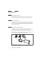


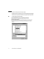

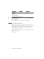
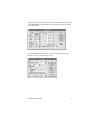
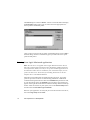
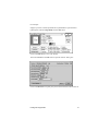


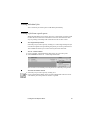
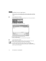
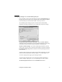
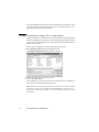


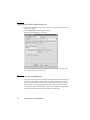
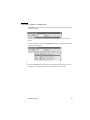
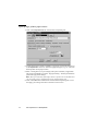
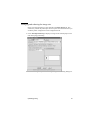
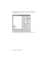
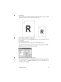
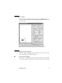
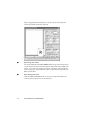
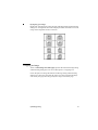
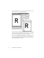
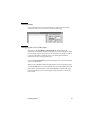


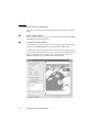
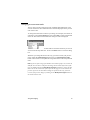
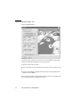
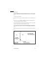
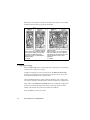
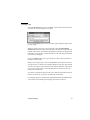
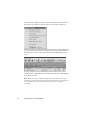
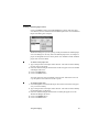


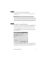
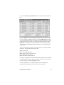
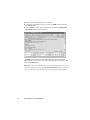
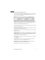
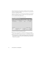
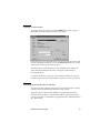
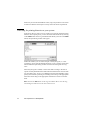
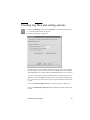
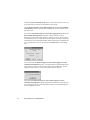

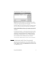
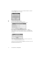
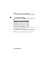
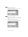
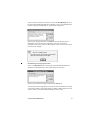
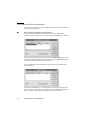
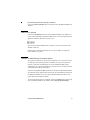
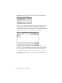

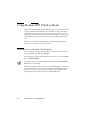
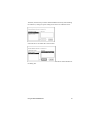
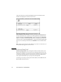
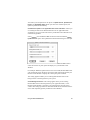
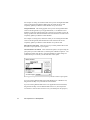
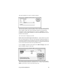
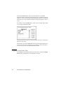
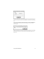
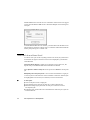
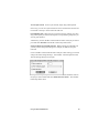


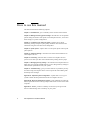


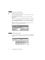
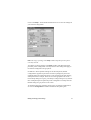
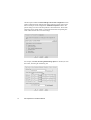

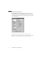


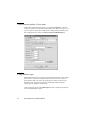

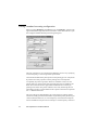
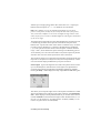


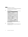
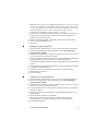
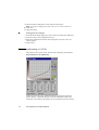
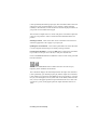

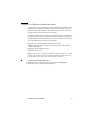
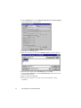
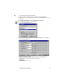

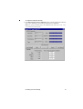
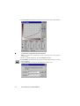
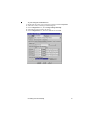
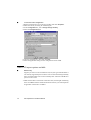
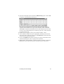
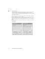
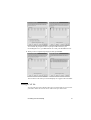

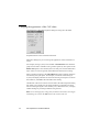

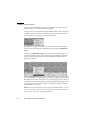
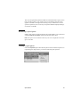
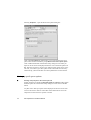

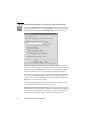


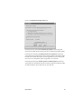


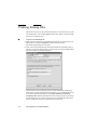

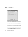

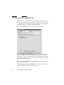
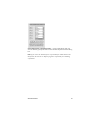
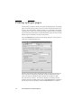
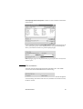

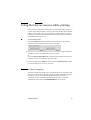
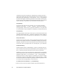

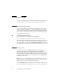


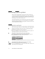
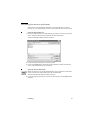
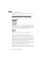
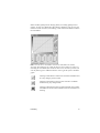
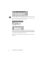
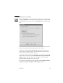


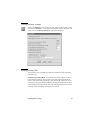
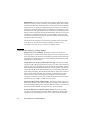


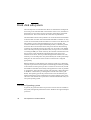
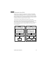
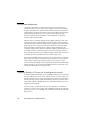


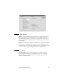


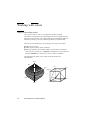

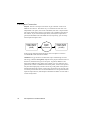


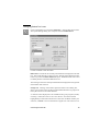


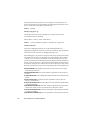
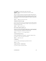
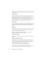

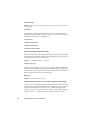


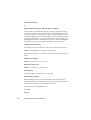


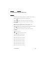
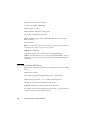


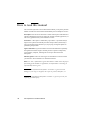


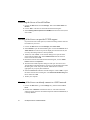


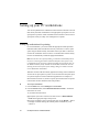
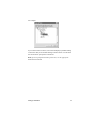
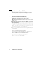

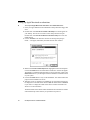
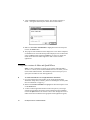
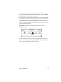


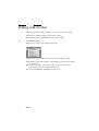
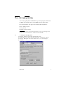
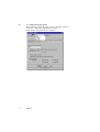
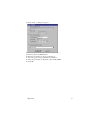


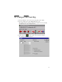
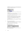


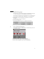
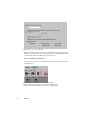


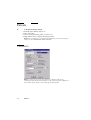
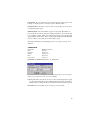
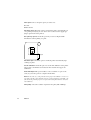
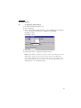
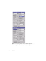

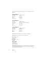
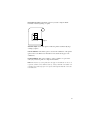
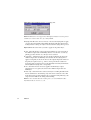


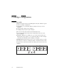
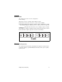


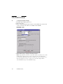
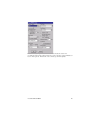
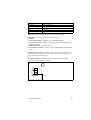
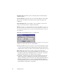


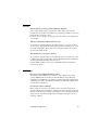

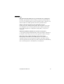


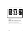
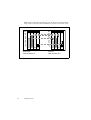


![[TCDView Settings] section](http://vs1.manualzilla.com/store/data/005709836_1-de45231247391792cf649ab0ba1e76b6-150x150.png)