1
1.3 Device Photographs
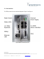
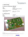
Figure 1: TMIB_AB assembly.
Figure 1 shows a typical TMIB set installation, which consists of two NEMA cards: The
TMIB_AB assembly consisting of TMIB_A featuring TS1 loop contacts and status LEDs as well
as the TMIB_B, which contains the sensor interface connections and the RS485/SDLC bus
connectivity for TS2 cabinets.
PROPRIETARY
The information contained in this document may be subject to change without notice.
The information contained in this document shall remain the sole exclusive property of s.m.s smart microwave sensors GmbH.
TMIB Data Sheet.doc I Page 4 of 15 I January 10, 2014
www.smartmicro.de