1
List of Figures
Figure 1-1: SENtral M&M Module Reference Schematic ......................................................... 4
2
Figure 3-1: I C Timing Diagram ................................................................................................ 9
2
Figure 3-2: I C Slave Write Example ...................................................................................... 11
2
Figure 3-3: I C Slave Read Example, with Repeated START................................................ 11
2
Figure 3-4: I C Slave Write Register Address Only ................................................................ 11
2
Figure 3-5: I C Slave read register from current address ....................................................... 11
Figure 4-1: SENtral Initialization Sequence ............................................................................ 13
Figure 4-2: SENtral Operational States .................................................................................. 13
Figure 4-3: SENtral Normal Operation Flow ........................................................................... 18
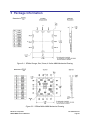
Figure 5-1: SENtral Orange, Red, Green, & Yellow M&M Mechanical Drawing .................... 25
Figure 5-2: SENtral White M&M Mechanical Drawing............................................................ 25
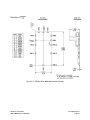
Figure 5-3: SENtral Blue M&M Mechanical Drawing.............................................................. 26
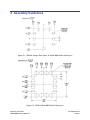
Figure 6-1: SENtral Orange, Red, Green, & Yellow M&M Solder Pad Layout ....................... 27
Figure 6-2: SENtral White M&M Solder Pad Layout .............................................................. 27
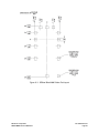
Figure 6-3: SENtral Blue M&M Solder Pad Layout ................................................................ 28
Figure 7-1: SENtral M&M Purple Schematic ........................................................................... 29
Figure 7-2: SENtral M&M Pink Schematic .............................................................................. 30
Figure A2-0-1: Parameter Load Process ................................................................................ 35
Figure A2-0-2: Parameter Retrieve Process .......................................................................... 36
Figure A3-0-1: SENtral Blue M&M Zero-Ohm Resistor Location ........................................... 40
List of Tables
Table 2-1: Performance Characteristics ................................................................................... 6
Table 2-2: Absolute Maximum Ratings .................................................................................... 6
Table 2-3: Operating Conditions............................................................................................... 7
Table 3-1: SENtral M&M Module Pin Assignments .................................................................. 8
2
Table 3-2: I C Timing Parameters .......................................................................................... 10
Table 4-1: Configuration File Upload from EEPROM Registers ............................................ 14
Table 4-2: Registers for Initial Set-up ..................................................................................... 15
Table 4-3: Normal Operation Registers .................................................................................. 17
Table 4-4: Results Registers .................................................................................................. 19
Table 4-5: Standby Registers ................................................................................................. 20
Table 4-6: Pass-Through Registers........................................................................................ 21
Table 4-7: Hardware-Related Error Indications ...................................................................... 22
Table 4-8: Software-Related Error Indications ....................................................................... 23
Table 4-9: ErrorRegister Indications ....................................................................................... 23
Table 4-10: RAMVersion Register Values .............................................................................. 24
Table 7-1 Pressure Senor Data Accesss ................................................................................ 31
Table A2-0-1: Registers Used for Parameter Transfer........................................................... 34
Table A2-0-2: Parameter Numbers ........................................................................................ 37
Table A2-0-3: DriverID & AlgorithmID Definition .................................................................... 39
PNI Sensor Corporation
SENtral M&M Technical Datasheet
Doc #1020129 revG
Page 2