1
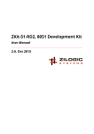
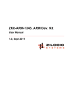
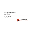
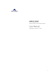
Audio Board
User Manual
1.0, Oct 2013
Audio Board User Manual
Rev. 1.0
This work is licensed under the Creative Commons Attribution-Share Alike 2.5 India License. To
view a copy of this license, visit http://creativecommons.org/licenses/by-sa/2.5/in/ or send a letter
to Creative Commons, 171 Second Street, Suite 300, San Francisco, California, 94105, USA.
Audio Board User Manual
Rev. 1.0
Table of Contents
1. Audio Board ...........................................................................................................................
1. Overview ........................................................................................................................
2. Board Features ..............................................................................................................
3. Locating Components ....................................................................................................
4. Block Diagram ................................................................................................................
5. Power Supply .................................................................................................................
6. SPI Interface ...................................................................................................................
7. Connectors and Headers ...............................................................................................
8. Specifications .................................................................................................................
2. Board Usage ..........................................................................................................................
1. Audio Basics ..................................................................................................................
2. Compression ..................................................................................................................
3. Creating Raw PCM .........................................................................................................
4. Pseudocode Functions ...................................................................................................
5. Playing Raw PCM ...........................................................................................................
6. Using DataFlash for Storage ...........................................................................................
A. Legal Information ..................................................................................................................
1. Copying ..........................................................................................................................
2. Limited Hardware Warranty ...........................................................................................
Zilogic Systems
1
1
1
1
1
2
2
2
3
4
4
5
5
6
6
7
9
9
9
Page iii
Audio Board User Manual
Rev. 1.0
Chapter 1. Audio Board
1. Overview
The Audio Board provides a high speed DAC, with an AF amplifier and speaker, capable of playing
voice and music samples. The Audio Board has as on-board DataFlash for storing audio samples.
The board also provides the capability to control the volume through software, using a digital
potentiometer.
2. Board Features
The Audio Board has the following features
• MCP4801, 8-bit SPI DAC
• AT45DB321D, 4MB DataFlash
• MCP4021, non-volatile digital potentiometer for volume control
• On board speaker
• Headphone jack
• Standard 0.1" FRC header for connection to MCU
• Ready to go with Zilogic motherboards
3. Locating Components
The location of the components on the board is indicated in the following diagram.
Figure 1.1. Front View
4. Block Diagram
The devices available on the board, is shown in the following block diagram. Each device is
described in detail in the following sections.
Zilogic Systems
Page 1
Audio Board User Manual
Rev. 1.0
Figure 1.2. Block Diagram
5. Power Supply
The Audio Board is powered from the motherboard through the VCC on the 10-pin FRC header.
Detailed power supply specifications are available in section Specifications.
6. SPI Interface
The digital audio samples are provided to the DAC through a SPI interface. The DataFlash is also
accessed through the same SPI. The DAC is selected by CS1 . The DataFlash is selected by CS0 .
The volume is controlled through a simple up/down serial interface, by two TTL inputs VOL_CS
and VOL_U/D . The state of the VOL_U/D at the falling edge of VOL_CS determines if increment
or decrement is desired. Subsequent rising edges in VOL_U/D indicates the amount of steps to
increase/decrease.
7. Connectors and Headers
7.1. INPUT Connector
The audio board can be interfaced through the INPUTS SPI bus connector. The signal details are
given below.
Table 1.1. SPI FRC-10 Connector
Pin #
Signal
Description
1
VCC
Power supply
2
SCK
Serial Clock
3
MISO
Serial Output
4
MOSI
Serial Input
5
CS0
Chip Select for DataFlash
6
CS1
Chip Select for DAC
7
FLASH_RST
DataFlash reset
8
VOL_CS
Chip Select for Digital Potentiometer
9
VOL_U/D
Increment/Decrement
10
GND
Ground
Zilogic Systems
Page 2
Audio Board User Manual
Rev. 1.0
8. Specifications
Parameter
Value
Condition
VCC
Voltage
5V
Max. Current
200mA
Digital Inputs
Input Low Voltage
0.0 - 0.8V
Input High Voltage
3.5 - 5.0V
Zilogic Systems
Page 3
Audio Board User Manual
Rev. 1.0
Chapter 2. Board Usage
1. Audio Basics
An audio signal when captured through a microphone is available as a time varying voltage, as
shown in Figure 2.1, “Signal”. When such signals are to be stored in a computer, they have to
digitized. The digitization is a two step process.
1. Sampling
2. Quantization
Figure 2.1. Signal
Sampling. A time varying voltage signal, has infinite no. of values between two time points, say
second 0 and second 1. As such it is impossible to store these values in a computer. Instead we
approximate the signal by looking at the signal periodically, say every 10ms. We note the voltage at
0ms, 10ms, 20ms, 30ms and so on. An example is shown in Figure 2.2, “Sampling and Quantization”.
This way of storing only specific time points of a signal is called Sampling. If the sampling period
is T , 1/T is called the Sampling Frequency.
The only restriction on the sampling frequency, is that, the sampling frequency should be twice the
maximum frequency in the signal, for the signal to be completely reproduced.
Quantization. A time varying voltage signal, that varies between say -3V and 3V, has infinite no.
of values between -3V and 3V. Here again we restrict ourselves to a set of values that are equally
spaced between -3V and 3V. For example, we might choose a spacing of 1V, and hence will store
only -3V, -2V, -1V, 0V, 1V, etc. If at a time point we read a value of 0.8V, then we round if off to 1V, and
store 1V instead. Each of these voltages is given a binary representation, as shown in the following
table. It is this binary representation that actually gets stored.
Voltage
Binary Representation
-3V
001
-2V
010
-1V
011
0V
100
1V
101
2V
110
3V
111
This way of restricting ourselves to a set of values, is called Quantization. The no. of values we
restrict ourselves to determines the accuracy with which the signal has been captured, and the
Zilogic Systems
Page 4
Audio Board User Manual
Rev. 1.0
accuracy with which it can be reproduced. The more the no. of levels more the no. of bits required
to represent each sample. The no. of bits required to represent a sample is called the Bit Depth
or Bits Per Sample.
Figure 2.2. Sampling and Quantization
The following table indicates the sampling frequency and the audio bit depth, for various different
audio quality.
Quality
Sampling Frequency
Bits Per Sample
Telephone
8KHz
8
AM Audio
11.025KHz
8
FM Audio
22.050KHz
16
CD
44.1KHz
16
DVD
48KHz
16
2. Compression
A five minute stereo audio signal stored in CD quality, will occupy about 50 MB. Fortunately, audio
data can easily be compressed. An MP3 or OGG compression will result in just 5 MB of compressed
data. Uncompressed audio is generally called PCM. And when such PCM data is stored in a file
without any headers, it is called a Raw PCM file.
3. Creating Raw PCM
Audio is generally stored in a compressed format like MP3. But these need to be converted to Raw
PCM before it can be sent to the Audio Board. The Audio Board can play audio with the following
parameters:
• Bits Per Sample: 8
Zilogic Systems
Page 5
Audio Board User Manual
Rev. 1.0
• Sampling Frequency: 8kHz
• Channels: 1
A Raw PCM file with these parameters can be created using tools like SOund eXchange (SOX),
FFmpeg, etc.
4. Pseudocode Functions
The pseudocode presented in the following sections, assume the existence of the following
functions:
spi_tx_rx(byte)
Transmits an 8-bit integer byte to the SPI device, and
returns the received byte as an 8-bit integer.
gpio_set_pin(pin,
state)
Sets the state of an GPIO pin to high or low. pin is an integer,
representing the GPIO pin no. state is an integer, 0 for
low and 1 for high. The pin should have previously been
configured to output mode.
udelay(usecs)
Generates a delay.
microseconds.
usecs
specifies
the
delay
in
5. Playing Raw PCM
The Raw PCM audio created using the instruction in Section 3, “Creating Raw PCM” can be stored
in Flash memory of a micro-controller. The micro-controller can then play the audio by sending it
to the DAC through a SPI interface. The following SPI parameters should be configured
• Transmit data on falling edge of the clock. CPOL = 0, CPHA = 0 or CPOL = 1, CPHA = 1.
• Transmit data bytes MSB first.
The following is the pseudocode to play a sample from the 8KHz 8-bit Raw PCM audio.
play_sample(sample):
gpio_set_pin(CS1, 0)
byte = (sample >> 4) & 0x0F ❶
byte |= 0x10 ❷
spi_tx_rx(byte)
byte = (sample << 4) & 0xF0 ❸
spi_tx_rx(byte)
gpio_set_pin(CS1, 1)
❶
❷
❸
First byte contains the upper nibble, of the sample.
Bit 4 indicates when set to 1 indicates Active Mode, and when set to 0 indicates Power Down
mode.
Second byte contains the lower nibble, of the sample.
The following is the pseudocode to play a sequence of samples the 8KHz 8-bit Raw PCM audio. The
sampling period is 125us for 8KHz audio. Hence we send out one sample every 125us.
play(sample_list):
for each sample in sample_list:
play_sample(sample)
Zilogic Systems
Page 6
Audio Board User Manual
Rev. 1.0
udelay(125)
6. Using DataFlash for Storage
As discussed earlier, Raw PCM audio data can easily consume lot of space. The Flash memory in
micro-controllers is generally not sufficient to store such data. The Audio board provides a 4MB
DataFlash for easy storage and retrieval of audio data.
The DataFlash itself is access through the SPI interface. Data is organized in a DataFlash in pages.
Each page is 528 bytes in size.
The pseudocode to read a page from the DataFlash.
read_page(pageno, data):
gpio_set_pin(CS0, 0)
spi_tx_rx(0xD2)
spi_tx_rx((pageno & 0x1FE0) >> 5)
spi_tx_rx((pageno & 0x001F) << 3)
spi_tx_rx(0)
spi_tx_rx(0)
spi_tx_rx(0)
spi_tx_rx(0)
spi_tx_rx(0)
for i in 1 ... 528:
data[i] = spi_tx_rx(0)
gpio_set_pin(CS0, 1)
The pseudocode to write a page to the DataFlash.
wait_ready():
gpio_set_pin(CS0, 0)
spi_tx_rx(0xD7)
ready = (spi_tx_rx(0) & 0x80
while ready == 0:
ready = spi_tx_rx(0) & 0x80
gpio_set_pin(CS0, 1)
write_page(pageno, data):
gpio_set_pin(CS0, 0)
spi_tx_rx(0x82)
spi_tx_rx((pageno & 0x1FE0) >> 5)
spi_tx_rx((pageno & 0x001F) << 3)
spi_tx_rx(0)
for i in 1 ... 528:
spi_tx_rx(data[i])
Zilogic Systems
Page 7
Audio Board User Manual
Rev. 1.0
gpio_set_pin(CS0, 1)
wait_ready()
Zilogic Systems
Page 8
Audio Board User Manual
Rev. 1.0
Appendix A. Legal Information
1. Copying
This work is licensed under the Creative Commons Attribution-Share Alike 2.5 India License. To
view a copy of this license, visit http://creativecommons.org/licenses/by-sa/2.5/in/ or send a letter
to Creative Commons, 171 Second Street, Suite 300, San Francisco, California, 94105, USA.
2. Limited Hardware Warranty
The warranties provided by Zilogic Systems in this Limited Hardware Warranty apply only to
Hardware Products you purchase for your use, and not for resale. The term "Hardware Product"
means a computing device with a specific function and limited configuration ability.
2.1. LIMITED HARDWARE WARRANTY
Zilogic Systems warrants that the hardware components of its Hardware Product shall be free from
material defects in design, materials, and workmanship and will function, under normal use and
circumstances, in accordance with the documentation provided, for a period of one (1) year from
the date of purchase of the Hardware Product.
Your sole and exclusive remedy, and Zilogic Systems' sole and exclusive liability for defective
hardware components, shall be that Zilogic Systems, subject to the terms and conditions of
this Section, and solely upon confirmation of a defect or failure of a hardware component to
perform as warranted, shall at its sole option, either repair or replace the nonconforming hardware
component. All replacement parts furnished to you under this warranty shall be refurbished and
equivalent to new, and shall be warranted as new for the remainder of the original warranty period.
All defective parts, which have been replaced, shall become the property of Zilogic Systems. All
defective parts that have been repaired shall remain your property.
2.2. EXCLUSIONS
The foregoing warranties and remedies shall be void as to any Hardware Products damaged or
rendered unserviceable by one or more of the following: (1) improper or inadequate maintenance
by anyone other than Zilogic Systems or Zilogic Systems' authorized engineers, (2) interfacing
supplied by anyone other than Zilogic Systems, (3) modifications, alterations or additions to the
Hardware Products by personnel not certified by Zilogic Systems or Zilogic Systems' authorized
engineers to perform such acts, or other unauthorized repair, installation or other causes
beyond Zilogic Systems' control, (4) unreasonable refusal to agree with engineering change
notice programs, (5) negligence by any person other than Zilogic Systems or Zilogic Systems'
authorized engineers, (6) misuse, abuse, accident, electrical irregularity, theft, vandalism, fire, water
or other peril, (7) damage caused by containment and/or operation outside the environmental
specifications for the Hardware Products, (8) alteration or connection of the Hardware Products to
other systems, equipment or devices (other than those specifically approved by Zilogic Systems) not
in accordance to the board and on-board device specifications (9) any use that is inconsistent with
the user manual supplied with the Hardware Product. The warranty period is not extended if Zilogic
Systems repairs or replaces a warranted product or any parts. Zilogic Systems may change the
availability of limited hardware warranties, at its discretion, but any changes will not be retroactive.
2.3. HARDWARE RETURN PROCEDURES
If a Hardware Product or one of its component parts does not function as warranted during the
warranty period, and such nonconformance can be verified by Zilogic Systems, Zilogic Systems, at
Zilogic Systems
Page 9
Audio Board User Manual
Rev. 1.0
its election, will provide either return and replacement service or replacement with a refurbished
part/unit for the Hardware Product under the type of warranty service Zilogic Systems designates
for that Hardware Product. A defective Hardware Product or one of its component parts may only
be returned to Zilogic Systems upon Zilogic Systems' prior written approval. Any such approval
shall reference an RMA number issued by an authorized Zilogic Systems service representative. If
you do not register the Hardware Product with Zilogic Systems, you may be required to present
proof of purchase as evidence of your entitlement to warranty service. The Hardware Product’s
serial number will be required for all RMA cases.
Transportation costs, if any, incurred in connection with the return of a defective item to Zilogic
Systems shall be borne by You. Any transportation costs incurred in connection with the redelivery
of a repaired or replacement item to You by Zilogic Systems shall be borne by Zilogic Systems;
provided, however, that if Zilogic Systems determines, in its sole discretion, that the allegedly
defective item is not covered by the terms and conditions of the warranty or that a warranty claim
is made after the warranty period, the cost of the repair by Zilogic Systems, including all shipping
expenses, shall be reimbursed by You.
2.4. HARDWARE REPLACEMENT PROCEDURES
Zilogic Systems will attempt to diagnose and resolve your problem over the phone or e-mail. Upon
determination of the hardware issue is related to a malfunction of one of the Hardware Product
components, an RMA process will be initiated by Zilogic Systems.
For Warranty Replacement service, it is required that you deliver the faulty unit to a location Zilogic
Systems designates, and provide courier name and tracking number to Zilogic Systems. After the
Faulty unit is returned to Zilogic Systems, Zilogic Systems will use commercially reasonable efforts
to ship the replacement hardware within fourteen (14) business days. Actual delivery times may
vary depending on availability of the spares and customer’s location.
2.5. ADDITIONAL RESPONSIBILITIES
You agree:
• To provide Zilogic Systems or its partner with sufficient and safe access to your facilities to
permit Zilogic Systems to fulfill its obligations.
• To ship back the faulty Hardware Product (or replaceable unit) suitably packaged, quoting
the RMA number, to the Zilogic Systems designated location.
• You shall ship the faulty Hardware Product once Zilogic Systems approves the RMA and
provide the courier name and tracking number.
• To securely erase from any Hardware Product you return to Zilogic Systems for any reason
all programs and data not provided by Zilogic Systems with the Hardware Product. You
acknowledge that in order to perform its responsibilities under this Limited Hardware
Warranty, Zilogic Systems may ship all or part of the Hardware Product or its software to
third party locations around the world, and you authorize Zilogic Systems to do so.
2.6. LIMITATION OF LIABILITY
Zilogic Systems' development kits are not designed, authorized or warranted to be suitable for use
in medical, military, aircraft, space or life support equipment, not in applications where failure or
malfunction of a Zilogic Systems product can resonably be expected to result in personal injury,
death or severe property or environmental damage.
NOTWITHSTANDING ANYTHING ELSE IN THIS AGREEMENT OR OTHERWISE, NEITHER ZILOGIC
SYSTEMS NOR ITS SUPPLIERS WILL BE LIABLE WITH RESPECT TO ANY SUBJECT MATTER OF
THIS AGREEMENT UNDER ANY CONTRACT, NEGLIGENCE, STRICT LIABILITY, OR OTHER LEGAL
Zilogic Systems
Page 10
Audio Board User Manual
Rev. 1.0
OR EQUITABLE THEORY, REGARDLESS OF WHETHER ZILOGIC SYSTEMS OR ITS SUPPLIERS WERE
ADVISED OF THE POSSIBILITY OF SUCH DAMAGES, FOR: (i) ANY PUNITIVE, INCIDENTAL OR
CONSEQUENTIAL DAMAGES OR LOST DATA OR LOST PROFITS; OR (ii) FOR COSTS OF PROCUREMENT
OF SUBSTITUTE GOODS, TECHNOLOGY OR SERVICES; OR (iii) FOR ANY CLAIMS BASED ON ANY
ERROR, DEFECT OR NONCONFORMITY IN THE PRODUCTS OR SERVICE, FOR ANY AMOUNT IN
EXCESS OF THE PRICE PAID TO ZILOGIC SYSTEMS FOR SUCH DEFECTIVE PRODUCT(S) OR SERVICE;
OR (IV) FOR ALL OTHER CLAIMS NOT RELATED TO AN ERROR, DEFECT OR NONCONFORMITY IN
THE PRODUCTS, ANY AMOUNTS IN EXCESS IN THE AGGREGATE OF THE AMOUNT PAID TO ZILOGIC
SYSTEMS HEREUNDER DURING THE THREE (3) MONTHS PRECEDING THE DATE THE CAUSE OF
ACTION AROSE.
WARRANTY DISCLAIMER. EXCEPT AS STATED HEREIN, ZILOGIC SYSTEMS MAKES NO WARRANTIES
WITH RESPECT TO any PRODUCT, license or SERVICE AND DISCLAIMS ALL Statutory or IMPLIED
WARRANTIES, INCLUDING WITHOUT LIMITATION WARRANTIES OF MERCHANTABILITY, FITNESS FOR
A PARTICULAR PURPOSE, or arising from a course of dealing or usage of trade and any WARRANTIES
OF NONINFRINGEMENT. ZILOGIC SYSTEMS DOES NOT WARRANT THAT THE ZILOGIC SYSTEMS
PRODUCT(s) WILL MEET any REQUIREMENTS or THAT THE OPERATION OF ZILOGIC SYSTEMS
PRODUCTS WILL BE UNINTERRUPTED OR ERROR FREE.
Zilogic Systems
Page 11