1
4 Installation and Testing
Page 23
4.7.4 Timing Test
BUS
A
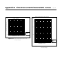
The timing characteristics available by programming the relay
are illustrated in Figures A.1 through A.16. Output trip should
occur as shown for any given TIME DIAL setting, to within 10%
or 20 milliseconds (whichever is greater). Verification of timing
accuracy can be limited to low current levels for convenience.
B
C
Verify timing accuracy as follows:
1.
After performing the “Preliminary Steps’’ (Page 19), connect the input current source to terminals 7 and 8 on the
relay case (Phase A).
2.
Select the time overcurrent characteristic of choice by
entering its identifying code number into the Phase curve
(Pcur) register. (Reference Table 3.) Similarly load the
Ground curve register with the characteristic of choice (if
ground current monitoring is a relay option).
3.
4.
52
Set the PHASE TAP switch to position A. Load 99 into the
Time Dial register. (The Phase tAP calibrate register is still
at the 00 setting given in “Preliminary Steps.’’)
2.0 x TAP, and
b.
5.0 x TAP
Adjust the TIME DIAL to 20 and repeat step 4.
51
7
51
17
C
51
18
51
13
N
51
16
C
51
52
OVERCURRENT RELAY
POWER CIRCUIT BREAKER
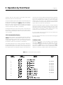
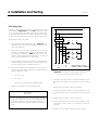
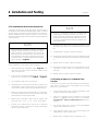
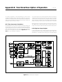
Figure 12. Two-Phase with Residually Connected
Ground, Current Sensing Connections
6.
Disconnect the input current source from terminals 7 and
8 (Phase A) and connect it to terminals 14 and 15 (Phase
B).
7.
Repeat steps 2 through 5 above for Phase B.
8.
Disconnect the input current source from terminals 14 and
15 (Phase B) and connect it to terminals 17 and 18 (Phase
C).
9.
Repeat steps 2 through 5 above for Phase C.
NOTE
If this is a single-phase relay, this concludes a minimal
Timing Test. Other TAP switch positions may be tried
within the limitations of the current source. If this is a
three-phase relay with ground, perform the following
steps.
B
LINE
Check the results against the graphed values.
5.
A
LEGEND
A
Measure the timing from the application of input current to
output contact closure for currents that are adjusted to the
following multiples of TAP:
a.
51
8
10. Disconnect the input current source from terminals 17 and
18 (Phase C) and connect it to terminals 13 and 16
(Ground).
11. Repeat steps 2 through 5 above for ground current.