1
1 General Information
Some applications require that the instantaneous element be
active for phase, but not for ground, and vice versa. Other
applications may require instantaneous tripping with no time
overcurrent function. When the time or instantaneous function
is not desired, this may be achieved by disabling either when
configuring the relay at Display Sequence 20 of the Configuration Menu (see Page 11).
For some applications, the ground element may be present, but
not desired. It may be disabled completely at Display Sequence
20 of the Configuration Menu (see Page 11).
Alternatively, ground trip functions can be shifted to the auxiliary
output relay if this option is installed. This option is configured at
Display Sequence 20 of the Configuration Menu (see Page 11).
1.8 Auxiliary Output Relay (Option 1-2)
This option includes an additional target identified as “INST 2/
CLOSE”. The option can be used in any one of three ways:
a.
b.
c.
INST 2. This provides a second instantaneous trip contact,
which can be set independently of INST 1, and the contact
can be used in a different circuit. This is for application in
reclosing schemes to block reclosing for high magnitude
faults. It can also be used to block tripping of an interrupting
device above its interrupting rating.
COMMAND ACTUATED CLOSE. This selection is only
available if the SCOR relay is equipped with a communications card (Option 2-C). This is used to permit remote
closing of the circuit breaker. A remote close signal may be
transmitted over the communications link to initiate closure
of this output relay if the breaker is open. The relay contact
must be wired into the circuit-breaker close circuit in this
application.
Separate GROUND TRIP. It is necessary in some applications to trip a separate lockout relay for ground faults. This
can be achieved by selecting Option 1-2, and configuring
the relay to cause tripping through this separate relay
contact for ground faults. The ground tripping can be for
operation of both the time and instantaneous elements, but
either can be configured to be disabled if desired.
Page 3
1.9 Communications Option
1.9.1 The Ports
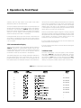
The communications interface (a plug-in board, Option 2-C)
supports an RS-232 port on the front panel and an RS-485 port
on the back of the relay’s case. (These are also known by the
designations EIA-232 and EIA-485.) Both ports have equal
access to the relay’s registers. When connection is made to the
RS-232 port, the RS-485 port is disabled.
The RS-232 port is for relatively short range communication
(under 50 feet). Its intended purposes are for initial configuration,
local testing and maintenance when the relay is not connected
to a Power Monitor unit.
The RS-485 port provides for intercommunication between the
relay and a Siemens Power Monitor unit or a computer running
the Power Monitor PC™ software, WinPM™ power monitoring
and control software, or SIEServe™ software. Communication
is provided over a shielded twisted pair cable at distances of up
to 4000 feet. This feature allows configuration, measurement,
and protection functions to be performed or reviewed from a
remote location.
1.9.2 Communications
The data and configuration capability of the communications
link includes:
Real-time data for amperes (each phase and ground),
and amperes demand (each phase). The monitored current is expressed in primary kiloamperes:
Imonitored = Irelay (CT ratio)
Relay status (normal/timing/tripped), and breaker position (open/closed).
Event record, with amperes prior to trip, time stamp,
element which caused trip, and fault accumulation.
Trip log, including status changes, RMS current, and time
stamp. The last 20 events are stored in the relay’s nonvolatile memory.