1
1 General Information
1.1 Description
The Siemens Communicating Overcurrent Relay (SCOR) is a
microprocessor-based, time overcurrent relay designed for
easy incorporation into a computer-monitored power system.
It is available in a number of styles to supply single-phase, twophase-with-ground, three-phase, and three-phase-with-ground
protection for 60 Hz power systems.
The relay provides for the incorporation of an optional plug-in
communications board to interface with the Siemens Power
MonitorTM display and monitoring unit and the Siemens ACCESS™ system. The communications interface, when fully
implemented, allows remote monitoring of real-time system
and circuit breaker information and the transmission of event
and historical data, as well as remote configuration of operating
parameters.
1.2 Application
The SCOR relay is utility grade and is provided in a draw-out
case with built-in test facilities. It is used for the protection of
medium voltage electrical power systems. It is designed to
monitor the outputs of standard (5 A secondary) current transformers and, when it operates, to close an output contact that
may be used to trip a circuit breaker.
The relay requires control power for its internal circuits. A
number of ac and dc voltage options are available for this
purpose that match the usual ac or dc control power used for
tripping the circuit breaker.
1.3 The Time Overcurrent Function
1.3.1 Pickup
A coarse incremental selection of overcurrent pickup tap is
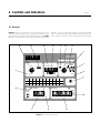
provided by front panel rotary switches. One switch simultaneously sets the pickup tap for all the monitored phases. If
ground is also monitored, a second rotary switch independently
sets the ground overcurrent pickup tap.
A fine incremental adjustment that provides 99 intermediate
pickup points between adjacent positions of the rotary switches
is provided by entering data into the memory of the internal
microcomputer tap calibration registers.
1.3.2 Timing
A time delay is initiated when a pickup point is exceeded. When
the current drops below pickup, the timing circuit is reset
immediately. The amount of delay required before trip is a
function of the overcurrent magnitude.
Page 1
One of 16 families of time overcurrent characteristics may be
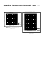
selected for the monitored phases. These families are graphically illustrated in Figures A.1 through A.16 in Appendix A. If
ground current is monitored, its timing characteristic is independently selected from the 16 families.
Selection of the timing characteristics is made at the front panel
or via one of the two communications links. After a characteristic
is selected, it is adjusted to specific requirements by choosing
the TIME DIAL number. (These are the numbers in a vertical row
along the right hand margin of Figures A.1 through A.16.) This
TIME DIAL number (0 to 99) selects one of the 100 characteristic
curves available for each characteristic. (Only 14 of the 100
curves in the relay’s memory are shown on each graph because
of space limitations.)
The selected TIME DIAL number is entered into the relay’s
memory, again using either the front panel data entry controls,
or one of the two communications links. The available characteristic curves include one definite time, six inverse time, and
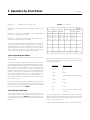
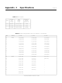
nine I2T curves. (Refer to Table 4..)
1.3.3 Trip and Reset
When the monitored current exceeds the overcurrent pickup
point, the TMG LED illuminates as timing begins. The timing
process continues until the interval calculated by the selected
time overcurrent characteristic is completed (thereby tripping
the associated output contact and target indicators), or until the
sensed overcurrent drops below the pickup setting (which
causes the timer to reset). In either case (trip or reset), the timing
process is terminated. The TMG LED extinguishes at reset, but
remains on at trip as an indication of contact closure.
If a relay output is closed, it is immediately reset when the
monitored current drops below the pickup setting. Targets,
however, remain tripped until manually reset at the front panel.
(Control power is required to reset the targets.)
1.4 RMS Sensing
The SCOR protective relay uses RMS Sensing, a technology
first introduced by Siemens in 1985, to sample the current wave
shape and quickly calculate the effective heating value of the
current. SCOR relays evaluate the impact of harmonics and
provide accurate circuit protection. The SCOR relay uses a sum
of squares algorithm for both determining trip level and for
calculating metered values of the relay current level. The input
waveform is sampled several times to determine instantaneous
values. These instantaneous values are processed to obtain the
true RMS value of the input current.