1
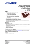
TECHNICAL DATASHEET #TDAX021301
Valve Controller – 6 On/Off
P/N: AX021301
2 Analog and 3 Frequency Command Inputs
6 On/Off Outputs (Option: PWM)
CANopen®
Features:
• 2 user selectable analog inputs
(0-5V, 0-20 mA, 4-20 mA, PWM, Frequency/RPM,
Digital Active High)
• 3 user selectable frequency inputs
(Digital Active High, Digital Active Low, PWM,
Frequency/RPM)
• 6 outputs for hydraulic On/Off valves
• User selectable option for outputs: Pulsed, Timed, PWM
• 12V or 24VDC power (nominal)
• Standard control logic
• 1 CAN (CANopen®), 1 RS-232
• SAE J1939 module available (P/N: AX021300)
• Hardware is available as a platform for application-specific software or setpoints
• User programmable functionality
• .EDS provided to interface to standard CANopen® tools
• Rugged IP67 packaging and connectors
Description:
The controller drives up to 6 on/off valves at 5 Amps over a CANopen® network.
Alternatively, the user can select pulsed, timed or PWM output types. It accepts up to 2 analog inputs (0-5V,
0-20 mA or 4-20 mA) and 3 digital inputs for connection to a variety of analog machine sensors or levers.
The user can also select PWM, Frequency/RPM or 16-bit Counter inputs. Each input can be configured to
measure the input value and send the data to the CAN network using a TPDO. In addition, any output on
the controller could be configured to use any of the inputs as a control signal or an enable instead of taking
the command information from the CAN bus. Standard embedded software is provided. The AX021301 is a
versatile controller compliant with the CiA standard DS-401. It supports many objects from that device profile
as well as some manufacturer objects to provide expanded functionality. All objects are user configurable
using standard commercially available tools that can interact with a CANopen ® Object Dictionary via an
.EDS file. Depending on how they set it up, the user can easily switch from having the output respond to
CAN commands; using the discrete inputs to drive some or all of the outputs; or having them go to an
individually preset state in error mode. Rugged IP67 rated packaging in addition to a 9-36V power supply
input section suits mobile equipment control applications.
Applications:
•
•
Off-highway equipment
Hydraulic systems
Ordering Part Numbers:
CANopen® 6 On/Off Valve Controller: AX021301
EDS File, User Manual: CD-AX021301
Accessories:
PL-DTM06-12SA-12SB Mating Plug Kit
(The KIT is comprised of: DTM06-12S, DTM06-12SB, 2 W12S and 24 contacts.
The Axiomatic stock # is FG-IOCTRL-19.)
BLOCK DIAGRAM
TDAX021301
2
Technical Specifications:
Inputs
Power Supply Input - Nominal
12 or 24VDC nominal (9…36 VDC power supply range)
Surge protection is provided.
Reverse Polarity Protection
Analog Inputs
Provided
2 inputs (Refer to Table 1.0 and Table 2.0)
Inputs are user selectable.
•
Analog (0-5V, 0-20mA or 4-20mA)
•
PWM (up to 5kHz, 0-100% D.C.)
•
Frequency
•
Digital (Active High)
Analog GND connections are provided.
3 inputs (Refer to Table 1.0 and Table 2.0.)
Inputs are user selectable.
•
Digital (Active High or Active Low)
•
PWM (up to 5kHz, 0-100% D.C.)
•
Frequency
A digital GND is provided.
NB. The max. total current draw on the power supply input pins is 7 A @ 24VDC, at one time.
Analog GND
Digital Inputs
Digital GND
Table 1.0 Selection of Inputs to AX021300
Input Type
Description
# of Inputs
There are a total of 5 input channels available, which are user selectable from a variety of input types.
Refer to the user manual for details.
Disable Inputs
Each input can be configured as a disable input command. When disable is selected, no CAN messages
associated with that channel are sent to the network.
Analog Inputs
Up to 2 analog inputs are available.
0…5VDC
4…20mA or 0…20mA
Digital Inputs
Up to 5 active high, digital inputs is user selectable.
Up to 2 active low, digital inputs is user selectable.
Active High - The input is configured to read the state of the input (switch is connected to a +V signal when
ON).
Active Low – The input is configured to read the state of the input (switch is connected to a GND signal
when ON).
PWM Signal Inputs
Up to 5 PWM inputs are available to interface to a PWM signal from an ECM, PLC or other.
PWM Signal Frequency: up to 6kHz
Amplitude: 5-12V
PWM Duty Cycle: 0 to 100%
Pulse Inputs
Up to 5 pulse (Frequency) inputs are available.
TDAX021301
3
Table 2.0 - Absolute Maximums for Inputs
Min
Max
Units
Comments
Power Supply
9
36
V dc
¾
¾
Reverse Polarity and Surge protection is provided.
Software, under and over voltage security features.
Analog Input Voltage
Analog Input Current
PWM Input Frequency
0.05
0
50
36
21
6000
Vdc
mA
Hz
¾
200 =< Freq <= 1000 Hz recommended for better
accuracy
PWM duty cycle Input
Freq/RPM Input Frequency
Digital Input Voltage
0
10
4
100
65000
36
%
Hz
Vdc
Table 3.0 - Input Accuracy
Input Type
0 – 5 VDC
0 (4) – 20 mA
PWM
Frequency / RPM
Accuracy
+/- 1 % of actual input voltage
100 %
+/- 0.1 % duty cycle
+/- 0.15 % of actual input frequency
Outputs
Output Type
Digital Output
Pulsed Output
Timed Output
PWM Output
Overcurrent and Short Circuit
Protection
Output Voltage Regulation
TDAX021301
6 outputs are user selectable from the following.
•
Digital
•
Timed
•
Pulsed
•
PWM
The output response is user selectable from the following.
•
Disabled
•
Normal On/Off
•
Inverted On/Off
•
Latched
There are thirteen setpoints per channel that are associated with the output and how
it is controlled and responds to the control signals.
High Side (sourcing)
Drives up to 6 On/Off Valves (up to 5A each)
The output toggles between OFF and ON states based on the states of the control
logic.
NB. The maximum total current draw permitted on the power supply input pins is 6
Amps @ 24VDC, at one time.
The pulsed output type is controlled by a digital ON-OFF state. However, unlike a
digital output, when a pulsed output logic state is ON, the output will be turned on/off
at the frequency set in object 2230h DO Output Frequency, with the duty cycle set in
object 2231 DO Duty Cycle.
The pulsed output type is controlled by a digital ON-OFF state. However, unlike a
digital output, when a timed output logic state comes ON, the output will be turned
ON after the value in object 2240h DO Start Up Delay has elapsed. The output will
stay ON for the time set in object 2241h DO ON Time, then shut off (even though the
logic state is still ON). If object 2242h DO Timer Repeat is TRUE, then the output will
be OFF for the time set in object 2243h DO OFF Time before coming back ON. The
ON/OFF cycle will continue while the output logic state is still ON.
For this output type, the output will be switched at the frequency in object 2230h DO
Output Frequency. The duty cycle is fixed at minimum 0% and maximum 100%. The
output PWM will be proportional to the input measured. The PWM output is linearly
defined by the input minimum and maximum set in objects 2420h and 2421h.
Provided
93 % of Supply voltage when all 6 outputs are ON (See Figure 1.0.)
4
Output Volt Percentage vs. Number Of Outputs ON
100.00
99.00
98.00
Percentage [%]
97.00
96.00
95.00
94.00
93.00
92.00
91.00
Output Voltage Percentage
1
2
3
4
5
6
99.33
98.17
97.08
95.92
94.92
93.83
Number of Outputs ON
Figure 1.0 - % Output Voltage vs. No. of Outputs ON
General Specifications
Microprocessor
Control Logic
Communications
User Interface
Network Termination
Diagnostics
TDAX021301
DSP56F8346
Standard control logic (Refer to User Manual UMAX021301.)
For application-specific control logic, contact Axiomatic.
1 CAN port (CANopen®)
Compliant with the CiA standard CiA DS-401 V3.0 – CANopen® device profile for
Generic I/O modules (CAN in Automation 2008)
1 RS-232 port
EDS File is provided.
The controller architecture consists of a set of internal functional blocks, which can b
programmed and arbitrarily connected together to achieve the required system func
specific application. All objects are user configurable using standard commercially a
that can interact with a CANopen® Object Dictionary via an .EDS file.
It is necessary to terminate the network with external termination resistors. The
resistors are 120 Ohm, 0.25W minimum, metal film or similar type. They are
placed between CAN_H and CAN_L terminals at both ends of the network.
Current draw from the solenoid(s) is read by the microprocessor
and stored in memory.
5
Electrical Connections
Refer to Table 3.0.
Deutsch DTM series 24 pin receptacle (DTM13-12PA-12PB-R008)
Mating plug: Deutsch DTM06-12SA and DTM06-12SB
with 2 wedgelocks (WM12S) and 24 contacts (1062-20-0122)
that accept 18 AWG wire.
Use dielectric grease on the pins when installing the controller.
Packaging and Dimensions
High Temperature Nylon housing - Deutsch IPD PCB Enclosure (EEC-325X4B)
4.62 x 5.24 x 1.43 inches 117.42 x 133.09 x 36.36 mm
(W x L x H excluding mating plugs)
Weight
Operating Conditions
Protection
0.55 lbs. (0.25 kg)
-40 to 85°C (-40 to 185°F)
IP67, Unit is conformally coated in the housing. Plugs carry an IP69 rating.
TDAX021301
6
Table 3.0 - Typical Connections, AX021301
Grey Connector
Pin # Function
1
Ground 6
2
Ground 5
3
Ground 4
4
Ground 3
5
Ground 2
6
Ground 1
7
Digital Output 1
8
Digital Output 2
9
Digital Output 3
10
Digital Output 4
11
Digital Output 5
12
Digital Output 6
Pin #
1
2
3
4
5
6
7
8
9
10
11
12
Black Connector
Function
BATT +
CAN HI
Serial Communication TXD (Not Used)
Serial Communication RXD (Not Used)
Input 1 (Analog)
Input 2 (Analog)
Ground
Input 5 (Digital)
Input 4 (Digital)
Input 3 (Digital)
CAN LO
BATT -
Note: CANopen® is a registered community trade mark of CAN in Automation e.V.
Specifications are indicative and subject to change. Actual performance will vary depending on the application and
operating conditions. Users should satisfy themselves that the product is suitable for use in the intended application. All
our products carry a limited warranty against defects in material and workmanship. Please refer to our Warranty,
Application Approvals/Limitations and Return Materials Process as described on www.axiomatic.com/service.html.
Form: TDAX021301-07/20/11
TDAX021301
7