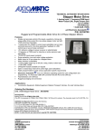
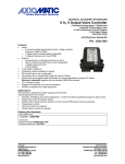
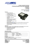
1
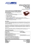
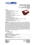
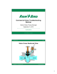
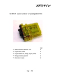
TECHNICAL DATASHEET #TDAX021211 CAN to 10 Output Valve Controller P/N: AX021211 12Vdc, 24Vdc or 48Vdc 10 Outputs Drive Hydraulic Valves CANopen® Features: Command messages are received through the CAN network (no physical inputs) 10 universal outputs of up to 2.5A are user selectable from the following types (up to a maximum of 7A of controller power supply intake at one time). o Output Disabled o Proportional Current o Hotshot Digital o On/Off Digital o Proportional Voltage o PWM Duty Cycle 12Vdc or 24Vdc or 48Vdc nominal input power 1 CAN port (CANopen®) SAE J1939 module available (P/N: AX021210) Hardware is also available as a platform for application-specific software Rugged packaging and connectors CE mark .EDS provided to interface to standard CANopen® tools Description: The controller features 1 CAN port for controlling the outputs and diagnostics over the CAN bus. It accepts a nominal input power supply voltage of 9…60Vdc. Using the CAN network, it can provide control of up to ten outputs, configured for a wide variety of responses and up to 2.5A per channel (max 7A per module). For example, it can drive proportional valves, on/off valves or provide a hotshot control profile. PWM signal or proportional voltage outputs are also user selectable. Standard software is provided. The sophisticated microprocessor can accommodate complex application-specific control algorithms for advanced machine control on request. Rugged packaging and power supply surge protection suits the harsh environment of mobile equipment with on-board battery power. Settings are user configurable via standard CANopen tools. Applications: Off-highway construction equipment Municipal vehicles Ordering Part Numbers: CANopen® Controller: AX021211 EDS File: EDS-AX021211 PC-based CANopen Configuration Tool: Industry standard CANopen PC-based software Accessories: PL-DTM06-12SA-12SB Mating Plug Kit Hardware Block Diagram: TDAX021211 2 Logical Functional Block Diagram: TDAX021211 3 Technical Specifications: Input Power Supply Specifications Power Supply Input - Nominal 12Vdc or 24Vdc or 48Vdc nominal (9…60Vdc) NB. The maximum total current draw permitted on the power supply input pins is 7 Amps @ 24VDC, at one time. Protections Surge and transient protection is provided. Reverse polarity protection is provided. Over-voltage protection is provided. Under-voltage protection is provided. Supply Current 110 mA @ 12Vdc Typical; 60 mA @ 24Vdc Typical; 40 mA @ 48Vdc Typical WARNING: The 10 outputs are user selectable from 0 to 2000 mA but the unit can only handle a maximum of 7A of controller power supply intake at one time. At no time should the total intake current of the controller exceed 7A due to the rating of the connector. Failure to do so will result in unpredictable damage to unit. Input Specifications CAN commands CANopen® Output Specifications Universal Outputs 10 Outputs High side switching (sourcing output up to 2.5A/each), grounded load Current sensing for closed-loop control, current feedback on object 2370h Fully independent, software controlled High Frequency Drive at 25 kHz (fixed for current and hotshot output types) Notes: Load at supply voltage must not draw more than 2.5A. The number of outputs ON at one time is limited by the rating of the Deutsch IPD contacts (pins on the connector). The maximum total current draw permitted on the power supply input pins is 7 Amps @ 24VDC, at one time. Output Type The user can select between the following output types. Output Disabled Proportional Current (0…2.5A) Hotshot Digital (0…2.5A, 0…10000 mSec.) On/Off Digital (0…2.5A) Sourcing from power supply or output off Proportional Voltage (up to supply) PWM Duty Cycle (150Hz…5000Hz, 0 to 100%) Current PID Loop User configurable (Use with caution.) Output Adjustments Digital Current: 0 to 2500 mA Hotshot Hold Time: 0 to 10000 ms Proportional Current: 0 to 2500 mA Proportional Voltage: 0 to 60V PWM Duty Cycle: 0 to 100% PWM Frequency: Three independent output timer banks – each timer bank is shared as follows. Outputs 1-4, outputs 5-8 and outputs 9-10 1 Hz to 25000 Hz (conditions apply – Refer to the User Manual.) Ramp Up: 0 to 60000 ms Ramp Down: 0 to 60000 ms Dither Amplitude: 0 to 400 mA Dither Frequency: Three independent dithers – each dither selection is shared as follows. Outputs 1-4, outputs 5-8, and outputs 9-10 Fully configurable from 50 to 400 Hz Resolution and Accuracy Current Outputs: 1 mA resolution; +/- 2% error Voltage Outputs: 0.1V resolution; +/- 5% error PWM Outputs: 0.1% resolution, +/- 1% error Protection for Output + The unit is fully protected against short circuit to ground. Unit will fail safe in the case of a short circuit condition, self-recovering when the short is removed. Error Detection EMCY code generation (object 1003h) and fault reaction is possible (1029h) when an open or short circuit is detected at the output (current mode only). TDAX021211 4 Output Response Profiles: OUTPUT Maximum Single Slope Dual Slope Either Breakpoint Minimum COMMAND 0 Minimum Breakpoint Maximum Figure 1 – Proportional Output vs. Command Profile ON COMMAND OFF Hotshot Current [mA] OUTPUT Hold Current [mA] 0 [mA] Hotshot Time [ms] TIME Figure 2 –Hotshot Digital Profile General Specifications Microprocessor STM32F205VGT6 16-bit, 1024 kByte flash program memory Compliance CE mark Compliant to the EMC Directive Complaint to the RoHS Directive Vibration MIL-STD-202G, Test 204D and 214A 10.86 Grms (Random) 15 g peak (Sine) TDAX021211 5 Control Logic Standard embedded software. Refer to the User Manual. User programmable functionality using SDO object access, per CiA DS-301 Application-specific software is available on request. An output can be controlled either by an on-board control signal (such the result from a lookup table or a math function) or a CANopen object that has been mapped to an RPDO. By default, analog outputs are setup to respond to the corresponding CANopen RPDO message. By default, analog outputs are configured as proportional current types. Outputs can be configured to respond to any control source found in the list of configurable options in Table 1.0. Table 1.0 - Configurable Control Sources Communications Value Meaning 0 Control Source Not Used (Ignored) 1 CANopen Message (RPDO) 2 Constant Function Block 3 PID Control Function Block 4 Lookup Table Function Block 5 Mathematical Function Block 6 Programmable Logic Function Block 7 Output Commanded Field Value 8 Output Feedback Field Value 9 Power Supply Measured 10 Processor Temperature Measured 1 CAN port (CANopen®) The controller’s object dictionary is compatible with the CiA DS-404 device profile (Device profile for measurement devices and closed-loop controllers). In addition to the standard objects for this device profile, the controller also includes a number of manufacturer specific objects to extend the functionality beyond that of the basic profile. The controller is compliant with the following CAN in Automation (CiA) standards. [DS-301] CiA DS-301 V4.02 – CANopen® Application Layer and Communication Profile. CAN in Automation 2005 [DS-404] CiA DS-404 V1.2 – Device Profile for Measurement Devices and Closed-Loop Controllers. CAN in Automation 2002 [DS-305] CiA DS-305 V2.0 – Layer Setting Service (LSS) and Protocols. CAN in Automation 2006 User Interface .EDS provided to interface to standard CANopen ® tools Diagnostics – CAN Network The controller can detect and flag open and short circuit loads and provides this information to the CAN network. The controller supports a number of EMCY (Emergency Frame Codes) as defined by DS-404 and DS-301 and these include error codes. Refer to the User Manual for details. Baud Rate User configurable as 1 Mbit/s; 800 kbit/s; 500 kbit/s; 250 kbit/s; 125 kbit/s; 50 kbit/s; 20 kbit/s; or 10 kbit/s Network Termination It is necessary to terminate the network with external termination resistors. The resistors are 120 Ohm, 0.25W minimum, metal film or similar type. They should be placed between CAN_H and CAN_L terminals at both ends of the network. TDAX021211 6 Electrical Connections Deutsch DTM series 24 pin receptacle (DTM13-12PA-12PB-R008) Mating plug: Deutsch DTM06-12SA and DTM06-12SB with 2 wedgelocks (WM12S) and 24 contacts (0462-201-20141). 20 AWG wire is recommended for use with contacts 0462-201-20141. Packaging and Dimensions High Temperature Nylon housing - Deutsch IPD PCB Enclosure (EEC-325X4B) 4.62 x 5.24 x 1.43 inches 117.42 x 133.09 x 36.36 mm (W x L x H excluding mating plugs) Operating Conditions -40 to 85C (-40 to 185F) Refer to Table 2.0 for the pin out. Storage Temperature -50 to 105 C (-58 to 221 F) Weight 0.60 lb. (0.27 kg) Protection IP67, Unit is conformal coated in the housing. Mounting Mounting holes sized for ¼ inch or M6 bolts. The bolt length will be determined by the end-user’s mounting plate thickness. The mounting flange of the controller is 0.63 inches (16 mm) thick. If the module is mounted without an enclosure, it should be mounted to reduce the likelihood of moisture entry. The CAN wiring is considered intrinsically safe. The power wires are not considered intrinsically safe and so in hazardous locations, they need to be located in conduit or conduit trays at all times. The module must be mounted in an enclosure in hazardous locations for this purpose. All field wiring should be suitable for the operating temperature range of the module. Install the unit with appropriate space available for servicing and for adequate wire harness access (6 inches or 15 cm) and strain relief (12 inches or 30 cm). TDAX021211 7 Table 2.0 – Pin out: AX021211 Pin # 1 2 3 4 5 6 7 8 9 10 11 12 Grey Connector Function Ground 5 Ground 4 Ground 3 Ground 2 Ground 1 BATT BATT + Output 1 Output 2 Output 3 Output 4 Output 5 Pin # 1 2 3 4 5 6 7 8 9 10 11 12 Black Connector Function Output 6 Output 7 Output 8 Output 9 Output 10 CAN HI CAN LO Ground 10 Ground 9 Ground 8 Ground 7 Ground 6 Notes: CANopen® is a registered community trade mark of CAN in Automation e.V. Specifications are indicative and subject to change. Actual performance will vary depending on the application and operating conditions. Users should satisfy themselves that the product is suitable for use in the intended application. All our products carry a limited warranty against defects in material and workmanship. Please refer to our Warranty, Application Approvals/Limitations and Return Materials Process as described on www.axiomatic.com/service.html. Form: TDAX021211-07/29/15 TDAX021211 8