1
Slide the appliance back until the mounting brackets hit the back face of the stand
arms.
Secure the brackets, fixing through the hole in the back face using 2 No.6 selftapping screws.
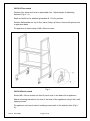
Drill mounting surface (hole diameter 5.0mm) to dimensions shown in Fig 5 and fix
into position using 4 M4 x 20mm screws into rivenuts in the underside of the stand
feet.
Fig 5
OA7909 Wall shelf (Fig 6)
Ensure wall construction is substantial enough to support the weight of the
Salamander grill.
Mark and drill wall for M10 Rawl bolts B. Fix shelf to wall.
Position Salamander on top of wall shelf, lining up the mounting holes A in the top
of the shelf with the pierce nuts in the base of the appliance.
IS 318 ECN 3607
Page 10 of 12