1
blacksky
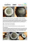
AltAcc2C Instructions
This instruction manual is for the blacksky AltAcc2C an integrating accelerometer and barometric altimeter
data acquisition and recovery system for rocketry.
This package contains:
1.
2.
3.
4.
5.
6.
1 each AltAcc 2C in antistatic bubble bag
Flight Analyzer Windows Software, Version 1.04
RS-232 interface cable
2 ea 10K resistors
Airframe mounting label
This Instruction Manual
In addition, you will need:
1.
2.
3.
4.
Fresh, tested 9V alkaline battery.
Two type 194 automotive lamps or equivalent for testing.
Jewelers screwdriver.
5/32” (4mm) drill bit.
The following items are optional but recommended.
5. Digital Multimeter
6. blacksky HiRMI electric matches
7. blacksky AltAcc Remote Operation Control
8. blacksky AltAcc Palm Adapter
9. blacksky AltAcc Housing
10. blacksky AltAcc Beeper
11. blacksky AltAcc CPR Adapter
12. blacksky E-Jecter Ejection Charge Holder
13. blacksky ARRD Advanced Retention and Release Device
AltAcc QUICK FUNCTION REFERENCE
MAIN ALWAYS TO MAIN, DROGUE ALWAYS TO DROGUE
MODE
ARM AND
LED
Altitude
Display in
feet
Flashes
thousands
then hundreds
NO
NO
§Reset power
§The peak altitude will be
flashed three times
then to standby
Standby
Single Flash
NO
NO
§Self-check OK
§Launch Trigger OFF
§Igniters safe
MAIN Deploy
ARMED
Double Flash
MAIN AT
PEAK
NO
§Launch Trigger ON
§At rest data recorded
MAIN
DROGUE
FUNCTION
DESCRIPTION
DROGUE-toMAIN
Launch
Trigger
Data Transfer
MAIN
ARMED
Triple Flash
ARMED
On Solid in
Flight
NOT ARMED
Single Flash
AT 600,
1200 OR
2400 Feet
YES
NO
DROGUE-
FIRES AT
PEAK
§Launch Trigger ON
§If continuity lost after the
other terminal fires at
peak
§If peak is detected in <6
sec from launch, MAIN
and DROGUE FIRE
YES, (if
selected)
§Launch Trigger by
acceleration detection
of greater than 1 g for .
25 sec
NO
§Data cable between
AltAcc and RS-232 PC
computer port.
§During transfer, LED on
for about 30 sec.
Other Modes
1
Data Storage
Only
ARMED
Double Flash
10K
RESISTOR
NO
§Launch Trigger ON
§At rest data recorded
§No recovery, data only
Backup
Drogue Only
ARMED
Double Flash
10K
RESISTOR
DROGUE
FIRES AT
PEAK
§Launch Trigger ON
§At rest data recorded
§Drogue connected to
Main, fires at peak.
Backup Main
at Low
Altitude
ARMED Triple
Flash
MAIN
FIRES AT
PROGRAM
ALTITUDE
10K
RESISTOR
§Launch Trigger enabled
§At rest data recorded
ALTACC INSTALLATION AND CHECKOUT
THE ALTACC IS RELIABLE ONLY WHEN INSTALLATION AND OPERATION INSTRUCTIONS ARE
FOLLOWED OR CORRECTLY ADAPTED. THE ALTACC MUST BE SECURED TO THE ROCKET
AIRFRAME BE ORIENTED CORRECTLY AND HAVE A KNOWN GOOD BATTERY FOR IT TO WORK
PROPERLY.
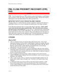
1.1 INSTALLATION – Install the AltAcc with the supplied self-adhesive label. The label is on the outside of the
airframe and the AltAcc mounts behind it inside of the airframe. FIGURE 1 illustrates AltAcc mounting.
1.1.1
Select the mounting location of the AltAcc in your rocket by positioning it on the inside wall of the airframe.
The mounting location must clear the nose cone or coupler and not be exposed to ejection gasses.
1.1.2
Place the AltAcc label on the outside of the airframe at the location selected, and use a center punch or
other sharp instrument and mark the four : label locations: top mount hole; LED; ARM; and lower mount hole.
1.1.3
Drill each marked location with a 5/32” drill, peel off the AltAcc label backing and apply the label over the
drilled holes. Use a sharp hobby knife to trim the holes in the label.
1.1.4
Install the battery, loosen the screw on the battery clip, install a fresh 9V alkaline battery, and tighten the clip
and screw. The LED will flash the last peak altitude; first thousands then hundreds of feet repeat twice then
single flash. Make sure that the red jumper is installed between J1 Pin 1 and Pin 2.
1.1.5
The Main recovery altitude is set at 600 feet, change the altitude with the procedure in Section 3.1.7.
USE CAUTUION WITH THE RECOVERY CHARGES. ALWAYS WEAR EYE PROTECTION WHILE PREPARING,
CONNECTING, AND CHECKING OUT THE RECOVERY SYSTEM.
1.1.6
1.1.7
Prepare and connect your ejection charges. Disarm the AltAcc by turning the ARM screw counterclockwise (DO NOT remove the screw). Loosen the Terminal Block screws (DO NOT remove) and insert the
stripped electric match leads into the Main/Drogue Terminal Block and tighten the screws.
Check the AltAcc recovery Mode by gently tightening the ARM screw, DOUBLE—MAIN ONLY, TRIPLE—
DROGUE to MAIN. DISARM THE AltAcc BEFORE MOUNTING
FIGURE 1 – AltAcc Installation
1.1.8
Mount the AltAcc in the rocket by removing the screws from the standoffs, positioning the AltAcc behind the
top and bottom mount holes and mounting the AltAcc to the inside of rocket with the screws.
1.1.9
ARM the AltAcc ONLY when the rocket is mounted on the launcher, is vertical or can be elevated at a
rate of less than 10 per second. Check the LED flashes to confirm the recovery mode and you are ready to
fly.
1.1.10 Read the Peak Altitude by removing the AltAcc from the rocket and resetting the power by removing and
replacing the red jumper. The last flight recorded will flash out the altitude, first thousands of feet then
hundreds of feet.
1.1.11 Recover the AltAcc data by using the Flight Analyzer software and begin doing real rocket science.
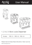
1.2 ALTERNATE INSTALLATION. If desired, the AltAcc can be wired to operate remotely per FIGURE 2. Available
from blacksky is an optional AltAcc 2A Power Panel with Power, ARM, LED and Serial data connector, and
comes with an 18-inch cable.
FIGURE 2. AltAcc 2A Power Panel
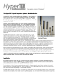
1.3 QUICK ALTACC FUNCTIONAL CHECK is shown in Figure 3 and is used for a quick checkout of the AltAcc. The
test simulates the at-rest, thrust, and coasting flight acceleration. This procedure takes practice to get consistent
results and is simply a functional test of the operation of the AltAcc.
1.3.1 Attach Type 194 bulbs (an automotive type lamp that has wire leads) to the MAIN and DROGUE terminals.
Install the battery, the LED should flash once every two seconds. Tighten the ARM screw and the LED will
flash three times per second.
1.3.2
Hold blacksky AltAcc for at least 15 seconds at a 45-degree angle with the “This End Up” arrows pointing
down. This produces a skewed at rest value to allow flight detection. The skewed value is on the order of –0.7g
relative to the normal orientation.
FIGURE 3. Quick Checkout of the
AltAcc
Quickly rotate the AltAcc 135 degrees (in less than a ¼ second) until it is right side up until the LED goes solid
ON. This motion simulates launch and flight under thrust. The change in acceleration detected is about 1.5g and
represents the rocket under power, enough for Launch Detect.
Quickly rotate the unit 180 degrees (in less ¼ second) until it is upside down to simulate the motor burnout and
coast phases of flight. The acceleration now measured is about –1g relative to the normal orientation.
Hold upside down until the bulbs briefly flash. If done correctly, the Drogue bulb will flash in about 10 seconds
followed immediately by the Main bulb. This happens because the AltAcc detects minimum velocity or peak
altitude, fires the Drogue and then fires the Main because it is below the 600 foot AGL Main deployment altitude.
2
HOW THE ALTACC WORKS
To get the most out of your AltAcc, knowing how it works is important. The operations and functions of the
AltAcc are described as they would occur in set-up and flight. For a quick reference to the AltAcc functions,
see the AltAcc OPERATION QUICK REFERENCE. FIGURE 2 illustrates the key components of the
AltAcc.
FIGURE 2 – Key Components of
the AltAcc
2.1 Power Up -- When a 9V battery is installed, and the jumper is installed between J1 Pins 1 (one) and 2 (two), the
controller boots up and checks each sensor to make sure it's working. If not ARMED, the AltAcc is in standby
mode and flashes the LED once every two seconds. If any error is detected the LED will not flash and the AltAcc
cannot be armed.
2.2 MODE SETTING -- The AltAcc acceleration sensitivity is set with S2 and the recovery mode is set with an electric
match or a resistor connected to the MAIN or DROGUE terminals. See the AltAcc OPERATION QUICK
REFERENCE for a summary of settings.
2.2.1
Acceleration Sensitivity is set with a jumper at S2. The installed jumper provides 25 g sensitivity. Removing
the jumper changes the sensitivity to +50 g’s.
THERE IS A PERMANENT 50K OHM SHUNT ACROSS THE MAIN AND DROGUE TERMINALS FOR EMATCH SAFETY.
2.2.2
Main -- When an Ejection Charge is connected to the MAIN terminals and the ARM SWITCH is tightened,
continuity is sensed across the MAIN terminals and deployment is set for MAIN firing. The LED will flash twice
every two seconds.
THE MAIN IS ALWAYS CONNECTED TO THE MAIN, DROGUE IS ALWAYS CONNECTED TO THE
DROGUE TERMINALS.
2.2.3
Drogue/Main -- When an Ejection Charge is connected to both the DROGUE and MAIN terminals, and the
ARM SWITCH is tightened continuity is sensed across both terminals and sets deployment for MAIN and
DROGUE. The LED will flash three times per second. If only the DROGUE is connected, the LED flashes
once every two seconds and the AltAcc will not arm.
2.2.4
Data Acquisition Only -- The AltAcc may be used for data acquisition only by connecting a 10k ohm
resistor across the MAIN terminals and tightening the ARM SWITCH. This sets the AltAcc for data
acquisition by providing the MAIN sense circuit with continuity.
WHEN EJECTION CHARGES ARE CONNECTED AND THE ALTACC IS ARMED, AVOID ABRUPT
MOTIONS. ARM THE ALTACC ONLY WHEN THE ROCKET IS IN POSITION TO LAUNCH.
2.3 ALTACC FLIGHT -- AltAcc Flight begin when the charges are attached and the AltAcc is ARMED. ARM checks
continuity, set recovery mode and starts AltAcc at-rest data acquisition and waits for the Launch Trigger. When
launch is detected, the AltAcc is Triggered, data is stored and processed in real-time for recovery actions.
At Rest Acceleration and Altitude -- When the AltAcc is installed in the rocket and armed on the launch pad,
the Accelerometer and Pressure sensor data is continuously stored in controller memory to get the at-rest
2.3.1
sensor values.
2.3.2
Launch Trigger -- When the rocket is launched and 1 g of acceleration (relative to the at-rest values) is
sensed for 0.25 seconds, the AltAcc switches to Flight. Data is now stored in non-volatile memory for 4.25
minutes. During this time, the LED remains ON, and goes out at 4.25 minutes.
2.3.3
Peak Detection – After Launch Trigger, the positive acceleration values (during motor burn) and negative
acceleration values (coast) are integrated (added) to detect minimum velocity. When the integrated value
reaches zero the rocket is at minimum velocity and the MAIN or DROGUE deployment system is fired.
IF PEAK IS DETECTED <6 SECONDS FROM LAUNCH TRIGGER, BOTH CHARGES WILL FIRE.
2.3.4
Post Peak Low Altitude Deployment -- After firing at peak, pressure sensor data is compared to the at rest
pressure data during the descent. When the set recovery altitude is detected, the Main is fired. The default
setting for low altitude deployment is approximately 600 feet. Other altitudes, 1200 and 2400 feet can be
selected for MAIN parachute deployment.
2.4 COMMUNICATION – AltAcc communicates through a serial cable from the AltAcc to a DB9 connector
connected to the RS232 serial port of a Personal Computer (PC) or, by using the Palm Adapter to connect to a
palm top computer with the Palm OS.
2.4.1
Flight Analyzer software runs in Windows . Included is the DOS based DataPro or Palm DataPro software.
Section 3 provides details for these applications.
2.4.2
Terminal Commands may be used with the AltAcc and a terminal emulation program. These commands
are case sensitive.
/B – Babble mode streams the data to the terminal.
/R – Sends contents of EEPROM to the terminal.
/CC – Clears the EEPROM.
/L – Sets the Main Deployment altitude to 600 feet.
/M – Sets the Main Deployment altitude to 1200 feet.
/H – Sets the Main Deployment altitude to 2400 feet.
7
POST FLIGHT DATA RECOVERY AND ANALYSIS
ALTACC CALIBRATION IS NOT NECESSARY PRIOR TO FLIGHT. CALIBRATION IS USED FOR
DATA REDUCTION ONLY AND DOES NOT CHANGE FLIGHT PERFORMANCE.
AltAcc data capture and analysis is done using the supplied software used with Flight Analyzer for
Windows , DataPro for DOS, or DataPro for PalmOS
7.1 USING FLIGHT ANALYZER is used with Windows 95 or higher and is loaded into a Personal Computer. Flight
Analyzer software provided with the AltAcc allows data transfer and graphical display of your AltAcc Data for real
rocket science.
7.1.1
Install the Flight Analyzer into your computer.
Insert Disk 1 into the 3.5” drive of your computer.
From ÿ Start button, select Run, enter a:\setup.exe, click OK.
Follow InstallShield instructions displayed to install Flight Analyzer and Disk 2. Installshield will automatically
create a directory in Programs called blacksky that contains Flight Analyzer.
3.1.1
Open the Flight Analyzer from the ÿ Start button, select Programs, then blacksky, then
Flight Analyzer will open and reveal the following display (NOTE, wallpaper graphic not shown for
clarity):
File contains the dropdown file save and load menu.
Save Data File…saves the currently loaded data file
Load Data File…loads a saved file
Load Calibration File…loads a saved Calibration File
Load Parameter File…loads a saved Parameter File
Change Directory…changes the directory path
Printer Setup…sets up your printer
Edit contains drop down edit routine for flight log.
Comm allows you to capture data and configure the data port
Configure Port…the utility for changing the serial port
Capture Data…downloads data from the AltAcc
Calibrate AltAcc …creates an AltAcc calibration file
Clear Data Buffer…clears the AltAcc memory
Live Data…downloads live data from the AltAcc
Main Deploy…allow setting of Main Deployment altitude
Graph opens a table to customize the graphical display when a data file is open.
Help opens a description of the FlightAnalyzer
Opens a saved flight data file.
Sets the length of the graphically displayed data file
Downloads data from your AltAcc
Starts the graphical display of a loaded flight file
Begins display of live data from AltAcc
(Needs the correct Cal File to work properly)
Begins calibration routine for the AltAcc
Main Deployment altitude setting for the AltAcc
3.1.2
Quick Use of Flight Analyzer
§Connect the AltAcc serial cable between a RS-232 port on your computer and the AltAcc; install a 9V battery
(watch polarity); Power Jumper installed; the AltAcc is NOT ARMED.
§Start Flight Analyzer and from the Menu select Comm, set your serial port (typically COM1 or COM2) and click
OK.
Click on this button and the Save Captured Data box will appear, Type in your file name. Make your file name
something that you can remember, such as Pro38-Flight-1. Click on Start and the Communications Status box
will show “Transferring Data” and data transfer percentage.
§
When the data transfer is complete, the Selected Data File box displays the “Summary of Flight box”.
Clicking Print to print, OK to accept or Cancel to reject.
If you accepted the data, click on this button and a graph will appear showing the Velocity, Acceleration and Pressure
Altitude.
§The Value and Timing can be displayed by placing the cursor on the curve of interest, and left clicking. Index lines
will appear on the curve that may be moved right to left using the keys. Shifting from one curve to the next is
done with the ▲▼ keys. Numbers are displayed in the upper left corner are the data value (altitude, velocity or
acceleration) and time from launch.
§Zooming in on an area is done by placing the cursor in the graph area, holding down the left button and dragging
the box to the area of interest.
2.1.1
Downloading the Second Flight
Repeat 3.2.3 to download the second flight. Be sure to name the file before clickingStart.
2.1.2
Adjusting Graph Parameters
The normal Graph display provides Speed, Acceleration and Pressure Altitude. It is possible to customize the
graph to display the data in other units, such as miles per hour, Mach or SI units.
Click on Graph to display a table containing the controls for the graphical display. Changing the title of each
graph is done in the Title column. Changing the Formula changes the units displayed. Normally, the units are
displayed in English units, with Channel 1 being the Acceleration and Channel 2 being altitude in feet.
EXAMPLE: to display acceleration in Meters per second per second, edit Title to read Acceleration
(Meters/sec-sec) and the Formula for Channel 1 becomes Ch1*9.8.
2.1.1
Look at Stored Files in the Flight Analyzer
Click on this button and select a saved flight file from the list and the Selected data file box displays the
Summary of Flight information box.
2.1.2
Calibrate Flight Analyzer for your AltAcc There is a default calibration program loaded in the Flight
Analyzer. However, to get the best possible data reduction, run the Flight Analyzer Calibration Program for
your AltAcc and use this program for displaying your data.
§Connect the AltAcc serial cable between a RS-232 port on your computer and the AltAcc; install a 9V battery
(watch polarity); Power Jumper installed; the AltAcc is NOT ARMED.
Click on this icon and a display will come up that shows a table with the calibration information.
§Enter your altitude and the barometric pressure (check your weather channel or call your airport for the pressure).
Click on this icon to begin barometric calibration.
Minus One Gee Average Hold the AltAcc upside down and click on the icon (hold the AltAcc as still as
possible until data is sampled, about 45 seconds.
Zero Gee Average Lay the AltAcc flat (on its battery holder) and click on the icon, data sampling takes about
45 seconds.
Plus One Gee Average Hold the AltAcc right-side up and click on the icon (hold the AltAcc as still as
possible until data is sampled, about 45 seconds
§Click on OK and a Save As box will appear, name the calibration file using the AltAcc serial number and click on
Save.
§When analyzing data, go to File and Load Calibration File to open the file display of the calibration files. Select
the calibration file for the AltAcc data to be analyzed and click on Open. Subsequent Flight Data File loaded
will use this calibration file for analysis.
§When analyzing data, go to File and Load Calibration File to open the file display of the calibration files. Select
the calibration file for the AltAcc data to be analyzed and click on Open. Subsequent Flight Data File loaded
will use this calibration file for analysis.
§Load your Data File and the new calibration file will be used.
2.1.3 Set Main Deployment Altitude
§Connect the AltAcc serial cable between a RS-232 port on your computer and the AltAcc; install a 9V battery
(watch polarity); Power Jumper installed; the AltAcc is NOT ARMED.
Select this Icon to bring down the Main Altitude Deployment altitude menu.
Click on the altitude desired and the value will be loaded into EEPROM. The battery may be removed and
the altitude will remain set until changed.
2.2 ProRead using the Palm OS
Instead of taking your laptop to the field, AltAcc flight data can be displayed and saved on most of the Palm OS
hand held computers. Many flights can be stored on you Palm for later download to Flight Analyzer. All that is
required is your AltAcc, the blacksky Palm Adapter (a X-modem gender changer) and your Palm.
2.2.1 Load the Palm Software To use the ProRead software, you must load it into the Palm.
Open your Palm Desktop and click on Install.
Click on Add and direct to C: / Program Files / Flight Analyzer / Proread.prc.
Highlight Proread.prc and click on Open .
Click on Done and the next time you Hot Synch, the Proread program will load into your Palm.
6.1.1
Use the Palm to Download and Display AltAcc Data The Palm can download and display AltAcc data. The
data displayed uses the default Cal program loaded in Proread.prc.
Connect the AltAcc serial cable to the Palm Adapter gender changer and the Palm Serial Cable; install a 9V
battery (watch polarity); Power Jumper installed; the AltAcc is NOT ARMED..
Open the ProRead program from the PalmOS Main Menu.
Tap on Read and the AltAcc data will down load to your Palm.
When the download is complete, name your Flight Data File.
To display data, highlight the Flight Data File you wish to display and tap on Info , the data will be displayed with
the default Cal file.
The second flight can be downloaded from the AltAcc with the Read button, be sure to select a different name
for this file.
12.1.1 Down Load Data to Flight Analyzer
Open Flight Analyzer on your PC.
Connect your Palm to the COM port and open Palm ProRead.
On the Palm, tap on Send.
Download data into Flight Analyzer per 3.1.3.
You may now display the flight data using Flight Analyzer.
17.1 PRODATA for DOS-- The prodata software suite runs in DOS and allows you to look at the AltAcc Flight data in
detail and create your own analysis tools. Prodata includes the following executable programs:
proread.exe -- Reads the AltAcc data and creates a data file.
proclear.exe -- Clears the AltAcc memory.
probate.exe – Makes calibration file (prodata.cal) for the AltAcc .
produce.exe -- Reduces AltAcc data to flight performance data.
In addition to the four executable files are the following data files:
prodata.nit -- Default values for the PC RS-232 serial communications port, calibration file and user output
preferences.
prodata.cal -- This file is created by probate.exe and contains calibration reference values for the sensors.
17.1.1 Installation of prodata -- You must install prodata onto your hard drive.
§Make a directory labeled "prodata" on your hard drive.
§Insert the Disk 2 prodata diskette into the 3.5" floppy drive.
§Copy the contents of the prodata file to the prodata directory.
17.1.2 Using the RS-232 Serial Port and DOS -- For proper serial port operation, proread, proclear and probate
must be run in native DOS only. If using Windows, you must exit and restart in Windows and run from the C:
prompt.
17.1.3 AltAcc Calibration AltAcc sensor calibration data is acquired with the probate program. Probate creates a file
called prodata.cal or a user selected name. The prodata.cal file is required for data reduction. The calibration
does not effect the flight performance of the AltAcc as the data is used only with the produce program to
reduce flight data.
17.1.4 AltAcc Clearing Clearing the blacksky AltAcc with proclear between flights assures that old data will not be
read and interpreted causing flight data errors. It is not necessary if using the blacksky AltAcc for recovery
only.
17.1.5 AltAcc Reading Reading data from the AltAcc uses the proread. It is necessary to name each proread file to
allow it to be reduced. The name of each file is described as (eight characters).dat.
17.1.6 AltAcc Data Reduction: The AltAcc is processed using the produce routine. The data is reduced from a file
named when the AltAcc data was read with proread. Following are descriptions of the commands and how to
use the AltAcc data files.
Usage: produce [-cFILE] [-fFILE] [-oFILE] [-nFILE] [-zVAL] [-gVAL] -a -q -h FILE where:
-F FMT
-c FILE
-> Calibration File produced by Probate
-f FILE
-> AltAcc data file produced by proread
-n FILE
-> Override default init file prodata.nit with FILE
-o FILE
-> Output file for produce results
-z VAL
-> One Gee Value (Overrides Cal File One Gee )
-g VAL
-> Gain Override ( Overrides Cal File Gain Factor )
-> if FMT = c or C or x or X then print comma separated values ( ala an Xcel csf file ) Otherwise print
a table of data with headers ( default )
-a
-> Force all the data out, even after touchdown
-b
-> be quiet about it
-h
-> help ( this list )
FILE
-> FILE == AltAcc data file produced by proread
Examples of produce data reduction operations are shown below.
a)
To simply reduce the flight data through minimum velocity deployment with prodata.cal, type:
produce [S] yourname.dat [ENTER]
b)
To reduce the flight data through minimum velocity deployment with prodata.cal and store the reduced data,
type:
produce [S] -o [S] yourname.flt [S] yourname.dat [ENTER].
c)
To reduce the flight data through minimum velocity deployment with a different .cal file and store the reduced
data, type:
produce [S] -c [S] yourname.cal [S] -o [S] yourname.flt [S] yourname.dat [ENTER]
d)
To reduce the flight data through minimum velocity deployment and generate an EXCEL or Lotus type
comma separated variable (.csv) file to be exported to a spreadsheet program for graphical display, type:
produce [S] -F [S] C [S] -o [S] yourname.csv [S]Yourname.dat{ENTER]
e)
To reduce the entire flight data set and generate an EXCEL or Lotus type comma separated variable (.csv)
file to be exported to a spreadsheet program for graphical display, type:
produce [S] -F [S] C [S] -o [S] yourname.csv [S] -a [S]yourname.dat [ENTER]
e)
If option -o was used, the named file (yourname.flt) can be displayed by using the DOS editor, word
processor or a word processor program or scrolled through by typing:
type [S] yourname.flt [S] | more [ENTER]
AltAcc Warranty, Terms and Conditions
Reasonable care has been exercised in the design, fabrication and testing of the AltAcc by blacksky, its
employees, vendors and subcontractors. Blacksky warrants the AltAcc for a period of 90 days from the
date of purchase. Blacksky will repair or replace any AltAcc at its discretion during the warranty period.
Damage to the AltAcc resulting from rocket flight or recovery failures is not warranted under any
circumstances. AltAcc recovery modes are used for experimental purposes only and shall not be used
where failure would cause injury or property damage. The purchaser and user of the AltAcc accepts all
risks and responsibilities for its testing, installation and use. The AltAcc purchaser or user shall not hold
blacksky Corporation, its employees, vendors and contractors liable for any consequential or incidental
damages resulting from its use. First time use of the AltAcc signifies acceptance of these terms. Any
modifications made to the AltAcc by the user or connection of equipment not provided or manufactured
by blacksky Corporation shall make this warranty void
For service or comments contact:
blacksky Corporation
3179 Roosevelt St.
Carlsbad,
CA 92008
760 730-3701
Fax 730-3704
You may also reach us on the web at:
www.blacksky.com
AltAcc2C Specifications
PARAMETER
1.
Recovery Modes
METRIC (subject to change without notice)
Main only with inertial acceleration integration to detect minimum velocity,
equivalent to peak altitude.
Drogue with inertial acceleration integration to peak followed by programmable
Main at user selected barometric low altitudes.
3.Flight Safety Features
The AltAcc will not arm if continuity is not detected across the Main or Drogue
and Main terminals.
A 50K ohm shunt is across the Main and Drogue terminals.
If peak altitude is detected within 6 seconds, both Drogue and Main outputs will
be fired.
If continuity on either Drogue to Main opens in flight, the other output will be
fired at peak.
5.Altitude Display
Status LED flashes peak barometric altitude in thousands and
hundreds of feet to 16K feet (metric values must be converted).
6.Low Altitude Recovery
Programmable 600, 1200, and 2400 200/-0 feet (180, 360, and
720 +60/-0 meters).
7.Mach Sensitivity
Insensitive to Mach+ velocities during ascent.
8.Acceleration Measurement Range
+ 25 g’s and + 50 g’s. Acceleration can exceed set point without
damage, however, some data will be lost..
9.Acceleration Resolution
0.25 + 0.05 g and 0.5 + 0.1 g
10.Lift-Off Detection
1.0 g for 0.25 seconds
11.Velocity Timing Error at Peak
Altitude Detect
+ 2 seconds based on acceleration integration. The peak
detected is the inertial minimum velocity.
12.Maximum Time of Flight to
Deployment
Limited to 4.25 minutes. At altitudes >100,000 feet (>30,000
meters) rocket instability will cause acceleration integration
errors occur.
13.Maximum Velocity to Peak
No theoretical maximum velocity within the data limits.
14.Pressure Range
2.8 to 14.7 PSI (20 to 105 kPa)
15.Pressure Resolution
0.05 + 0.01 PSI (0.40+ 0.1 kPa)
16.Pressure Altitude
Range/Relative Accuracy
0 to 15K is + 105 feet (0 to 4570 + 30 meters)
15.1 to 30K is + 420 feet (4610 to 9140 + 120 meters)
> 30.1K data may not be valid.
4.Data Digitization
8 bit A-to-D converter.
5.Digital Filter
8 sensor samples captured and averaged in 0.062 seconds
6.Data Storage Rate
16 averaged samples per second for each sensor.
7.Flight Storage Time
4.25 minutes
8.Output Type
RS-232 on 7-pin 0.1” spacing connector.
9.Cable Description
3-pin header, 4ft cable to DB9M serial port connector.
10.Input Voltage Range
+7 to +14 Volts (if 9V battery not used.)
11.Standby Current
<5mA average current.
12.Preflight Current
<5mA average current.
13.Igniter Continuity Current
<0.5ma @ 9V (with 9V battery installed)
14.Main/Drogue Output
0.1 sec, > 1.5 A @ 8.5 V (with fresh 9V alkaline battery),
15.Temperature Range
32 TO 158 F (0 to 70 C)
16.Dimensions
1.1” Wide x 3.5” Long x 1.5” High (30. x 91 x 38mm)
17.Weight without battery
1.3 oz (37gms)
18.Weight with battery
<2.8 oz (78gms) (9v alkaline)
19.Battery Holder
9V holder mounted on backside of board.
20.Arming Switch
Screw-down, mounted on front of board.
21.Status LED
Daylight visible LED mounted on front of board.
22.Output Terminals
Dual, two pole 3.5mm terminal blocks, 24 to 18 ga wire.
23.Mounting Screws
6-32 stainless steel, phillips pan head, typical 3/8” long