1
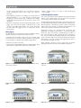
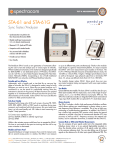
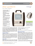
CNT-90 Timer/Counter/Analyzer • 250k measurements/s to internal memory, 750k stored measurements results • Fast GPIB/USB bus speed, 5k meas/s – block mode • Resolution: 12 digits/s (freq.), 100 ps (time), 0.001° (phase) • 14 digits display • Frequency range: 400 MHz as standard. 3, 8, 15 and 20 GHz optional • Ease-of-use: Multi-parameter display and graphical presentation of results • Outstanding performance/ price ratio The Pendulum CNT-90 timer/counter/analyzer is an ultimate tool for measurement, analysis and calibration of Frequency, Time Interval or Phase. The CNT-90 is a high-performance counter with a fast measurement speed to 250,000 measurements/s, and time interval measurement resolution to 100 ps. The CNT-90 offers ease-of-use including graphical display and improved display and improved control over measurement at an outstanding price. Leading Performance The basic performance of the CNT-90 is leading compared to competition: • The • With 5k measurement results transferred per second (block mode) • • • • via GPIB/USB, the CNT-90 can save you up to 90% testing time (and thus money) in test systems by increased throughput. High resolution is vital for R&D and production testing. CNT-90 meets this requirement with 100 ps single shot (time) or 12 digits/s (frequency). Obtained values are displayed with up to 14 digits. Modulation Domain Analysis is performed by capturing fast frequency changes with up to 250k Samples/s. For calibration purposes, the CNT-90 offers very high accuracy through stable internal OCXO time base, low systematic time interval A-B error and high resolution. Wide frequency range to 20 GHz covers most CW and burst microwave frequency measurement needs. There’s no need to invest in a separate microwave counter. Outstanding Performance/Price Ratio The high performance CNT-90 timer/counter/analyzer outperforms all counters on the market (except Pendulum CNT-91), independent of measurement task. • • • graphic presentation of results – histogram, trend line, numerical statistics, modulation domain – provide a clearer understanding of random signal distribution and measurement changes over time – from slow drift to fast jitter, and modulation. Both USB and GPIB interfaces are standard. With USB you won’t need to invest in a GPIB interface card for your PC. The GPIB operates in either SCPI/GPIB or 53131/53132 emulation mode, for plug-and-play replacement in existing ATE systems. Wide frequency range – to 20 GHz – offers microwave CW frequency measurements and very short burst measurements down to 40 ns. Menu-oriented settings reduce the risk of mistakes. Valuable signal information, given in multi-parameter displays, removes the need for other instruments like DVM’s and Scopes. Additional Technical Features CNT-90 does not only offer high-performance, it is an ultimate tool for more specialized measurement. Some great features of the CNT-90 are: • Zero dead-time technique and continuous time-stamping of trigger events. This feature allows correct measurements of Allan Deviation and is very valuable in mechanical (e.g. rotational ctracomco .spe . . . quality Q ... IS O 9001 . UK | 6A Beechwood | Chineham Park | Basingstoke, Hants, RG24 8WA | +44 (0)1256 303630 | [email protected] .. FRANCE | 3 Avenue du Canada | 91974 Les Ulis, Cedex | +33 (0)1 64 53 39 80 | [email protected] om . . . . . rp.c USA | 1565 Jefferson Road, Suite 460 | Rochester, NY 14623 | +1.585.321.5800 | [email protected] CNT-90 • • encoder testing) and medical (e.g. nerve impulse/respiratory cycles) measurements where every single cycle must be measured. Limit qualifying a handy tool for making correct calculation of statistical parameters e.g. to verify the jitter of digital pulses that appear in discrete clusters (e.g. in CD-players or in HDB3coded data). By setting limits you can isolate one cluster in the calculation. Hysteresis compensation in Time Interval measurements reduces trigger level error from the typical 15-20 mV found in most counters on the market today, down to typ. 2.5 mV. This means 6-8 times improved trigger precision in critical time interval measurements. • Battery backup acting as a built in UPS (Uninterrupted Power Supply) Excellent Graphical Presentation One of the great features of the CNT-90 is the graphical display and the menu oriented settings. The non-expert can easily make correct settings without risking costly mistakes. The multi-parameter display with auxiliary measurement values such as Vmax/Vmin/Vp-p in frequency measurements, and frequency/ attenuation/phase, eliminates the need for extra test instruments and provides direct answers to frequently asked questions, like “What is the attenuation and phase shift of this filter?” In stand-by mode the battery pack can keep an OCXO warm and running for over 24 hours. Battery operation of a frequency counter/analyzer is valuable in three different applications: Measurement values are presented both numerically and graphically. The graphical presentation of results (histograms, trends etc.) gives a much better understanding of the nature of jitter. It also provides you with a much better view of changes vs time, from slow drift to fast modulation (trend plot). Three statistical views of the same data set can be viewed: Numerical, Histogram and Trend. It is very easy to capture and toggle between views of the same data (see figure 4, 5 & 6). • Mains-free operation in the field • Transportation of high-stability OCXO to maintain stability, which When adjusting a frequency source to given limits, the graphic display gives fast and accurate visual calibration guidance. Battery Option The CNT-90 has an optional battery pack with 90 Wh capacity, capable of mains-free operation for at least 4.5 hours. gives instant use at destination without any warm-up time Figure 1: Display showing phase value, frequency, attenuation Va/Vb, and auxiliary parameters. Figure 4: Display showing different statistical parameters viewed at the same time. Figure 2: Measure function selection menu, shown with measured results. Figure 5: Display showing the trend (signal over time) of sampled data. Figure 3: Input parameter setting menu shown with measured result. Figure 6: The same result as in Figure 5, now displayed as a histogram. Technical Specifications: CNT-90 All measurements are displayed with a large main parameter value and smaller auxiliary parameter values (with less resolution). Some measurements are only available as auxiliary parameters. Frequency A, B, C Range: Input A, B: 0.002 Hz to 400 MHz Input C (option): Up to 3, 8, 15 or 20 GHz Resolution: 12 digits in 1s measuring time (normal) Aux. Parameter (A, B): Vmax, Vmin, Vp-p Frequency Burst A, B, C (opt. 14/14B) Frequency and PRF of repetitive burst signals can be measured without external control signal and with selectable start arming delay. Functions: Frequency in burst (in Hz); PRF (in Hz) Range: Input A, B, C: See Frequency spec. Minimum Burst Duration: Down to 40 ns Minimum Pulses in Burst: Input A or B: 3 (6 above 160 MHz) Input C: 3 x prescaler factor PRF Range: 0.5 Hz to 1MHz Start Delay: 10 ns to 2sec., 10 ns resolution Aux. Parameter: PRF Period A, B, C Mode: Single, Average Range: Input A, B: 2.5 ns to 1000 sec. (single, average) Input C (option): 10 ns down to 330, 125, 70 or 50 ps Resolution: 100 ps (single); 12 digits/s (avg) Aux. Parameter (A, B): Vmax, Vmin, Vp-p Ratio A/B, B/A, C/A, C/B Range: (10-9) to 1011 Input Frequency: Input A, B: 0.1 Hz to 400 MHz Input C (option): Up to 3, 8, 15 or 20 GHz Aux Parameters: Freq 1, Freq 2 Time Interval A to B, B to A, A to A, B to B Range: Normal Calculation: 0ns to +10 sec. Smart Calculation: -106 sec. to +106 sec. Resolution: 100 ps Min. Pulse Width: 1.6 ns Smart Calculation: Smart Time Interval to determine sign (A before B or A after B) 6 Positive and Negative Pulse Width A, B Range: 2.3 ns to 106 sec. Min. Pulse Width: 2.3 ns Aux. Parameters: Vmax,Vmin, Vp-p Rise and Fall Time A, B Range: 1.5 ns to 106 sec. Trigger Levels: 10% and 90% of signal Vp-p Min. Pulse Width: 1.6 ns Aux. Parameters: Slew rate, Vmax, Vmin Positive and Negative Duty Factor A, B Range: 0.000001 to 0.999999 Freq. Range: 0.1 Hz to 300 MHz Aux. parameters: Period, pulse width Phase A Relative B, B Relative A Range: -180° to +360° Resolution: Single-cycle: 0.001° to 10 kHz, decreasing to 1° >10 MHz. Resolution can be improved via averaging (statistics) Freq. Range: up to 160 MHz Aux. Parameters: Freq (A), Va/Vb (in dB) Vmax, Vmin, Vp-p A, B Range: -50 V to +50 V, -5V to +5V Range is limited by the specification for max input voltage without damage (see input A, B) Freq. Range: DC, 1Hz to 300 MHz Mode: Vmax, Vmin, Vp-p Resolution: 2.5 mV Uncertainty (5V range, typical): DC, 1Hz to 1kHz: 1% +15 mV 1kHz to 20 MHz: 3% +15 mV 20 to 100 MHz: 10% +15 mV 100 to 300 MHz: 30% +15 mV Aux parameters: Vmin, Vmax, Vp-p Time stamping A, B, C Raw time stamp data together with pulse counts on inputs A, B or C, accessible via GPIB or USB only. Max Sample Speed: See GPIB specifications Max Frequency: 160 MHz Timestamp Resolution: 70 ps Input and Output Specifications Inputs A and B Frequency Range: DC-Coupled: DC to 400 MHz AC-Coupled: 10 Hz to 400 MHz Impedance: 1M // 20 pF or 50 (VSWR 2:1) Trigger Slope: Positive or negative Max. Channel Timing Difference: 500 ps Sensitivity: DC-200 MHz: 15 mVrms 200-300 MHz: 25 mVrms 300-400 MHz: 35 mVrms Attenuation: x1, x10 Dynamic Range (x1): 30 mV p-p to 10 V p-p within ±5V window Trigger Level: Read-Out on display Resolution: 3mV Uncertainty (x1): ±(15 mV + 1% of trigger level) AUTO Trigger Level: Trigger level is automatically set to 50% point of input signal (10% and 90% for Rise/Fall Time) AUTO Hysteresis: Freq. range: 1Hz to 300 MHz Time: Min hysteresis window (hysteresis compensation) Frequency: One third of input signal amplitude Analog LP Filter: Nominal 100kHz, RC-type. Digital LP Filter: 1Hz to 50 MHz cut-off frequency Max Voltage Without Damage: 1M: 350 V (DC + AC pk) to 440 Hz, falling to 12 Vrms at 1MHz. 50 : 12 Vrms Connector: BNC Input C (Option 10) Operating Input Voltage Range opt. 10: 100 to 300 MHz: 20 mVrms (-21 dBm) to 12 Vrms 0.3 to 2.5 GHz: 10 mVrms (-27 dBm) to 12 Vrms 2.5 to 2.7 GHz: 20 mVrms (-21 dBm) to 12 Vrms 2.7 to 3.0 GHz: 40 mVrms (-15 dBm) to 12 Vrms Prescaler Factor: 16 Impedance: 50 nominal, VSWR <2.5:1 Max Voltage without Damage: 12 Vrms, pin-diode protected Connector: Type N Female Input C (Option 13) Operating Input Voltage Range: 100 to 200 MHz: 100 mVrms to 7Vrms (typ.) 200 to 300 MHz: 40 mVrms to 7Vrms (typ.) 300 to 500 MHz: 20 mVrms to 7Vrms 0.5 to 3.0 GHz: 10 mVrms to 7Vrms 3.0 to 4.5 GHz: 20 mVrms to 7Vrms 4.5 to 6.0 GHz: 40 mVrms to 7Vrms 6.0 to 8 GHz: 80 mVrms to 7Vrms Prescaler Factor: 256 Impedance: 50 nominal, VSWR <2.5:1 Max Voltage Without Damage: 7Vrms Connector: Type N Female Input C (Option 14 and 14B) Freq. Range: 0.25 to 15 GHz (opt. 14) 0.25 to 20 GHz (opt. 14B) Operating input voltage range: 250 to 500 MHz: -21 to +27 dBm 0.5 to 15 GHz: -27 to +27 dBm 15 to 18 GHz: -27 to +27 dBm (Option 14B only) 18 to 20 GHz: -21 to +27 dBm (Option 14B only) Prescaler Factor: 128 Typical sensitivity option 14B 0 -5 -10 -15 -20 dBm Measuring Functions -25 -30 -35 -40 -45 -50 0 5 10 15 20 25 GHz Typical Spec Impedance: 50 nominal, VSWR <2.0:1 AM tolerance: > 90% within sensitivity range Max Voltage Without Damage: +27 dBm Connector: Type precision N Female Rear Panel Inputs and Outputs Reference Input: 1, 5, or 10 MHz; 0.1 to 5Vrms sine; impedance 1k Reference Output: 10 MHz; >1Vrms sine into 50 Arming Input: Arming of all measuring functions Impedance: Approx. 1k Freq. Range: DC to 80 MHz Rear Panel Measurement Inputs: A, B, C (opt. 11/90) Impedance: 1M//50 pF or 50 (VSWR 2:1) Connectors: SMA female for rear input C, BNC for all other inputs/outputs Auxiliary Functions Trigger Hold-Off Time Delay Range: 20 ns to 2sec., 10 ns resolution External Start and Stop Arming Modes: Start, Stop, Start and Stop Arming Input Channels: A, B or E-rear panel Max Rep. Rate for Arming Signal: Channel A,B: 160 MHz Channel E: 80 MHz Start Time Delay Range: Technical Specifications: CNT-90 20 ns to 2sec., 10 ns resolution Statistics Functions: Maximum, Minimum, Mean, maxMin, Standard Deviation and Allan Deviation Display: Numeric, histograms or trend plots Sample Size: 2 to 2 x 10⁹ samples Limit Qualifier: OFF or Capture values above/below/inside or outside limits Measurement Pacing: Pacing Time Range: 4µs to 500 sec. Mathematics Functions: (K*X+L)/M and (K/X+L)/M. X is current reading and K, L and M are constants; set via keyboard or as frozen reference value (X0) Other Functions Measuring Time: 20 ns to 1000 sec. for Frequency, Burst, and Period Average. Single cycle for other measuring functions Timebase Reference: Internal, External or Automatic Display Hold: Freezes result, until a new measurement is initiated via Restart Limit Alarm: Graphical indication on front panel and/or SRQ via GPIB Limit Values: Lower limit, Upper limit Settings: OFF or Alarm if value is above/below/ inside or outside limits On Alarm: STOP or CONTINUE Display: Numeric + Graphic Stored Instrument Set-ups: 20 instrument setups can be saved/recalled from internal non-volatile memory. 10 can be user protected. Result Storage: Up to 8 measurements of max 32k samples can be stored in local memory for later downloading. Display: Backlit LCD Graphics screen for menu control, numerical read-out and status information Number of Digits: 14 digits in numerical mode Resolution: 320*97 pixels GPIB Interface Compatibility: IEEE 488.2-1987, SCPI 1999, 53131A/53132A compatibility mode Interface Functions: SH1, AH1, T6, L4, SR1, RL1, DC1, DT1, E2 Max. Measurement Rate: GPIB: 5k readings/s (block mode) 500 readings/s (individual GET trig’ed) To Internal Memory: 250k readings/s Internal Memory Size: Up to 750k readings. USB Version: 2.0 Full speed (11 Mbits/s) Bench handling Transit drop test: Heavy-duty transport case and soft carrying case tested according to MIL-PRF-28800F Reliability: MTBF 30,000 hours (calculated) Safety: EN 61010-1, pollution degree 2, meas cat I, CSA C22.2 No 1010-1, CE EMC: EN 61326 (1997); A1 (1998), increased test levels according to EN 50082-2, Group 1, Class B, CE Calibration Power Requirements USB Interface Mode: Closed case, electronic calibration, menu controlled Cal. Frequencies: 0.1, 1, 5, 10, 1.544 and 2.048 MHz Option 23/90 Battery Unit Battery Type: LiIon, 90 Wh External DC input: 10 to 18 V dc; max 6A Operating temp. range: 0 to 40°C Storage: -20 to +60°C, 1 month -20 to +45°C, 3 months -20 to +20°C, 1 year Battery operating time (at 25°C): ON: >4.5 hours Stand-by: >24 hours Charging: Automatically when AC or ext DC is connected Battery status indicator: On-screen with low battery warning Weight: 2.3 kgs General Specifications Environmental Data Class: MIL-PRF-28800F, Class 3 Operating Temp: 0°C to +50°C Storage Temp: -40°C to +71°C Humidity: 5%-95% (10°C to 30°C) 5%-75% (30°C to 40°C) 5%-45% (40°C to 50°C) Altitude: 4,600 meters Vibration: Random and sinusoidal according to MIL-PRF-28800F, Class 3 Shock: Half-sine 30G per MIL-PRF-28800F; Option model STD 19/90 30/90 40/90 Time base type: Standard OCXO OCXO OCXO - Aging per 24h per month per year - Temperature variations: 0˚C to 50˚C 20˚C to 26˚C (typ. values) n/a <5x10⁻⁷ <5x10⁻⁶ <1x10⁻⁵ <3x10⁻⁶ <5x10⁻⁹( 1) <6x10⁻⁸ <2x10⁻⁷ <5x10⁻⁸ <2x10⁻⁸ <5x10⁻¹⁰( 1) <1x10⁻⁸ <5x10⁻⁸ <5x10⁻⁹ <1x10⁻⁹ <3x10⁻¹⁰( 1) <3x10⁻⁹ <1.5x10⁻⁸ <2.5x10⁻⁹ <4x10⁻¹⁰ Short-term stability: =1s (root Allan Variance) =10 s not specified <1x10 <1x10⁻¹⁰ <1x10 <1x10-11 <5x10 <5x10-12 Uncertainty due to: -10 -11 -12 Power-on stability: - Deviation vs. final value after 24 h on time, after a warm-up time of: n/a 30 min <1x10⁻⁷ 30 min <1x10⁻⁸ 10 min <5x10⁻⁹ 10 min Typical total uncertainty, for operating temperature 20˚C to 26˚C, at 2(95%) confidence interval: - 1 year after calibration - 2 years after calibration <7x10⁻⁶ <1.2x10⁻⁵ <2.4x10⁻⁷ <4.6x10⁻⁷ <0.6x10⁻⁷ <1.2x10⁻⁷ <1.8x10⁻⁸ <3.5x10⁻⁸ www.spectracomcorp.com Dimensions and Weight Width x Height x Depth: 210 x 90 x 395 mm (8.25 x 3.6 x 15.6 in) Weight: Net 2.7 kg (5.8 lb), Shipping app. 3.5 kg (app. 7.5 lb) Ordering Information Basic Model CNT-90: 400 MHz, 100 ps Timer/Counter including Standard Time Base Included with Instrument: 3 years product warranty1, line cord, user documentation on CD, and Certificate of Calibration 1 The warranty period may be dependent on country. Input Frequency Options Option 10: 3 GHz Input C Option 13: 8 GHz Input C Option 14: 15 GHz Input C Option 14B: 20 GHz Input C Oscillator Options Option 19/90: Medium Stability Oven Time Base; 0.06 ppm/month Option 30/90: Very High Stability Oven Time Base; 0.01 ppm/month Option 40/90: Ultra High Stability Oven Time Base; 0.003 ppm/month Optional Accessories Option 11/90: Rear Panel Inputs (replaces front panel inputs) Time Base Options (1) After 1 month of continuous operation Max. configuration: 90 to 265 Vrms, 45 to 440 Hz, <40 W, <60 W if battery option Option 22/90: Rack-Mount Kit Option 23/90: Battery Unit Option 27: Carrying Case - soft Option 27H: Heavy-duty Hard Transport Case Option 29/90: TimeView Modulation domain Analysis SW for CNT-90 Option 90/01: Calibration Certificate with Protocol; Standard oscillator Option 90/06: Calibration Certificate with Protocol; Oven oscillator Option 90/00: Calibration Certificate with Protocol; Hold-over frequency aging/week Option 95/05: Extended warranty from 3 to 5 years OM-90: Users Manual English (printed) PM-90: Programmers Manual English (printed) SM-90: Service Manual English GS-90-EN: Getting Started English GS-90-FR: Getting Started French GS-90-DE: Getting Started German February 4, 2013 - 4031 600 90101 rev. 27 Specifications subject to change or improvement without notice. Spectracom is a business of the Orolia Group. ©2010-2013 Orolia USA, Inc.