1
STA-61
makes STA-61 future proof, buy your new sync tester/analyzer
today and expand it with more input modules when you need it.
Packet Sync Measurement
STA-61 allows to measure synchronization conformance simultaneously at a packet sync level (based on SyncE and IEEE1588v2
technologies) and at a traditional physical sync level (1PPS, E1, interface) behind a packet synchronized device. Multiple packet sync
measurements can be performed, whether it’s related to IEEE1588
v2 slave / boundary clock performance qualification or network
Packet Delay Variation (PDV) characterization, SyncE wander can
be also measured at any node in the network.
Examples of Measurement Screens
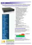
Multiple Signals with Multiple MTIE Masks: Here the MTIE
of the two master and the two slave clock outputs are measured.
The bottom solid lines are the master clocks, the top solid lines are
the slave clocks. The dashed lines are color coded selected masks.
The master clocks are well below all masks, and the slave clocks
with the offset are above all masks, due to high frequency offset.
Raw PDV: Raw PDV can be displayed either as PDV(t), showing
the evolution of PDV depending on daytime, or as distribution.
Forward and Reverse PDV measurements are available.
STA-61 works as an active probe, meaning it acts in the network as
a PTP slave, which can be associated to any visible PTP master in
the network, allowing a precise forward and reverse packet delay
measurement.
Always Accurate
The STA-61 includes a built-in high performance Rubidium oscillator
which allows making sync measurements in places where no accurate frequency/time reference is available. This is key to field commissioning or trouble-shooting operations. In addition, the STA-61G
has a built-in high sensitivity GPS receiver which slaves the internal
reference to provide a few tens of nanoseconds absolute UTC time
accuracy as well as sub10-11 frequency accuracy. No external calibration, and no calibration down-time, is needed with the STA-61G.
Common Mode or Differential Wander Measurements
You can compare all your signals under test to the integrated stable
Rubidium atomic clock, or to an external high-stability standard, to
show the absolute phase variations of all signals under test relative
to the common reference clock. You can also define one of the input
signals as the reference for all other input signals (differential TIE). This
enables for example comparisons of outgoing vs. incoming sync clock
in Network elements, and comparisons between a Grandmaster PTP
and one or several PTP-slaves. For in-depth analysis, you can also read
out cursor data and perform statistical analysis of your measurement.
Sync Probe Mode
The STA-61 can be used as a sync probe when connected to an
IP network for a virtually infinite measurement duration. Thanks to
the WanderView™ for STA-61 free companion software, powerful
and user-friendly functions like remote control, data acquisition,
post-processing, graph display, and report generation are available on a remote PC.
Remote Operation
Remote operation of the STA-61 can be facilitated in many ways.
The STA-61 has a built-in web server including a VNC server. That
means you could monitor and control the STA-61 via Ethernet in a
standard VNC client anywhere in the world, running in a PC, or
even in a smart phone. You can view the screen and the current
measurement progress, and you can control the measurement by
clicking the on-screen controls in the remote VNC client. You can
also connect to the PC program WanderView™ for STA-61 via Ethernet. From WanderView™ you have full control of the STA-61
including continuous data streaming of measurement data, report
generation and advanced post-processing and analysis.
Time & Frequency GPS/Rubidium Reference
STA-61 embeds a high performance time and frequency reference, which benefits from Spectracom know-how in terms of atomic clocks and high performance time-base disciplining. It provides
1PPS, 10 MHz and E1/T1 reference outputs for test cases where
a wander free clock must be provided to the device under test.
Floor Packet Count Display: Floor Packet metrics allow to
characterize network ability to support frequency transfer through
on IEEE1588, according to G.8261.1. The following graph shows
Floor Packet Percentage.