1
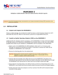
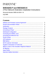
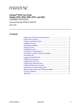
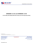
AµD8000-12, AµD8000-12B, and AµD8000Q-12B 12-Port ADSL Micro DSLAMs Installation Instructions Document Number AUD8-A2-GZ40-00 May 2005 Contents Software and Firmware License Agreement ...................................................... 2 Product Documentation Online .......................................................................... 3 Unpacking and Inspecting the Equipment ......................................................... 3 Selecting the Installation Site ............................................................................. 4 Powering Up the AµD8000 ................................................................................ 5 Connecting the SHDSL Line(s) .......................................................................... 5 Loop Bonded SHDSL Connection ..................................................................... 6 SHDSL Parameters ........................................................................................... 6 Connecting the Uplink Interface Line(s) ............................................................. 7 10/100 Ethernet Uplink ...................................................................................... 7 T1 Uplink ............................................................................................................ 8 E1 Uplink ........................................................................................................... 9 Default Settings ................................................................................................. 10 Initial Configuration ............................................................................................ 12 Configuration Using the Command Line Interface (CLI) .................................... 12 Configuration Using the Network Management System (NMS) ......................... 15 RAM and NVRAM .............................................................................................. 18 Local Files .......................................................................................................... 19 LED Indications .................................................................................................. 19 Connector Pin Assignments .............................................................................. 22 Important Safety Instructions ............................................................................. 24 Regulatory Compliance for Class A Equipment ................................................. 25 Warranty, Sales, Service, and Training Information ........................................... 26 AUD8-A2-GZ40-00 May 2005 1 Software and Firmware License Agreement ONCE YOU HAVE READ THIS LICENSE AGREEMENT AND AGREE TO ITS TERMS, YOU MAY USE THE SOFTWARE AND/OR FIRMWARE INCORPORATED INTO THE PARADYNE PRODUCT. BY USING THE PARADYNE PRODUCT YOU SHOW YOUR ACCEPTANCE OF THE TERMS OF THIS LICENSE AGREEMENT. IN THE EVENT THAT YOU DO NOT AGREE WITH ANY OF THE TERMS OF THIS LICENSE AGREEMENT, PROMPTLY RETURN THE UNUSED PRODUCT IN ITS ORIGINAL PACKAGING AND YOUR SALES RECEIPT OR INVOICE TO THE LOCATION WHERE YOU OBTAINED THE PARADYNE PRODUCT OR THE LOCATION FROM WHICH IT WAS SHIPPED TO YOU, AS APPLICABLE, AND YOU WILL RECEIVE A REFUND OR CREDIT FOR THE PARADYNE PRODUCT PURCHASED BY YOU. The terms and conditions of this License Agreement (the “Agreement”) will apply to the software and/or firmware (individually or collectively the “Software”) incorporated into the Paradyne product (the “Product”) purchased by you and any derivatives obtained from the Software, including any copy of either. If you have executed a separate written agreement covering the Software supplied to you under this purchase, such separate written agreement shall govern. Paradyne Corporation (“Paradyne”) grants to you, and you (“Licensee”) agree to accept a personal, non-transferable, non-exclusive, right (without the right to sublicense) to use the Software, solely as it is intended and solely as incorporated in the Product purchased from Paradyne or its authorized distributor or reseller under the following terms and conditions: 1. Ownership: The Software is the sole property of Paradyne and/or its licensors. The Licensee acquires no title, right or interest in the Software other than the license granted under this Agreement. 2. Licensee shall not use the Software in any country other than the country in which the Product was rightfully purchased except upon prior written notice to Paradyne and an agreement in writing to additional terms. 3. The Licensee shall not reverse engineer, decompile or disassemble the Software in whole or in part. 4. The Licensee shall not copy the Software except for a single archival copy. 5. Except for the Product warranty contained in the manual, the Software is provided “AS IS” and in its present state and condition and Paradyne makes no other warranty whatsoever with respect to the Product purchased by you. THIS AGREEMENT EXPRESSLY EXCLUDES ALL OTHER WARRANTIES, WHETHER EXPRESS OR IMPLIED, OR ORAL OR WRITTEN, INCLUDING WITHOUT LIMITATION: a. Any warranty that the Software is error-free, will operate uninterrupted in your operating environment, or is compatible with any equipment or software configurations; and b. ANY AND ALL IMPLIED WARRANTIES, INCLUDING WITHOUT LIMITATION IMPLIED WARRANTIES OF MERCHANTABILITY, FITNESS FOR A PARTICULAR PURPOSE AND NON-INFRINGEMENT. Some states or other jurisdictions do not allow the exclusion of implied warranties on limitations on how long an implied warranty lasts, so the above limitations may not apply to you. This warranty gives you specific legal rights, 2 May 2005 AUD8-A2-GZ40-00 and you may also have other rights which vary from one state or jurisdiction to another. 6. In no event will Paradyne be liable to Licensee for any consequential, incidental, punitive or special damages, including any lost profits or lost savings, loss of business information or business interruption or other pecuniary loss arising out of the use or inability to use the Software, whether based on contract, tort, warranty or other legal or equitable grounds, even if Paradyne has been advised of the possibility of such damages, or for any claim by any third party. 7. The rights granted under this Agreement may not be assigned, sublicensed or otherwise transferred by the Licensee to any third party without the prior written consent of Paradyne. 8. This Agreement and the license granted under this Agreement shall be terminated in the event of breach by the Licensee of any provisions of this Agreement. 9. Upon such termination, the Licensee shall refrain from any further use of the Software and destroy the original and all copies of the Software in the possession of Licensee together with all documentation and related materials. 10. This Agreement shall be governed by the laws of the State of Florida, without regard to its provisions concerning conflicts of laws. Product Documentation Online Complete documentation for Paradyne products is available at www.paradyne.com. Select Support → Technical Manuals. To order a paper copy of a Paradyne document, or to speak with a sales representative, please call 1-727-530-2000. Unpacking and Inspecting the Equipment HANDLING PRECAUTIONS FOR ! STATIC-SENSITIVE DEVICES This product is designed to protect sensitive components from damage due to electrostatic discharge (ESD) during normal operation. When performing installation procedures, however, take proper static control precautions to prevent damage to equipment. If you are not sure of the proper static control precautions, contact your nearest sales or service representative. AUD8-A2-GZ40-00 May 2005 3 Unpack and inspect the equipment. The following components should be included: 1 AµD8000 4 Rubber Bumpers 1 DB9 Socket to RJ45 Plug Adapter If there is visible damage, do not attempt to connect the device. Contact your sales representative. Figure 1. AµD8000-12 ADSL Micro DSLAM Selecting the Installation Site CAUTION: The maximum recommended ambient temperature for the AµD8000 is 65° C (149° F). Do not stack AµD8000 chassis on top of one another; the air vents on top of the chassis require a minimum of 0.5-inch (1.3 cm) free airspace for adequate circulation. Affix the (4) provided rubber bumpers to the bottom corners of the unit to provide surface grip. Tabletop Place the AµD8000 such that the cables will not become a tripping hazard or pull loose from the unit. Rack AµD8000 micro DSLAMs may be placed side by side horizontally on a standard 19" shelf. Ensure all cables are secured such that they will not become a tripping hazard or pull loose from the unit. Remote Cabinet AµD8000 micro DSLAMs may be placed side by side horizontally within the cabinet. Vertical door mount brackets are available for purchase as separate accessories; contact your sales representative for further information. 4 May 2005 AUD8-A2-GZ40-00 Powering Up the AµD8000 Attach DC power leads and a ground connection to one of the two terminal blocks on the back of the AµD8000. Either terminal block may be used. Although not required for operational purposes, both terminal blocks may be connected for redundancy. To apply power to the AµD8000: Procedure 1. Loosen the screws on top of the terminal block 2. Insert the leads and ground wire into the front of the terminal block. Be sure to attach the positive lead to the positive terminal (+) and the negative lead to the negative terminal (–) as indicated on the terminal block labels. 3. Tighten the screws. 4. Turn on the power source and verify that the Power LED on the front of the unit is illuminated. Solid amber illumination indicates one power terminal is connected, and solid green illumination indicates both power terminals are connected. Connecting the SHDSL Line(s) G.SHDSL is the default line code for the AµD8000, and the default bandwidth is 272 kbps. If desired, these settings may be changed once the AµD8000 has been installed and initial configurations have been completed. To connect the SHDSL lines: Procedure 1. Plug your DSL cable’s RJ21 connector into the corresponding RJ21 port on the back of the AµD8000. For most applications, an AµD8000 SHDSL link requires a straight-through DSL cable. The AµD8000 can be connected with a remote subscriber unit via either a single DSL line or double DSL lines (loop bonding). 2. For each port being connected to a remote subscriber unit, verify that the SHDSL link has been established. The SDSL Connection LED for that port will pulse green to indicate the connection has been made. Link up time can vary from one to five minutes depending on the quality, gauge and distance of the copper cables. AUD8-A2-GZ40-00 May 2005 5 Loop Bonded SHDSL Connection CAUTION: Configure identically any ports on the AµD8000 intended for a loop bonded connection prior to connection. If two ports with different configurations are loop bonded, the AµD8000 will automatically use the configurations of the lowest numbered port of the two being bonded and will copy those configurations to the higher numbered port. See the NMS User’s Guide and the CLI User’s Guide for configuration instructions. If default settings are to be used for both ports, then prior configuration is not necessary and you may proceed with installation. Using two SHDSL lines for one network connection (loop bonding) will net twice the speed and data passing capability as a single-line SHDSL connection. A second SHDSL line also provides redundancy. Any two AµD8000 ports (consecutive or not) may be connected to an SNE2020-S or SNE2020G-S subscriber unit to establish a loop bonded connection. SHDSL Parameters Line Code Default: G.SHDSL Line code configuration for the AµD8000 applies to all ports; individual ports cannot be configured with different line codes. G.SHDSL (default) – Transmission Convergence/Pulse Amplitude Modulation (TC/PAM) line code is a sixteen-level PAM technique which incorporates advanced Trellis code, precoding, spectral shaping, equalization circuits and forward error correction. Otherwise known as G.SHDSL. CAP – Carrierless Amplitude and Phase (CAP) line code modulates transmit and receive signals into two wide-frequency bands that can pass through a filter without being attenuated. 2B1Q – Two Binary, One Quaternary (2B1Q) line code is a four-level PAM technique which reduces the signaling rate to half of the bit rate, thereby doubling transmission efficiency. Bandwidth Default: 272 kbps There are nine bandwidth options for AµD8000 subscriber connections. Distance capabilities at each speed vary, dependent upon the type of line code being utilized. Distances listed below assume the use of 26 American Wire Gauge (AWG) cable; connections made with cable of a heavier gauge will link up at greater distances. The units may not link up if the cable is in poor condition or if the cable distance is greater than a particular bandwidth will support; if a link is achieved under such conditions, traffic quality may be affected. 6 May 2005 AUD8-A2-GZ40-00 Table 1. Bandwidth Options Line Code Metric G.SHDSL Distance Feet CAP Distance Feet Meters Meters 2B1Q Distance Feet Meters 2,320 kbps 2,064 kbps 1,552 kbps 1,040 kbps 784 kbps 528 kbps 400 kbps 272 kbps 144 kbps 11,300 12,200 12,800 16,000 16,800 18,400 19,400 20,200 25,400 3,444 3,719 3,901 4,877 5,121 5,608 5,913 6,157 7,742 11,000 11,900 12,600 15,500 16,000 17,900 18,900 23,100 24,700 3,353 3,627 3,840 4,724 4,877 5,456 5,761 7,041 7,529 10,400 10,800 13,400 14,800 15,800 17,400 18,200 19,200 23,800 3,170 3,292 4,084 4,511 4,816 5,304 5,547 5,852 7,254 Remote subscriber units determine line speed via their communication with the AµD8000. Connecting the Uplink Interface Line(s) Follow the instructions below according to the type of uplink interface connections available on the AµD8000 model you are installing. NOTE: The MGMT, 10/100 and T1/E1 Ports on the front of the AµD8000 are labeled numerically from left to right; corresponding LEDs are located to the left of the ports and are labeled in the same manner. 10/100 Ethernet Uplink The 10/100 Ethernet uplink is labeled Port 2 on some models. The 10/100 Ethernet uplink port auto-negotiates speed and duplex mode in accordance with the remote equipment to which it is connected. These Ethernet configurations cannot be set on the AµD8000. For the best connection results, the remote device (PC, hub, or switch) should be set to auto-negotiate speed and duplex mode as well. If the remote device cannot be configured to auto-negotiate, speed may be set at either 10 Mbps or 100 Mbps but duplex mode must be set to Half Duplex. A 10/100BaseT Ethernet connection cannot be made if the remote device is set to Full Duplex. Procedure 1. Plug the Ethernet cable RJ45 connector into the corresponding RJ45 10/100 Ethernet port on the front of the AµD8000. For most applications, an AµD8000 Ethernet uplink connects to a PC using a straight-through Ethernet cable and to a hub or a switch using a crossover Ethernet cable. For any other connection combinations you must verify the pinouts of the Ethernet device to which you are connecting the AµD8000 in order to determine which type of cable is required. AUD8-A2-GZ40-00 May 2005 7 2. Verify the connection; solid or flashing green illumination of the 10/100 LED (LED 2 on some models) indicates a 100 Mbps Ethernet link has been established, solid or flashing amber illumination of the 10/100 LED indicates a 10 Mbps link has been established. Duplex Mode Default: Auto-Negotiate (non-configurable) Half Duplex – Receive and transmit functions are mutually exclusive; data transmission occurs in only one direction at a time. Packet collisions are common. Full Duplex – The Ethernet line can receive and transmit simultaneously, effectively upping the aggregate bandwidth from 10 Mbps to 20 Mbps (or from 100 Mbps to 200 Mbps) and preventing packet collisions. T1 Uplink Procedure 1. Plug the T1 cable into the T1 RJ45 port on the front of the AµD8000. For most applications, AµD8000 T1 Uplinks require a straight-through T1 cable. 2. Verify the connection; flashing or pulsing green illumination of the corresponding LEDindicates a T1 link has been established. 3. Repeat the steps if you have two T1 connections. Frame Type Default: Extended Super Frame (ESF) Frame type is the T1 data encapsulation method. A T1 frame consists of 193 bits (8-bit samples of each of the 24 T1 timeslots plus a synchronization bit) transmitted at a rate of 8,000 frames per second (1,544 kbps) across the T1 line. Extended Super Frame (default) – Extended Super Frame (ESF) format, used in Wide Area Networks, assembles data into 24-frame transmission clusters and integrates the following: — Facilities Data Link (FDL) - communication support through in-service monitoring and diagnostics — Cyclic Redundancy Check (CRC) - detects line errors and scrutinizes data integrity 8 Super Frame – Super Frame (SF) format assembles data into 12-frame transmission clusters May 2005 AUD8-A2-GZ40-00 Line Code Default: Bipolar with 8 Zero Substitution (B8ZS) Line code is a T1 mode of transmission. The following line code options fall within the International Telecommunication Union - Telecommunication Standardization Sector (ITU-T) G.703 Standard for Transmission Facilities. Bipolar with 8 Zero Substitution (default) – B8ZS is used to accommodate the minimum ones density requirement in the North American public network. B8ZS line encoding helps prevent loss of synchronization between the AµD8000 and remote equipment by using bipolar violations to guarantee that pulses are always present in the line. Alternate Mark Inversion – Alternate Mark Inversion (AMI) is a T1 mode of transmission that alternates positive and negative pulses. It is typical with AMI for a link to encounter long strings of zeros which can potentially cause loss of synchronization between units. Paradyne products, however, meet the North American minimum ones density requirement internally such that loss of synchronization is prevented between the AµD8000 and remote T1 devices with AMI as is with B8ZS. Line Buildout Default: 0 dB Shorter distances between the AµD8000 and remote devices often require increasing line attenuation in order to prevent the T1 signal from becoming too strong for repeaters, switches and other T1 transmission equipment that may be encountered along the line. Increased line attenuation translates to decreased T1 transmit amplitude. 0 dB (default) – Receivers on most newer T1 transmission equipment can automatically adjust for incoming amplitude, allowing them to run at zero attenuation regardless of distance. –7.5 dB, –15 dB, –22.5 dB – Some older T1 transmission equipment cannot automatically adjust for incoming amplitude and line attenuation must be set accordingly. E1 Uplink Procedure 1. Plug the E1 cable into the E1 RJ45 port on the front of the AµD8000. For most applications, AµD8000 E1 Uplinks require a straight-through E1 cable. 2. Verify the connection, flashing or pulsing green illumination of the corresponding LED indicates an E1 link has been established. 3. Repeat the steps if you have a second E1 connection. AUD8-A2-GZ40-00 May 2005 9 Frame Type Default: Cyclic Redundancy Check (CRC) Frame type is an E1 data encapsulation method. An E1 frame consists of 249 bits (8-bit samples of each of the 31 E1 timslots plus a synchronization bit) transmitted at a rate of 8,000 frames per second (1,992 kbps) across the E1 line. Cyclic Redundancy Check (default) – Cyclic Redundancy Check (CRC) detects line errors and scrutinizes data integrity across the E1 line by appending a CRC character to the end of the data block. The character is a hexidecimal value calculated from the contents of each data block. The remote equipment makes a similar calculation upon receipt of each data block and requests retransmission if there is a difference. No Cyclic Redundancy Check – CRC is disabled. Line Code Default: High Density Binary 3 (HDB3) Line code is an E1 mode of transmission. The following line code options fall within the International Telecommunication Union - Telecommunication Standardization Sector (ITU-T) G.703 Standard for Transmission Facilities. High Density Binary 3 (default) – High Density Binary 3 (HDB3) is used to accommodate the minimum ones density requirement in the European public network. HDB3 line encoding helps prevent loss of synchronization between the AµD8000 and remote E1 equipment by using bipolar violations to guarantee that pulses are always present in the line. Alternate Mark Inversion – Alternate Mark Inversion (AMI) is an E1 mode of transmission that alternates positive and negative pulses. It is typical, with AMI, for a link to encounter long strings of zeros which can potentially cause loss of synchronization between units. Paradyne products however, meet the European minimum ones density requirement internally such that even with AMI loss of synchronization is prevented between the AµD8000 and remote E1 devices. Default Settings No configuration is necessary for an AµD8000 to operate at default settings. User Access Defaults Username/Password ACCESS USERNAME* PASSWORD* read/write superuser Password read only general Password * Usernames and passwords are case sensitive. 10 May 2005 AUD8-A2-GZ40-00 Community String ACCESS COMMUNITY STRING* read/write Password read only Password * Community strings are case sensitive. System Defaults PARAMETER DEFAULT Gateway 0.0.0.0 Inband Management disabled Inband Management VLAN ID 0 (off) IP Address 192.168.254.252 Mgmt (Management) IP Address Filter Range 0.0.0.0 - 255.255.255.255 (all) Subnet Mask 255.255.255.0 TFTP (Trivial File Transfer Protocol) on Uplink DSLAM Interconnection 1 (neither/off) SHDSL Circuit Defaults AUD8-A2-GZ40-00 PARAMETER DEFAULT Backbone-VLAN 0 (off) Circ. ID (Circuit Identification) n/a (no default) Flood Upl (Uplink) IP Range 1 0.0.0.0 - 255.255.255.255 IP Range 2 0.0.0.0 - 0.0.0.0 Line Code G.SHDSL Pri (VLAN Priority) 0 (none) Protocol All Speed 272 kbps VLAN Range 0-0 (off) May 2005 11 Uplink Interface Defaults 10/100 Ethernet Uplink PARAMETER NON-CONFIGURABLE Speed Auto-Negotiate Duplex Mode Auto-Negotiate T1 Uplink PARAMETER DEFAULT Frame Type ESF (Extended Super Frame) Line Code B8ZS (Bipolar with 8 Zero Substitution) Line Buildout 0 dB E1 Uplink PARAMETER DEFAULT Frame Type CRC (Cyclic Redundancy Check) Line Code HDB3 (High Density Bipolar 3) Initial Configuration Initial configuration of an AµD8000 can be accomplished via either Command Line Interface (CLI) or the Network Management System (NMS). Initial configuration using the CLI requires a direct connection from your PC to the RJ45 COM (communication) Port. Initial configuration using the NMS requires a direct connection from your PC to the Ethernet RJ45 MGMT (management) Port. For more complete information regarding system configuration with the NMS and the CLI, please refer to the NMS Management User’s Guide and the CLI Management User’s Guide. NOTE: Although the AµD8000 can also be managed via Simple Network Management Protocol (SNMP v1.0), initial configuration of the IP Address, Subnet Mask and Gateway must first be completed via the CLI or NMS before you can access the AµD8000 management system with SNMP. Configuration Using the Command Line Interface (CLI) Initial configuration of an AµD8000 via the CLI requires the provided DB9 socket to RJ45 plug adapter, a straight-through RJ45-to-RJ45 Ethernet cable, and a terminal emulation program installed on your PC. See the CLI User’s Guide for complete system requirements. 12 May 2005 AUD8-A2-GZ40-00 To establish a connection with the AµD8000: Procedure 1. Plug the provided DB9 socket to RJ45 plug adapter into the RS232 serial port on your PC. See DB9 to RJ45 Adapter on page 24 for pin assignments. 2. Connect one end of a straight-through Ethernet cable to the adapter plugged into your PC, and the other end of the cable into the RJ45 COM Port located on the front of the AµD8000. 3. Launch a terminal emulation program on your PC and configure the program settings. Actual settings will depend upon the program you use, although they should be modeled after the list below. Refer to your program user manual for further information. Baud: 9600 Data Bits: 8 Flow Control: None Port: Com 1 Parity: none Stop bits: 1 Transmit Delay: n/a Logging In Once your Terminal Emulator has been launched and configured, the following information will appear on your screen: Copyright(C) [year] [product] Version [number] (Boot Prom [number] ) System Build Date: [date,time,year] Mac Address: [address] , IP Address: [address] This information will be followed by a request for username and, once username has been entered, a request for password. You must log in as a superuser in order to make configuration changes. Username/Password Defaults ACCESS USERNAME* PASSWORD* read/write superuser Password read only general Password * Usernames and passwords are case sensitive. AUD8-A2-GZ40-00 May 2005 13 Setting the IP Address, Subnet Mask, and Gateway Most system settings can be configured with the CLI through a direct COM Port connection regardless of the IP Address, Subnet Mask, and Gateway settings on your AµD8000. However, you will not be able to use NMS or SNMP unless either your AµD8000 has been configured with proper settings for these three parameters or your PC has been configured to accept the defaults. To set IP Address, Subnet Mask, and Gateway, enter the following commands (replacing xxx.xxx.xxx.xxx with meaningful values). set slot 1 ip_address xxx.xxx.xxx.xxx* set slot 1 subnet_mask xxx.xxx.xxx.xxx* set slot 1 default_gateway xxx.xxx.xxx.xxx* Setting Up Inband Management If remote network utilization of NMS, CLI, or SNMP is desired, you must configure Inband Management. set slot 1 inband_management on Setting the Inband Management VLAN ID If your network is running VLANs to facilitate packet direction or promote packet security, you must set an Inband MGMT (Management) VLAN ID. Do not set an Inband MGMT VLAN ID if your network is not running VLANs. In the following command, replace the x with a VLAN ID. VLAN ID may be from 0 to 4095. set slot 1 inband_mgmt_vlan_id x Other Configuration with the CLI You may now make desired configurations with CLI either through the established direct connection or, if you chose to set Inband Management, via a remote network connection using Telnet. Likewise, if you chose to set Inband Management, you will now also be able to utilize SNMP across the network. Refer to the CLI and SNMP Management User Guide for information regarding specific parameter configurations. To help ensure that any subsequent configurations of the management system will not be inadvertently altered or deleted, change default community strings immediately following initial setup. See the SNMP Management User’s Guide. Logging Out of the CLI When configuration is complete, log out. If you forget to log out, the CLI will automatically log you out after five minutes of inactivity. logout 14 May 2005 AUD8-A2-GZ40-00 CAUTION: If you disconnect your PC from the COM Port without logging out and a new connection is established before the five-minute inactivity period has expired, the new user will have full access to the management system without being required to log in. Configuration Using the Network Management System (NMS) Initial configuration of an AµD8000 via the NMS requires a straight-through RJ45 to RJ45 Ethernet cable and a web browser such as Microsoft Internet Explorer installed on your PC. See the NMS Management User Guide for complete system requirements. Configuring Your PC to Enable Communication with the NMS The following instructions are based on a Windows operating system; different operating systems may vary in their requirements. Contact your System Administrator or Information Technology Manager if you are having trouble with these settings. To set up your Windows-based PC for use with the NMS: Procedure 1. Click the Windows Start button. 2. Select Settings. 3. Click on Control Panel. 4. Double-click on the Network icon. 5. Click on the Configuration tab. 6. Scroll down under Network Components and double-click on your TCP/IP Ethernet Adapter. 7. Click on the IP Address tab. NOTE: Make note of the current IP Address and Subnet Mask configurations on your PC before entering the new values; once initial configuration of NMS has been completed, you will need to reconfigure your PC with these original values. 8. Click on “Specify an IP Address”. 9. Enter an IP Address for your PC from 192.168.254.1 through 192.168.254.251. (The default IP address of the AµD8000 is 192.168.254.252.) 10. Enter a Subnet Mask of 255.255.255.0. 11. Click on Add. 12. Click on OK. Reboot your PC if so prompted. AUD8-A2-GZ40-00 May 2005 15 Connecting Your PC to the MGMT Port (Port 1) The MGMT (Management) Port does not have switching capabilities; its main purpose is to allow a direct PC connection for SNMP and NMS access. A direct connection with the MGMT Port may also be used to access the management system with the CLI via Telnet (see the CLI Management User’s Guide). The 10/100 Ethernet MGMT Port auto-negotiates speed and duplex mode; these configurations cannot be set on the AµD8000. For the best configuration results, your PC should be set to auto-negotiate speed and duplex mode as well. If your PC cannot be configured to auto-negotiate, speed may be set at either 10 Mbps or 100 Mbps but duplex mode must be set to Half Duplex; a 10/100 Ethernet MGMT connection cannot be made if your PC is set to Full Duplex. Using a straight-through Ethernet cable, connect your PC to the Ethernet RJ45 MGMT Port on the front of the AµD8000 and verify the connection. The MGMT, 10/100 and T1/E1 ports are labeled numerically from left to right; corresponding LEDs are located to the left of the ports and are labeled in the same manner. Solid or flashing green illumination of the MGMT LED (LED 1) indicates a 100 Mbps connection has been established. Solid or flashing amber indicates a 10 Mbps connection has been established. See Ethernet and MGMT Port Pinouts on page 23. Launching a Web Browser and Logging In Procedure 1. Launch a web browser such as Microsoft Internet Explorer (v4.0 or higher) or Netscape Navigator (v4.0 or higher). 2. Type the AµD8000's default IP Address (192.168.254.252) into the address field at the top of the browser window and press the Enter key. 3. The NMS Log In window will pop up: enter the default username and password. You must log in as a Superuser in order to make configuration changes. Username/Password Defaults ACCESS USERNAME* PASSWORD* read/write superuser Password read only general Password * Usernames and passwords are case sensitive. 4. Click on OK. 16 May 2005 AUD8-A2-GZ40-00 System Configuration The NMS main window will appear automatically upon log in. Procedure To configure management parameters: 1. Click on the System Configuration (chassis) button in the top, left-hand corner of the window. A floating window will pop up with the AµD8000 model type, revision and MAC Addresses, as well as several fields for configuration. Set all applicable fields in the System Configuration window before clicking on the Submit button, as each time the Submit button is clicked you will be required to re-establish NMS connectivity. Parameter Description IP Address Specify the management IP address for the DSLAM. Subnet Mask Specify the subnet mask for the IP address. Gateway Specify the first-hop gateway address. Inband MGMT If remote network utilization of NMS, CLI or SNMP is desired, click the Inband MGMT box so that a checkmark appears. CAUTION: Managing your DSLAM via an inband connection can increase the security risks of unapproved and/or unwanted users accessing the management system. It is recommended that inband management be disabled when not in use. Management IP Address Range Enter the range of IP Addresses from which you wish to allow inband management of your DSLAM; addresses outside of this range will not be able to access the management system. TFTP Trivial File Transfer Protocol (TFTP) is the method by which port configurations are saved to local files and new firmware versions are obtained. For security purposes, it is recommended that TFTP be set to OFF when not in use. VLAN Id If your network is running VLANs to facilitate packet direction and/or promote packet security, enter your proprietary Inband Management VLAN ID. If your network is not running VLANs, leave the field blank. 2. Click on Submit. NMS connectivity will be lost immediately upon clicking the Submit button; you must close your web browser, reconfigure the IP Address and Subnet Mask on your PC and then re-launch your web browser. AUD8-A2-GZ40-00 May 2005 17 Reconfiguring the IP Address and Subnet Mask on Your PC With the Original Values The following instructions are based on a Windows operating system; different operating systems may vary in their requirements. To return your Windows-based PC to its original IP address: Procedure 1. Click on the Windows Start button. 2. Select Settings. 3. Click on Control Panel. 4. Double-click on the Network icon. 5. Click on the Configuration tab. 6. Scroll down under Network Components and double-click on your TCP/IP Ethernet Adapter. 7. Click on the IP Address tab. 8. Depending upon which option was formerly selected, do one of the following: — Click on Obtain an IP Address Automatically or — Click on Specify an IP Address and then manually enter your proprietary IP Address and Subnet Mask NOTE: The Subnet Mask entered now must match the one set for the AµD8000. The IP Address entered must be in the same subnet. 9. Click on OK. Reboot your PC if so prompted. RAM and NVRAM Configuration backup is inherent in the AµD8000. Upon initial power-up, default parameters will remain in place unless changed through the NMS, CLI, or SNMP. Once changed, new configurations will automatically be recorded in both Random Access Memory (RAM) and Non-Volatile Random Access Memory (NVRAM). Although data stored in RAM will be erased if the AµD8000 loses power, data stored within NVRAM will remain intact (even if the unit loses power) unless deliberately cleared or reconfigured. 18 May 2005 AUD8-A2-GZ40-00 Local Files Individual port configurations can be saved locally on your PC as a backup, or for use as a template for future configurations. Once the AµD8000 has been configured as desired, the settings can be uploaded through a Trivial File Transfer Protocol (TFTP) tool with a GET command and the following information: Host name: [Micro DSLAM IP Address] Remote filename: NVR_CFG.bin.[superuser password] Local filename: [user preference] For example: tftp get 137.26.10.32:NVR_CVG.bin.Password myfile Port configuration files can also be downloaded from a local file to a AµD8000 by use of a TFTP Put command. Refer to your TFTP user manual. NOTE: Only individual port configurations can be saved to a local file. Chassis configurations cannot be uploaded or downloaded; they must be manually configured for each unit. LED Indications Some LEDs are described in the following table as pulsing and flashing. A pulsing LED blinks steadily at a rate of once per second. A flashing LED blinks at a more rapid, less constant rate. Table 2. LED Behavior (1 of 4) ADDITIONAL INFORMATION LED STATE INDICATION Power Solid green AµD8000 is receiving power Both power terminals are connected. Solid amber AµD8000 is receiving power One of the two power terminals is connected. No illumination No power If the AµD8000 is not receiving power, none of the LEDs will be illuminated. AUD8-A2-GZ40-00 May 2005 19 Table 2. LED Behavior (2 of 4) ADDITIONAL INFORMATION LED STATE INDICATION MGMT: LED 1 (Management 10/100 Ethernet Link) Flashing green 100 Mbps Management connection is established and active Traffic is flowing at 100 Mbps. Solid green 100 Mbps Management connection is established No current traffic flow. Flashing amber 10 Mbps Management connection is established and active Traffic is flowing at 10 Mbps. Solid amber 10 Mbps Management connection is established No current traffic flow. No illumination No Management connection Flashing green 100 Mbps Ethernet uplink connection is established and active Traffic is flowing at 100 Mbps. Solid green 100 Mbps Ethernet uplink connection is established No current traffic flow. Flashing amber 10 Mbps Ethernet uplink connection is established and active Traffic is flowing at 10 Mbps. Solid amber 10 Mbps Ethernet uplink connection is established No current traffic flow. No illumination no Ethernet uplink connection 10/100: LED 2 (10/100 Ethernet Uplink) 20 May 2005 NOTE: The MGMT LED pertains only to direct connections between the AµD8000 and your PC; it does not pertain to remote network access of NMS or SNMP. AUD8-A2-GZ40-00 Table 2. LED Behavior (3 of 4) ADDITIONAL INFORMATION LED STATE INDICATION T1: LEDs 2–4 (T1 Uplink) Flashing green T1 uplink connection is established and active Pulsing green T1 uplink connection is established No current traffic flow. Solid green Problematic T1 connection The uplink connection exists but there is indication of a problem with the T1 line. Pulsing amber Blue Alarm – An indirect connection has been lost; the uplink port may no longer be receiving data from the remote T1 provider. The remote T1 provider unit (TAM1500-12, TNE1500-12-AC/DC, or TNE1500-P) has lost a connection with an intermediate device and is in Red or Yellow Alarm (see below). Solid amber Yellow Alarm – The outgoing uplink connection has been lost; no data is being transmitted. The remote T1 provider unit (TAM1500-12, TNE1500-12-AC/DC, or TNE1500-P) has lost its incoming connection and is in Red Alarm (see below). No illumination Red Alarm – The incoming uplink connection has been lost; no data is being received. If the outgoing uplink connection has also been lost then the remote T1 provider unit (TAM1500-12, TNE1500-12-AC/DC, or TNE1500-P) will be in Red Alarm as well. Flashing green E1 uplink connection is established and active Traffic is flowing. Pulsing green E1 uplink connection is established No current traffic flow. Solid green Problematic E1 connection The uplink connection exists but there is indication of a problem with the E1 line. Pulsing amber Alarm Indication Signal (AIS) – An indirect connection has been lost; the uplink port may no longer be receiving data from the remote E1 provider. The remote E1 provider unit (EAM2000-12, ENE2000-12-AC/DC, or ENE2000-P) has lost a connection with an intermediate device and has LOS or RAI (see below). Solid amber Remote Alarm Indication (RAI) – The outgoing uplink connection has been lost; no data is being transmitted. The remote E1 provider unit (EAM2000-12, ENE2000-12-AC/DC, or ENE2000-P) has lost its incoming connection and has LOS (see below). No illumination Loss of Synchronization (LOS) – The incoming uplink connection has been lost; no data is being received. If the outgoing uplink connection has also been lost then the remote E1 provider unit (EAM2000-12, ENE2000-12-AC/DC, or ENE2000-P) will have LOS as well. E1: LEDs 2–4 (E1 Uplink) AUD8-A2-GZ40-00 May 2005 Traffic is flowing. 21 Table 2. LED Behavior (4 of 4) ADDITIONAL INFORMATION LED STATE INDICATION SDSL Connection: LEDs 1–6 or LEDs 1–12 Flashing green SHDSL connection is established and active Traffic is flowing. Pulsing green SHDSL connection is established No current traffic flow. Solid green Problematic SHDSL connection A connection exists but there is indication of a problem with the SHDSL line. No illumination No SHDSL connection Connector Pin Assignments SHDSL RJ21 Pinouts – 6-Port PORT 1 2 3 4 5 6 Tip 26 27 28 29 30 31 1 2 3 4 5 6 Ring (pins 7-25 and 32-50 are not used) SHDSL RJ21 Pinouts – 12-Port PORT 1 2 3 4 5 6 7 8 9 10 11 12 Tip 26 27 28 29 30 31 32 33 34 35 36 37 1 2 3 4 5 6 7 8 9 10 11 12 Ring (pins 13-25 and 38-50 are not used) 22 May 2005 AUD8-A2-GZ40-00 E1 and T1 RJ45 Pinouts If the cable you are using is shielded, it must be grounded through Pins 3,6,7, and 8. PIN CONNECTION 1 Rx Ring 2 Rx Tip 3 not used 4 Tx Ring 5 Tx Tip 6 not used 7 not used 8 not used Ethernet and MGMT Port Pinouts AUD8-A2-GZ40-00 PIN CONNECTION 1 Rx+ 2 Rx– 3 Tx+ 4 not used 5 not used 6 Tx– 7 not used 8 not used May 2005 23 DB9 to RJ45 Adapter The provided COM port adapter has the following pinouts. AµD8000 RJ45 PORT Pin Pinouts ! Direction PC RS232 Serial Port Pinouts 1 Transmit Data TxD -> RxD Receive Data 2 Data Set Ready DSR <- RTS Request to Send 3 Clear to Send CTS <- DTR Data Terminal Ready 4 Receive Data RxD <- TxD Transmit Data 5 Ground GND <-> GND Ground 6 Data Terminal Ready DTR -> CTS Clear to Send 7 Request to Send RTS -> DSR Data Set Ready 8 No Connect NC – DCD Data Carrier Detect Important Safety Instructions 1. Read and follow all warning notices and instructions marked on the product or included in the manual. 2. This product is to be connected to a nominal –48 VDC supply source that is electrically isolated from the AC source. The positive terminal of the DC source is to be reliably connected to earth. Connect a green/yellow earthing (grounding) wire to the protective earthing (grounding) screw, identified by the protective earth symbol on the back of the chassis. 3. This product may only be used in a Restricted Access Location in accordance with the requirements of the National Electric Code, ANSI/NFPA 70, or in accordance with the standards and regulatory requirements of the country in which it is installed. A Restricted Access Location is a secure area (dedicated equipment rooms, equipment closets, or the like) for equipment where access can only be gained by service personnel or by users who have been instructed about the reasons for the restrictions applied to the location and about any precautions that must be taken. In addition, access into this designated secured area is possible only through the use of a tool or lock and key, or other means of security, and is controlled by the authority responsible for the location. 4. A readily accessible disconnect device as part of the building installation shall be incorporated in fixed wiring. The DC disconnect device must be rated at a minimum 48 VDC, minimum 2A. The disconnect device shall be readily accessible to the operator. The disconnect device must be included with an adequately rated fuse or circuit breaker in the ungrounded conductor. Use a minimum 18 AWG (0.75 mm²) fixed power source wires with strain retention. 5. Input power to the ALARM relay interface (located on the front panel of the enclosure) must not exceed 30 V rms or 48 VDC. 6. Do not allow anything to rest on the power cord and do not locate the product where persons will walk on the power cord. 7. Slots and openings in the cabinet are provided for ventilation. To ensure reliable operation of the product and to protect it from overheating, these slots and openings must not be blocked or covered. 24 May 2005 AUD8-A2-GZ40-00 8. Do not attempt to service this product yourself, as it will void the warranty. Opening or removing covers may expose you to dangerous high voltage points or other risks. Refer all servicing to qualified service personnel. 9. A rare phenomenon can create a voltage potential between the earth grounds of two or more buildings. If products installed in separate buildings are interconnected, the voltage potential may cause a hazardous condition. Consult a qualified electrical consultant to determine whether or not this phenomenon exists and, if necessary, implement corrective action prior to interconnecting the products. 10. General purpose cables are described for use with this product. Special cables, which may be required by the regulatory inspection authority for the installation site, are the responsibility of the customer. To reduce the risk of fire, use a UL Listed or CSA Certified, minimum No. 26 AWG (0.128 mm2) telecommunication cable, or comparable cables certified for use in the country of installation. 11. The equipment is intended for installation in a maximum 149° F (65° C) ambient temperature, in an environment that is free of dust and dirt. 12. In addition, if the equipment is to be used with telecommunications circuits, take the following precautions: — Never install telephone wiring during a lightning storm. — Never install telephone jacks in wet locations unless the jack is specifically designed for wet locations. — Never touch uninsulated telephone wires or terminals unless the telephone line has been disconnected at the network interface. — Use caution when installing or modifying telephone lines. — Avoid using a telephone (other than a cordless type) during an electrical storm. There may be a remote risk of electric shock from lightning. — Do not use the telephone to report a gas leak in the vicinity of the leak. 13. When installed in the final configuration, the product must comply with the applicable Safety Standards and regulatory requirements of the country in which it is installed. If necessary, consult with the appropriate regulatory agencies and inspection authorities to ensure compliance. ! Regulatory Compliance for Class A Equipment US Federal Communications Commission (FCC) Note: This equipment has been tested and found to comply with the limits for a Class A digital device, pursuant to part 15 of the FCC Rules. These limits are designed to provide reasonable protection against harmful interference when the equipment is operated in a commercial environment. This equipment generates, uses and can radiate radio frequency energy and, if not installed and used in accordance with the instruction manual, may cause harmful interference to radio communications. Operation of this equipment in a residential area is likely to cause harmful interference in which case the user will be required to correct the interference at his own expense. Caution: Changes or modifications not expressly approved by the manufacturer could void the user's authority to operate the equipment. AUD8-A2-GZ40-00 May 2005 25 Industry Canada This Class A digital apparatus complies with Canadian ICES-003. Cet appareil numérique de la Classe A est conforme à la norme NMB-003 du Canada. Europe This Class A product complies with European Norm EN55022. Warning: In a domestic environment this product may cause radio interference in which case the user may be required to take adequate measures to correct the situation. Warranty, Sales, Service, and Training Information Contact your local sales representative, service representative, or distributor directly for any help needed. For additional information concerning warranty, sales, service, repair, installation, documentation, training, distributor locations, or Paradyne worldwide office locations, use one of the following methods: Internet: Visit the Paradyne World Wide Web site at www.paradyne.com. (Be sure to register your warranty at www.paradyne.com/warranty.) Telephone: Call our automated system to receive current information by fax or to speak with a company representative. — Within the U.S.A., call 1-800-870-2221 — Outside the U.S.A., call 1-727-530-2340 *AUD8-A2-GZ40-00* *AUD8-A2-GZ40-00* Copyright 2005 Paradyne Corporation. Printed in U.S.A. 26 May 2005 AUD8-A2-GZ40-00