1
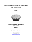
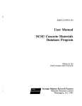
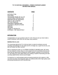
User Manual ST-164 - Dual injector
Artikel-Nr.: 200 164 ...
Description
The ST-164 is an injector unit for admixing liquid detergent concentrates with water using the
venturi principle. Via a selector lever (see photos below) two alternative detergents can be
selected for admixing. A third selector lever position makes it possible to flush the unit clear
without any detergent intake. Via an optional compressed air connection compressed air can
be added to the detergent/water mixture. Any accessory components needed for this can be
found in the spare parts drawing at the end of these Operating Instructions.
Selector lever switching positions
Safety
Hazard
If these instructions are not
followed there is a danger
of physical injury, danger to
life and material damage!
Please comply with the
Operating Instructions!
Incorrect operation can
lead to serious injury. Read the Operating Instructions before you use the appliance.
Rinsing
Detergent 1
Detergent 2
General safety notes
▪ T
o guarantee safe operation the injector unit may only be used in accordance
with these Operating Instructions.
▪ Keep these Operating Instructions in a safe place for later reference.
▪ Please also observe the safety instructions for the detergent and if applicable of
the high pressure cleaner manufacturer.
▪ Do not mix detergents one with the other.
▪ Wear suitable protective clothing and gloves when working.
▪ Never direct the high-pressure jet at persons or other living creatures.
▪ Read the safety data sheets and observe the corresponding safety and handling
regulations.
Info
In addition the required safety and legal regulations for the respective type of use
must be observed. This also applies to all accessories used.
Intended Use
▪ The ST-164 injector unit is designed for admixture of detergents with water and for straightforward rinsing with water.
▪ Only Pressure Equipment Directive (PED) Group 2 liquids may be used as media. In case of doubt contact the equipment
manufacturer.
▪ The unit may only be used with a suitable pressure generator.
▪ The unit is not designed for use with persons (children included) with restricted sensory and mental capabilities due to
lack of experience and/or lack of knowledge unless they are supervised by a person responsible for their safety or if they
have received instruction from that person in use of the equipment.
▪ In general children are forbidden to use this equipment.
Connection lines used and the ST-164 injector unit itself must be flushd clear for 20 seconds prior to any change of detergent. In the case of very powerful detergents please contact the manufacturer who can then assess whether operation
with this unit is possible. Any form of operation of the ST-164 injector unit over and above is deemed impermissible.
Qualified personnel
The bypass injector may only be installed by qualified personnel able to operate the bypass injector properly. Qualified
personnel are persons familiar with installation, commissioning and decommissioning, operation, maintenance and repair and
who hold a qualification appropriate to their work.
page 1, Ver. 1.10
www.rm-suttner.com
User Manual ST-164 - Dual injector
Artikel-Nr.: 200 164 ...
Commissioning
The ST-164 Dual Injector Unit may be secured either with the optionally available wall bracket or with a panel design fitment. Position detergent canisters in the vicinity of the injector unit. They should be no more than 3m distant from the injector unit.
Select the appropriate dosage nozzles.
Connect the intake suction hoses for the detergent to the ST-164 detergent connectors.
Do not confuse hoses and canisters!
Connect a suitable hose to the injector unit outlet.
Connect a suitable spray attachment.
Connect the injector unit to the pressure generator.
Set the injector unit to clear flush (selector lever in
the intermediate position).
Check all connections.
Securing with wall bracket
Assembly set for wall mounting (Product code 20 0168 420)
Pos. Item number Description
1
00 0005 094 Adapter wall bracket
2
00 0005 085 Wall bracket
3
04 0004 180 Hexagon Screw M8 x 45
4
04 0004 175
Plate M8
For ST-164 not necessary
Panel mounting
Place the ST-164 as shown in the panel mounting bracket plate.
Template with panel mounting hole pattern
You can overlay this matching template (see page 8)
on the bracket plate provided and then drill the holes as illustrated.
ST-164 injector with dosage nozzles „intake flow volume“
(5 % * 15 l/min) / 100 % = 0,75 l/min (dosage rate)
=> nozzle selection 1,2 (read from diagram)
Dosage in l/min
Adjusting the dosage rate
Table reading example for dosage
nozzle
Flow volume: 15 l/min
Detergent or disinfectant concentration: 5 %
Calculated in accordance with the following data:
Please note that the maximum mounting plate thickness of 3 mm must not be exceeded.
Concentration (%) * Flow volume (l/min) = Dosage (l/min)
The flow volume can be read from a corresponding nozzle table
without
nozzle
Dosage nozzle bore
Note.: The graph only represents guide values Medium: Water (p=approx. 998 kg/dm3)
page 2, Ver. 1.10
www.rm-suttner.com
User Manual ST-164 - Dual injector
Artikel-Nr.: 200 164 ...
(3 % * 15 l/min) / 100 % = 0,45 l/min (dosage rate)
=> graph setting 2 (read from diagram)
ST-164 dual injector nozzles are
interchangeable. By suitable nozzle
selection it is possible to adjust the
injectors to match virtually all feasible
applications.
The choice of injector nozzle combination influences definitively the quantity
of maximum detergent induces under
suction (concentration) and resistance
of the injector to pressure losses
caused by the accessories (hoses,
spray attachment etc.)
ST-164 with dosage valve ST-161 „intake flow volume“
Dosage in l/min
Sample reading from graph
(for this the optional ST-161 dosage valve is needed)
Flow volume: 15 l/min
Detergent or disinfectant concentration: 3 %
Calculated in accordance with the following formula:
Each injector consists of two nozzles - the injector nozzle itself
and the counter nozzle.
Concentration (%) * Flow volume (l/min) = Dosage (l/min)
The flow volume can be read from a corresponding nozzle table
Scale setting
Note.: The graph only represents guide values Medium: Water (p=approx. 998 kg/dm3)
Counter nozzle
Injector nozzle
Changing injector nozzle and diffusor nozzle
Carry out work on the injector unit clean surroundings. Use suitable tools. Please be careful not to lose small parts. The 4 screws (Pos. 1) must be tightened with a torque of 13,0 Nm.
To change the injector and diffusornozzles first release the four bottom fixing screws (1). You can then remove the lower injector unit (2) together with the PEEK disc (6) from the upper injector unit (7). Remove the PEEK disc (6). Please note that the two O-rings can drop off! By screwing in an M4 screw remove the injector nozzle (4) from the lower injector unit (2). The diffusornozzle can now be removed from the lower injector unit (2) with a screwdriver.
When mounting the diffusor nozzles it must be seen to it that they are screwed in as far as it will go. It is very important that the O-rings are fitted correctly!
Tool for changing a counter nozzle
Screw driver similar
DIN 5265 shape A
Loxeal 56-03
7,0 mm
1,2 mm
page 3, Ver. 1.10
www.rm-suttner.com
User Manual ST-164 - Dual injector
Artikel-Nr.: 200 164 ...
Overview injector nozzles - counter nozzles ST-164
Most applications can be covered by standard combinations
pre-tailored in consultation with us:
For high-pressure applications of 80 bar and above we
recommend:
Combination
1,3 -1,7 1,6 – 2,0
1,8 – 2,3
2,4 – 2,8
Unit
10 – 15 litres
15 -10 litres
20 -25 litres
> 25 litres
For low-pressure applications we recommend:
Combination Unit
2,1 -2,8 25 bar + compressed air
2,4 - -2,8
< 25 bar
Counter-pressure
diagram ST-164
Pressure generator
Detergent
Counter pressure
Changing
dosage nozzles
Dosage nozzles make it possible to restrict the intake suction flow volume or detergent concentrate from both detergent connectors
(Chem 1 and Chem2) so as to adjust the concentration of detergent in the water. You can obtain a basic dosage nozzle set (restrictors) under the following product code: 20 0163 340 Restriction Bag ST-163
For choice of dosage nozzles see ▪
Remove the intake hose.
„Dosage
Adjustment“ Chapter
▪
Withdraw the old dosage nozzle from the induction socket.
▪
Insert the new dosage nozzle into the induction socket.
There is an O-ring for each dosage nozzle. During assembly please ensure that the O-rings are not damaged.
Injector nozzle to large counter nozzle => high intake
level and low counter-pressure tolerance
dosage nozzle
Higher diffusor-pressure tolerance means
that pressure losses caused by fittings,
hoses, sprayguns etc. may also be higher.
Diffusor-pressure tolerance reflects the maximum diffusor-pressure level at which
injector induction suction continues.
page 4, Ver. 1.10
Example:
Input pressure 100 bar, injector nozzle 1.3 and counternozzle 2.8 => 2 litres induction level and diffusor-pressure tolerance 27 bar
Injector nozzle to small counter nozzle => low induction
level and higher counter-pressure tolerancez
Example:
Input pressure 100 bar, injector nozzle 1.3 and counter nozzle 1.7 => 0.5 litre induction level and diffusor-pressure tolerance 52 bars
All details are approximate values only..
www.rm-suttner.com
User Manual ST-164 - Dual injector
Artikel-Nr.: 200 164 ...
ST-164 Operating Modes
Operating Mode 1: Operation without compressed air
The ST-164 injector unit can be used simply as a cleaning medium injector (preferably at high pressure). Here the injector unit is incorporated in the water supply downstream of the pressure generator.
Figure 1a: Selection between two alternative detergents and a clear flush position can be made via the selector lever.
Figure 1b: At pressures > 70 bar foaming detergents can be foamed effectively with an air injector using a separate foam lance with
an air injector. Available foam lances are for example the ST-72, ST-74 and ST-75.
Assembly layout: Use with detergent (Figure 1a)
High, Medium or
Low pressure pump.
Pressure min. 5,6 bar.
Pressure max. 350 bar.
Flow min. 4 l/min.
Cleaning agent 1
Cleaning agent 2
High pressure hose.
ID min. 5/16“. Length 20 m.
ID recom. 3/8“. Length 40 m.
Nozzle
Lance
High pressure gun
ST-1500, ST-2300
Assembly layout: Use with foaming agent (Figure 1b)
Highpressure pump.
Pressure min. 80 bar.
Flow min. 8 l/min.
Foam agent
Foam lance with Air injector
ST-72, ST-74, ST-75
page 5, Ver. 1.10
High pressure hose.
ID min. 5/16“. Length 20 m.
ID recom. 3/8“. Length 40 m.
High pressure gun
ST-1500, ST-2300, ST-2700
www.rm-suttner.com
User Manual ST-164 - Dual injector
Artikel-Nr.: 200 164 ...
Operating Mode 2: Operation with
compressed air
ST-164 check valve (Product Code 200 164 370)
To install the ST-164 check valve you must first unscrew the blanking plug with O-ring from the ST-164 injector unit (Diagram 1). The
ST-164 check valve is then screwed in (Diagram 2). Compressed
air can then be connected to the ST-164 non-return valve.
Diagram 1
Diagram 2
Foaming with compressed air is particularly suited to generating foam at low water pressures: 3-70 bar
Assembly layout with detergent
Shut-off
valve open
High, Medium or Low
pressure pump.
Pressure min. 5,6 bar.
Pressure max. 350 bar.
Flow min. 4 l/min.
Check valve (optional)
Air
pressure
regulator
Air
compressor
Foam agent
Foam hose.
ID recom. 1/2“.
Length max. 20 m.
Foam lance
Foam gun
203 100 605, 203 100 610, ST-2725, ST-3100, ST-3300
203 100 630, 502 808
Troubleshooting
Injector does not suck in foaming agent or detergent from the container or no foam is generated:
ST-164 without compressed air
ST-164 with compressed air
▪ Dosage nozzle blocked - clear nozzle with thin wire as
▪ Dosage nozzle blocked - clear nozzle with thin wire as necesnecessary. If strongly scaled select new dosage nozzle.
sary. If strongly scaled select new dosage nozzle.
▪ Selector lever in wrong position
▪ Selector lever in wrong position
▪ Intake suction hose damaged
▪ Intake suction hose damaged
▪ Intake suction hose not immersed in foaming agent
▪ Intake suction hose not immersed in foaming agent
▪ High-pressure hose too long /nominal bore to small ▪ Air connection not correct or not connected in the first place
(minimum bore 8)
▪ Compressed air line shut-off valve closed
▪ Foam lance used without injector => select foam lance
▪ Connection of a pressure reducer in the compressed air line with injector
(2 – 6 bar)
▪ Check non-return valve whether piston operates smoothly
▪ High-pressure hose too long /nominal bore to small (
or shows signs of damage, replace as necessary.
minimum bore 12)
▪ Foam lance nozzle too small => select lance with larger air ▪ Foam lance used with air injector
injector nozzle
▪ Check non-return valve whether piston operates smoothly or
shows signs of damage, replace as necessary..
▪ Equipment with too small cross-sections used.
page 6, Ver. 1.10
www.rm-suttner.com
User Manual ST-164 - Dual injector
Artikel-Nr.: 200 164 ...
Spares
Below is a list of individual ST-164 parts: Please note: It is only allowed to use original, high-strength screws.
Pos.
Item-No.
Description
1
040 004 165
Headless screw
2
040 000 631
pan head screw
3
200 163 360
Check valve Peek 4
040 004 161
Screw M6x70
5
040 002 535
Fan shaped washer
6
040 004 206
screw
7*2 050 001 160
O-Ring 4x1
8
040 004 827
control channel
9
020 001 183
Blind Plug yellow
10
020 001 182
Blind Plug blue
11
040 004 170
Bolt
12
040 00 4152
screw M6x20
13
040 003 525
Cover
14
040 003 545
Piston
15
040 003 540
Distance ring
16
040 004 825
turning device
17
040 004 822
upper part
18
040 001 720
Pressure disc
19* 050 002 305
O-Ring 27x1,5 viton
20* 050 002 315
O-Ring 23x1,5 viton
21* 050 002 310
O-Ring 19x1,5 viton
22* 050 002 322
PTFE Slide seal ring
23
middle part
040 004 823
24* 050 002 330
O-Ring 27x1,5
25
020 005 086
cap ST-164
26
020 005 089
notch
27
060 001 180
spring bolt
28
020 005 087
cover ST-164
29
040 004 820
lever holder
30
040 003 530
Lever
31
020 005 115
Ball handle
32
040 000 060
Pin 5x20
33* 050 000 385
o-ring
34
020 005 088
Peek disc
35
040 004 828
blind plug
36* 050 000 435
O-Ring
37
020 005 100
Cover blue
38
020 005 105
Cover yellow
39
040 003 523
Nozzle 2,3
40 040 003 535
41*2 050 002 301
Injector nozzle
42
200 044 490
ball bearing
43
040 004 824
base part
page 7, Ver. 1.10
O-Ring 7x1,5 NBR 90Shore
31
30
1
29
10
32
2
9
27
26
28
6
13
25
12
490
* 200 164* 200
490 -164
Reparatur-Set
Repair-Kit
ST-164
complete
ST-164
komplett
22
14
20
21
15
11
19
18
42
7
8
16
7
41
17
34
37
33
41
40
35
24
19
36
4
5
38
39
3
43 23
Disposal
Please dispose of old unit in an environmentally-friendly manner.
Old units contain valuable recycling materials which should
be forwarded to a recycling facility. Please dispose of old units
therefore via appropriate collection points.
www.rm-suttner.com
User Manual ST-164 - Dual injector
Artikel-Nr.: 200 164 ...
Template with panel mounting hole pattern
8,5
Ø
41,3
10,1
,5
Ø8
Ø
31
You can overlay this matching template on the bracket plate provided and then drill the holes as illustrated.
Ø
7
Ø
7
43
page 8, Ver. 1.10
www.rm-suttner.com