1
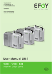
User Manual EFOY 600 / EFOY 900 / EFOY 1200 / EFOY 1600 / EFOY 2200 ENGLISH 1. Table of Contents 1. Table of Contents 1. Table of Contents 2. Introduction 2.1 Foreword 2.2 Safety Information 2.3 Safety notice for methanol 2.4 Normal Operation 2.5 Declaration of Conformity 2.6 Seals of Approval 2.7 Warranty 2.8 Warranty extension 2.9 Disposal 4 4 5 7 7 8 8 9 9 10 3. Configuration 3.1 Standard Equipment 3.2 Overview 3.3 Remote Control 3.4 Specifications 11 11 12 12 13 4. Installation 4.1 Tools and Materials 4.2 Space Requirements 4.3 Securing the unit 4.4 Off-heat duct 4.5 Connecting the Exhaust Hose 4.6 Installing the fuel-cartridge holder 4.7 Electrical Connections 4.8 Connection via the Central Electrical Box (EBL) 4.9 Connection directly to the battery 4.10 Connecting the Remote Control 15 15 16 17 18 19 21 22 23 24 25 5. Operation 5.1 Connecting the Fuel Cartridge 5.2 Select Language 5.3 Display Information 5.4 Automatic Operation 5.5 Switching on the Fuel Cell 5.6 Switching Off the Fuel Cell 5.7 Battery protection 5.8 Automatic Antifreeze Feature 27 27 30 31 32 33 34 35 36 2 2 English 1. Table of Contents 5.9 Storage 37 6. Maintenance 6.1 Service 6.2 Cleaning 39 39 40 7. Troubleshooting 7.1 Safety 7.2 Problems and Solutions 7.3 Problems without Error Messages 7.4 Replacing Service Fluid 41 41 42 44 45 8. Appendix 8.1 Output characteristic 47 47 3 2. Introduction 2. Introduction 2.1 Foreword Thank you for purchasing an EFOY product. We hope that you will enjoy your new unit. Please read these instructions first before using. Should you have any questions about installation or operation, please consult the EFOY hotline. SFC Energy AG Eugen-Sänger-Ring 7 D-85649 Brunnthal-Nord Hotline: +49 89 / 673 5920 Freecall: 00800 / 732 762 78* Fax: +49 89 673 592 369 [email protected] www.efoy.com *The toll-free number is available in the following countries: Germany, Belgium, Denmark, France, Great Britain, Italy, the Netherlands, Norway, Austria, Sweden, Switzerland and Spain. 4 English 2. Introduction 2.2 Safety Information Read the instructions before operating and keep them nearby. Be sure to follow all directions in the manual. Do not open unit or fuel cartridges. Do not use force to open cartridges and do not refill them. Any modifications to the unit may affect safe operation, will lead to a loss of license and will void the warranty Use only original EFOY equipment. Do not store unit and fuel cartridges at temperatures above 45° C. Do not operate at temperatures above 40° C. Keep away from heat and direct sunlight. Store the unit where there is no danger of freezing, or use the automatic antifreeze feature. Do not smoke when handling the unit or the fuel cartridges. Keep away from heat and open flame. There is a danger of fire if methanol leaks out following an accident, or if the unit or the fuel cartridge has been damaged. Keep away from open fire and make sure area is well ventilated. Small amounts of methanol which may leak out will evaporate without leaving any residue. Keep unit and fuel cartridges (including empty or partially filled cartridges) out of children’s reach. Operate the unit only in accordance with instructions and keep operating area well ventilated. Do not block exhaust. Avoid inhaling exhaust fumes directly or for prolonged periods of time. 5 2. Introduction There is no risk of coming into contact with methanol provided that you handle the unit and fuel cartridges in accordance with instructions. We are required by law to print the following notice. Methanol is toxic if inhaled, ingested or if it comes into contact with skin. Irreparable damage may occur if inhaled, ingested or if it comes into contact with skin. In the event of an accident or if nausea occurs, consult a physician immediately. Be sure to bring the fuel cartridge label or these instructions to the consultation. System exhaust may contain harmful components. Avoid inhaling exhaust directly or for prolonged periods of time. Use the exhaust hose to conduct exhaust gases to the exterior. Improper use or improper connection to other electrical devices may result in damage. WARNING In addition to these safety instructions, please observe the passages in bold type. Otherwise, you may endanger yourself and others. 6 English 2. Introduction 2.3 Safety notice for methanol WARNING You are given the methanol in the form of safe, tested fuel cartridges that protect you from coming into direct contact with the contents if used correctly. We are required by law to print the following notice. Methanol is easily flammable. Methanol is toxic if inhaled, ingested or if it comes into contact with skin. In the event of an accident or if nausea occurs, consult a physician immediately. Be sure to bring the fuel cartridge label or the methanol material safety data sheet to the consultation. Storage and transport of methanol may be subject to statutory regulations. More information is provided in the methanol safety data sheet on our website www.efoy.com or by SFC directly 2.4 Normal Operation The EFOY 600, EFOY 900, EFOY 1200, EFOY 1600 and EFOY 2200 are automatic charging devices for 12V lead batteries. The unit may be used only to charge lead batteries that conform to the specifications in Chapter 3.4, page 13). The specifications allow for solid-state operation (see Chapter 3.4) on boats and on motor vehicles. Operate only with original-equipment EFOY fuel cartridges. The unit is not intended for emergency medical power generation, or for powering life-sustaining or agricultural devices. 7 2. Introduction It is permissible to connect units in parallel to increase the charging current. The series connection of units to increase the voltage is not permitted. Do not operate unit if housing is damaged. 2.5 Declaration of Conformity SFC Energy AG, Eugen-Saenger-Ring 7, 85649 BrunnthalNord declares that the EFOY 600, EFOY 900, EFOY 1200, EFOY 1600 and the EFOY 2200 conform to the European Community’s 2004/108/EG guidelines for electromagnetic compatibility. The following norms apply: DIN EN 61000-6-1, DIN EN 61000-6-3 2.6 E 24 Seals of Approval These units have been tested in accordance with ECE Regulation No. 10 for electro-magnetic compatibility. Operation in motor vehicles is permitted. Approval number: E24 10R-020234 These units have undergone voluntary testing by TÜV SÜD for conformity with the basic requirements of IEC 62282-5 and have been awarded the seal of approval for product safety. 8 English 2. Introduction 2.7 Warranty The warranty period begins when the new unit is purchased. Your proof of purchase (receipt, invoice, etc.) can be used as a record of this date. Please keep these documents carefully. Our warranty services are based on the SFC warranty conditions which are valid at the time of purchase. Service For technical queries on EFOY fuel cells, our EFOY customer service can be reached during office hours at the following numbers: Freecall (Germany): 00800 / 73 27 62 78* From any other country, please dial: +49 89 / 673 5920 SFC Energy AG Eugen-Sänger-Ring 7 85649 Brunnthal-Nord Germany Fax.: +49 89 / 673 592 369 [email protected] www.efoy.com *The freecall number is available from the following countries: Germany, Belgium, Denmark, France, Great Britain, Italy, the Netherlands, Norway, Austria, Sweden, Switzerland and Spain. 2.8 Warranty extension The EFOY warranty certificate gives you maximum security and reliable service. When you pay the one-off fee, you receive the EFOY warranty certificate for a 5-year manufacturer’s warranty. The EFOY warranty certificate is available directly from SFC Energy AG, the manufacturer of EFOY fuel cells. Simply fill in the form at www.garantie.efoy.com/en or call +49 89 / 673 5920 for further information. 9 2. Introduction 2.9 Packaging Disposal Packaging protects your unit during shipping. All materials used are environmentally compatible and recyclable. We recommend saving the packaging for eventual winter storage. Should you nevertheless wish to dispose of the packaging, please do so properly. Your dealer or your local recycling center can provide information about proper disposal. WARNING Danger of Suffocation! Keep packaging away from children. Plastic wrapping and cartons may cause suffocation. Fuel Cartridges Old Units Sort empty fuel cartridges with plastics. Dispose of partly filled fuel cartridges in the same manner as solvents or paint. Old units are still valuable! Proper disposal can yield valuable raw materials while protecting the environment. The EFOY hotline: Tel.: +49 89 / 673 5920 or 00800 / 732 762 78* can advise you about returning old units. 10 English 3. Configuration 3. Configuration 3.1 Unit Remote control with data line RC1 Standard Equipment The following is standard equipment: Unit Remote control with data line RC1 (10 metres long) Fuel-cartridge holder with belt FH 1 Mounting plate with belt MP 1 Exhaust hose (1.5 m) EH 1 Off-heat duct OD1 (consisting of off-heat flange, offheat bow, off-heat tube, external cover and fixing screws) Service fluid UM1 user manual Charge line CL4 Fuel-cartridge holder with belt FH1 Charge line CL4: Mounting plate with belt MP1 Connecting line to fuel-cell 1m Exhaust hose EH1 Off-heat duct OD1 Service kit Battery fuse power 15 A Length 0,5m 11 Battery fuse sense 2.0 A Length 0,5m 3. Configuration 3.2 Overview 1 2 3 4 5 6 7 3.3 auto reset ! Charge line connection Remote-control connection RC 1 Data interface Fuel-cartridge connection Connection for EH 1 exhaust hose and nozzle for service fluid Cooling inlet (reverse) Warm-air outlet and connection for off-heat duct Remote Control 1 2 3 4 5 6 7 Display Information button and language-selection button >> On/Off button Button for automatic operation auto Yellow warning light “Please change fuel cartridge“ Red error warning light Reset button reset 12 English 3. Configuration 3.4 Specifications Performance EFOY 600 EFOY 900 EFOY 1200 EFOY 1600 EFOY 2200 25 W 38 W 50 W 65 W 90 W Charge capacity 600 Wh/Day (50 Ah/Day) 900 Wh/Day (75 Ah/Day) 1200 Wh/Day (100 Ah/Day) Nominal voltage 12 V 12 V 12 V 12 V 12 V Charging current @ 12 V 2.1 A 3.1 A 4.2 A 5.4 A 7.5 A Turn on threshold* Ubatt < 12.3 V Ubatt < 12.3 V Ubatt < 12.3 V Ubatt < 12.3 V Ubatt < 12.3 V Cut off threshold* Ubatt >14.2 V Ubatt >14.2 V Ubatt >14.2 V Ubatt >14.2 V Ubatt >14.2 V Required starting voltage >9 V >9 V >9 V >9 V >9 V Quiescent current requirement 15 mA 15 mA 15 mA 15 mA 15 mA 0.9 l/kWh 0.9 l/kWh 0.9 l/kWh 0.9 l/kWh 0.9 l/kWh Product Rating Methanol requirement Compatible batteries** 1560 Wh/Day 2160 Wh/Day (130 Ah/Day) (180 Ah/Day) 12 V rechargeable (lead-acid or lead-gel) batteries 10 - 100 Ah 15 - 150 Ah 20 - 200 Ah 40 - 250 Ah 60 - 350 Ah 23 dB(A) 23 dB(A) 23 dB(A) 23 dB(A) 23 dB(A) 6 kg 6.2 kg 7.4 kg 7.6 kg 7.9 kg General Specifications Sound pressure level at 7 m Weight Dimensions (LxWxH) 43.5 x 20.0 x 27.6 cm Environmental conditions Space requirement (LxWxH) 51 x 35 x 30 cm (minimum) Inclination along the direct axis continual: 35° temporary (<10min): 45° Inclination along the quadrature axis continual: Operating temperature -20 to +40 °C Start temperature +5 to +40 °C Storage temperature +1 to +45 °C 20° * factory setting - can be modified with Interface Adapter and PC ** The default values are preset optimally ex works for the specified battery sizes. If the battery capacities deviate greatly from these sizes, please contact your specialist retailer. 13 3. Configuration Instrumentation Operation via remote control with four buttons and multilingual display Electrical interface MNL 4-prong plug Type Tyco Electronics AMP Universal Mate-N-Lok (Mfr. No. 350779) Fuel Cartridge M5 M10 Volume 5 liter 10 liter Weight 4.3 kg 8.4 kg Dimensions (L x W x H) 19.0 x 14.5 x 28.3 cm 23.0 x 19.3 x 31.8 cm 14 English 4. Installation 4. Installation WARNING Securely fasten unit and fuel cartridges when using on board motor vehicles. Do not operate unit if there is danger of explosion. Unit is not watertight. Make sure that no water can enter. Keep unit and fuel cartridges away from children, temperatures in excess of 45° C and direct sunlight. 4.1 Tools and Materials You will need the following tools and sealants to install the fuel cell: electric drill jigsaw screwdriver hexagonal (Allen) wrench sealant such as Sikaflex Use the following screws, depending on the mounting surface (screws are not included): 8 screws to attach the mounting plate 4 screws to attach the remote control 4 screws to attach the fuel-cartridge holder cable clamps and fixing screws, if needed 15 4. Installation 4.2 Space Requirements Installation should be carried out by trained personnel only. Wear proper work clothes. Avoid flowing garments and wear a hair net if you have long hair. Clothing and hair can get caught in moving or rotating parts such as in a drill. Be sure to leave enough space behind the installation area when drilling or cutting out openings. Also be sure to follow the tool manufacturer’s safety instructions. Solvents used in sealants may emit fumes. Make sure that there is sufficient ventilation and follow the instructions for the sealing compound. Make sure when choosing a location, that the temperature ranges between –20° C and +40° C. WARNING This unit generates heat, thus requiring ventilation. Please take this into account when considering possible locations. Provide for a vent opening measuring at least 10 cm across when installing. Use the off-heat duct (included) to remove warm air. min. cooling 10 cm air Install only in upright position. Use the mounting plate (included). Make sure that the device does not exceed the maximum inclination. Inclination along the direct axis: continual: 35° temporary (<10min): 45° Inclination along the quadrature axis: continual: 20° 16 English 4. Installation All electrical connections, the fill opening for service fluid and the fuel cartridge should be easily accessible. Make sure that the fuel cartridge is located within reach of the connecting hose (30 cm) and that the hose is neither kinked nor crushed. max. 30 cm The fuel-cartridge hose and the exhaust hose may not be damaged. Do not substitute another hose for either of the two. Use only original-equipment EFOY hoses. 4.3 Securing the unit Select a suitable location as described in Chapter 4.2, paying attention to the dimensions in Chapter 3.4. 1. Run the belt in the groove under the mounting plate. 2. Secure the mounting plate tightly to the desired location. Use eight proper screws and dowels, if necessary, so that the mounting plate cannot shake loose in case of an accident. 3. Place the unit onto the mounting plate. 4. Strap the unit tightly to the mounting plate. 17 4. Installation 4.4 Off-heat duct The off-heat duct (included) extracts warm air so that the unit can also be operated in close quarters. Use the bow to conduct warm air to the side. warm air min. 10 cm cooling air exhaust If you do not need the off-heat bow, you can disconnect it from the off-heat flange and connect the off-heat tube directly to the flange. Make sure that the off-heat tube is not kinked; use a second bow if needed. min. 10 cm cooling air exhaust warm air Sink the screws for the off-heat flange into the holes provided. Then pass the off-heat tube to the exterior. You will need an opening with a 100 mm diameter. Be careful of electrical lines when drilling. Your dealer can provide information as to the location of lines. 18 English 4. Installation Pass the off-heat tube through the opening; any excess may be shortened. It may be necessary to use an external face plate to protect the outlet. Use a suitable sealant to prevent moisture from penetrating into the body or into the interior. 4.5 Connecting the Exhaust Hose Within the fuel cell methanol and oxygen are converted into water and carbon dioxide. This chemical reaction generates off-heat which needs to be conducted together with water vapour and carbon dioxide to the outside. WARNING Connect the enclosed exhaust hose and always evacuate the exhaust gases from the installation compartment or site to outdoors. Exhaust gasses contain moisture and may exceed 60° C, causing scalding. Exhaust byproducts may contain injurious substances. Avoid inhaling exhaust directly or for long periods of time. To prevent freezing in winter, the exhaust hose may not too long and should be cut diagonally to avoid the emergence of drops. At no time may siphoning occur in the hose. Make sure that the hose is neither clogged nor blocked. 19 4. Installation Routing the exhaust hose Up Down Avoid siphoning Remove the cap from the exhaust port. Retain the cap for winter storage or for possible returns. Attach the exhaust hose (included) to the exhaust port. Take the exhaust hose out of the installation space and seal the opening for the exhaust hose with suitable sealing material. The exhaust (which also includes condensate) can be directed outside, to a wastewater tank or other suitable container (on yachts also in the bilge). But make sure that there is a hose that allows the gasses including the carbon dioxide to evaporate. The exhaust hose should be as short as possible. The part of the hose at the outside should not be longer than 5 cm. Cut diagonally the end of the hose to avoid the emergence of drops. The exhaust hose can be shortened as required. The opening must have a diameter of 10 mm. Make sure the exhaust hose has no kinks or blockage and that exhaust can escape freely. 20 English 4. Installation 4.6 Installing the fuel-cartridge holder WARNING Keep fuel cartridge and all reserve cartridges away from children. Keep cartridges away from heat and out of direct sunshine. Secure fuel cartridge and all reserve cartridges so that they can not shift. Make sure that the fuel-cartridge connecting hose is neither crushed nor kinked. warm air Do not place fuel cartridges or reserve cartridges in front of the air intake or outlet! Do not place objects such as reserve fuel cartridges in front of the air intake or outlet. Place fuel cartridges next to or in front of the unit as illustrated. electrical connection Install unit and fuel cartridge at the same level. Secure the fuel-cartridge holder with four suitable screws and dowels, if necessary, so that it will not shake loose in the case of an accident. 21 4. Installation 4.7 Electrical Connections WARNING All work should be carried out by qualified technicians in accordance with technical regulations. Improper connections or the use of wrong gauge wires could result in fire. All wires must be properly insulated and have adequate voltage rating. All connections must be tight. The use of uninsulated wires and contacts is not permitted. Use the wire harness (included) to connect the unit. The circuit connecting the battery must contain a fuse. Alternatively, use the fuse (available as optional equipment) to connect the battery. Check the polarity (see illustration) before connecting the unit. Both sensor and power lines must always be connected. Always use separate lines for charging (power) and for voltage metering (sensor) to the battery. Otherwise, the flow of current will cause false readings. The charging lines consists of four leads that must be connected to the battery as follows: Power lead: This lead carries current from the fuel cell to the battery. Power lead Sensor lead: This lead measures battery voltage. Sensor lead 22 English 4. Installation To minimize current loss in the leads, the following cross section is recommended, should the battery charging cable be insufficient: Length [m] <5m 5 – 10 m 10 – 15 m min. cross section 2.5 mm² 4 mm² 6 mm² Option: Extension sense line 8 m (Art. No. 151 906 005) Extension Power line 8 m (Art. No. 151 906 006) 4.8 Connection via the Central Electrical Box (EBL) red brown Fuse 2A 4 1 5 3 2 or 6 1. 2. 3. 4. 5. 6. 7. 7 unit connecting line to fuel cell extension sense line (optional) battery fuse 2 A battery extension power line with 2- or 3- pole plug (optional) Central electrical box (EBL) 23 4. Installation 4.9 Connection directly to the battery red brown Fuse 2A 4 1 5 3 2 6 Fuse 15A 7 1. 2. 3. 4. 5. 6. 7. unit connecting line to fuel cell extension sense line (optional) battery fuse sense 2 A battery extension power line with 3-pole plug (optional) battery fuse power 15 A 24 English 4. Installation 4.10 Connecting the Remote Control The remote control (1) displays the current status and is used to control the device. Mount the panel where it is easily accessible such as in the cockpit. 1 Flush mounting: 2 If installing the panel flush with the surface of the unit, make sure that there is a sufficient opening for the electronic components behind the opening. 3 4 Flush mounting: 1 2 3 4 The secure the control panel (1) with four suitable screws (4) and place the frame (3) over the control panel. remote control opening frame screws 1 Use templates for drilling and sawing when flush or surface mounting (2). Use a drill to start the opening and then cut out the rest of the opening with a keyhole or compass saw. Surface mounting: 2 Secure the surface mount with two screws. Connect the remote control with the DL 1 data line (included). 3 4 Then secure the control panel (1) with four suitable screws (4) and place the frame (3) over the control panel. Surface mounting: 1 2 3 4 remote control surface mount frame screws 25 4. Installation Connect the remote control with the DL data line (included). If the DL 1 data line is not long enough, you can replace it with a commercially available network line that is longer or shorter (Category 5 patch cable). Then insert the plug into the left socket on the unit marked “Remote Control“. 26 English 5. Operation 5. Operation CAUTION Before connecting to the electrical system, make sure the unit has been positioned properly and that the electrical system is protected by fuses (as described in Chapter 4.7) Do not operate at temperatures above 40° C or below - 20° C. If device has been exposed to temperatures under 0° C without being connected to a battery or with insufficiently filled fuel cartridge, it must stand at room temperature for 24 hours before operating. When the temperature exceeds 40°C, the device shuts down automatically and restarts when the temperature decreases. 5.1 Connecting the Fuel Cartridge WARNING For safety’s sake, use only original EFOY fuel cartridges. Do not smoke while changing the cartridge and avoid open flames! Do not expose fuel cartridges to temperatures above 45°C. Do not place the fuel cartridge in front of the air intake or outlet. Original-equipment EFOY fuel cartridges contain EFOY-approved methanol. Even slight impurities in commercially available methanol may cause permanent damage to the unit and may void the warranty. Please observe the notices on methanol in Chapter 2.3. 27 5. Operation Note: When the cartridge is empty, “Please change fuel cartridge“ will appear on the remote control and the yellow light will blink. The cartridge may be changed while the system is running. Unscrew the empty fuel cartridge and remove. Close each cartridge tightly with the cap after use. EFOY fuel cartridges are intended for one-way use only. They may not be refilled. Sort empty fuel cartridges with plastics. Dispose of partly filled fuel cartridges in the same manner as solvents or paint. 1 Place a new sealed original-equipment EFOY fuel cartridge into the fuel-cartridge holder (1). 28 English 5. Operation 2 Fasten the belt on the fuel-cartridge holder (2). Do not attach fuel cartridges without a fuel-cartridge holder. Only remove the childproof cap when the new fuel cartridge has been placed into the fuel-cartridge holder (3). 3 Screw the connector onto the new fuel cartridge. Press reset on the control panel to extinguish the yellow warning light and the maintenance message. Note: A bottle of service fluid is included with the product. Please carry it at all times. Service fluid only has to be refilled if the EFOY fuel cell displays “Please refill service fluid”. The EFOY fuel cell is already filled with service fluid on delivery. Service fluid may be required in extremely warm environments. See page 45 for instructions on refilling the service fluid. 29 5. Operation 5.2 Select Language Press >> on the control panel for 2 seconds. The control panel will display the language currently selected. Deutsch The following languages are available: German (factory setting) English French Italian Dutch Spanish Continue pressing >> until the desired language appears. Then hold >> 2 more seconds in order to set your language choice. 30 English 5. Operation 5.3 Display Information The second line of the display provides information about normal operation, errors or malfunctions (see Chapter 7). The first line indicates the operating mode selected, such as “Automatic“. Charging mode The unit charges the battery as needed or assists the battery in providing output. The second line of the display will indicate “charging mode“ as long as the unit is providing voltage to the electrical system. Automatic The device goes through a cold start phase of about 20 minutes before reaching its full rated output. Automatic Start phase Automatic Standby Automatic Please change fuel cartridge If the battery is sufficiently charged and the unit is not providing input, the unit will remain in the standby mode. Should the device detect a malfunction such as an empty fuel cartridge, it will shut down and advise you how to correct the situation. (“Please change fuel cartridge“.) Resume automatic operation using the reset button after the error has been corrected. (See also Chapter 7 Troubleshooting). Further displayed information By pressing the >> button, you can get following information: Automatic Battery voltage Charging current Voltage 13.6 V Automatic 4.6 A Please note that the device interrupts power generation briefly several times an hour during normal operation and a charging power of 0.0 A is displayed then. 31 5. Operation Automatic Firmware version Firmware V06 11.02 L 12 V QB Please check on a regular basis (at least once a year), if software updates are available. Automatic Total operating hours Operating hours 500 h Displays serial number (from production year 10/2009) Automatic 100600-934-12345 The standard display will be restored after about 30 seconds. Alternatively, you can return to the standard display by pressing >> again. By pressing >> for approximately 2 seconds, you will obtain the language menu (see Chapter 5.2). 5.4 Automatic Operation Automatic operation will begin the moment that you connect the unit to a battery. The unit will monitor battery voltage by itself. The fuel cell switches on automatically if the battery voltage falls below 12.3 V. The battery is then charged until the deactivation threshold, 14.2 V, is reached. Note: To guarantee optimal battery maintenance, it is important that the charge current is not stopped abruptly when the deactivation threshold is reached. For this reason, the EFOY continues to charge for up to 3 h after the deactivation threshold set is reached (by default, 14.2 Volt is preset). The recharging period depends on the battery voltage and the electricity consumption. The device goes through a cold start phase of about 20 minutes before reaching its full rated output. In normal operation the current generation is interrupted briefly a few times a second. 32 English 5. Operation 5.5 Switching On the Fuel Cell If desired, you can switch on the unit manually regardless of the battery voltage. The unit will then be in the “charging mode“. This function is only possible when the battery voltage is below 13.2V On Charging mode Press on the control panel once if the unit has been switched off, and twice if it is operating in automatic mode. The unit will start up regardless of the battery voltage and will continue charging until it reaches the cutoff point (Ubatt >14,2 V und Iout < 2A – 4A for EFOY 2200). The device will then switch to automatic mode by itself and will only charge if the battery or the demand for power requires it. 33 5. Operation 5.6 Switching Off the Fuel Cell Press device. on the remote control to switch off the The unit will gradually shut down, performing various function checks as it does so: Off Shutting down To protect components, the unit must run at least 30 minutes before shutting down. If the unit is shut off beforehand, it will continue running until 30 minutes have elapsed. The message “Shutting down” will appear in the display. Leave the fuel cartridge and the battery connected during this time. Please note that the fuel cell will only start up if it is connected to an intact battery and full fuel cartridge. The fuel cell will not switch on if the battery is damaged. 34 English 5. Operation 5.7 Off Battery protection Battery protection The EFOY fuel cell has an integrated battery protection function. This function prevents deep discharge of the battery when the operating mode is set to “Off”. Battery protection is automatically activated when the battery voltage is lower than 11.2 V for more than 15 minutes. The battery protection charging mode ends when the voltage reaches 12.8 V. This function only serves to protect the battery, and does not recharge it. Off Battery protection -> to shut down press off Press the button to switch off the fuel cell after the battery protection function starts. The function is reactivated automatically when the unit is switched on or operated in automatic mode. Note: If you stop protective charging manually, battery protection is deactivated until the fuel cell is started again. Deep discharge can damage your battery. If battery protection starts repeatedly, please check your system. Battery protection only functions when a full EFOY fuel cartridge is connected. 35 5. Operation 5.8 Off Antifreeze mode Automatic Antifreeze Feature This unit features an intelligent antifreeze feature. The unit can keep itself warm at temperatures below 3° C as long as it is connected to a working battery and it is supplied with methanol. If the unit is in antifreeze mode, the message “Antifreeze mode” will appear on the second line. The first line will indicate the current operating mode, for example “Off”. The antifreeze function works only as long as a fuel cartridge and a sufficiently intact battery are connected. The unit will not be able to start if the battery voltage falls below 10.5 volts. Please note that the unit will not recharge the battery if the voltage drops below 10.5 volts. CAUTION Please observe the following maintenance tips for storage and winter operation: 1 To cut energy costs, we recommend dismounting the unit and storing it away from cold if it is to be inactive for longer periods of time. Dismounting is easy; it requires just a few steps, no tools and no particular technical finesse. Store the unit in the original carton. 2 If, despite precautions, the unit does freeze, let it thaw in a warm place for approximately 24 hours before operating. Please note that the unit’s performance may diminish if it freezes repeatedly. Running in straight antifreeze mode, the unit will consume approximately 10 liters of methanol in the course of a five-month Central European winter. 36 English 5. Operation 5.9 Storage Off Press unit. Wait until the unit has shut down and the display has disappeared (approx. 30 min.). Unplug the charging line and the data line for the remote control. Store the plugs and lines in a cool, dry place. WARNING Do not smoke when handling unit and fuel cartridge. Keep away from open flame! Unscrew the fuel cartridge and close it with a cap. Keep all elements clean. Shutting down on the remote control to switch off the WARNING Keep unit and fuel cartridges – even empty or partially empty cartridges – away from children Remove the exhaust hose. Keep it clean and place a cap over the exhaust outlet. Remove the off-heat tube and the off-heat bow if necessary. Release the belt and lift the unit off the mounting plate. CAUTION Store the device in a cool place but over 1 °C, since the automatic frost protection system only functions with connected fuel cartridges and sufficiently charged batteries. (see Section 5.8) 37 5. Operation CAUTION If the device is exposed to temperatures below 0 °C without connected batteries and sufficiently filled fuel cartridges (frost protection), it must be thawed out for approximately 24 hours at room temperature before commencing operation. When transporting the device, use suitable packaging, e.g. the original packaging, and cushion the device to protect it from shocks. The device must be standing upright when transported. 38 English 6. Maintenance 6. Maintenance 6.1 Service WARINING Do not open unit! Unauthorized tampering may jeopardize safe operation and void any warranty. The unit does not contain any components that you can service or repair yourself. The unit is maintenance free under normal operating conditions. Please check on a regular basis (at least once a year), if software updates are available. EFOY Updater – Update your EFOY fuel cell quickly It’s really easy: Simply connect the EFOY Updater to the EFOY fuel cell and the update runs automatically. For further information on firmware updates, please contact your service partner or check our website: www.efoy.com/en/updater Or Freecall: 00800 732 762 78 Hotline: +49 89 673 5920 [email protected] 39 6. Maintenance 6.2 Cleaning WARNING Switch off device before cleaning and unplug the battery charging cable. The device is not watertight. Make sure that moisture cannot get inside. Clean only with a soft cloth dampened with a mild detergent. Reconnect the battery charging cable after cleaning so that the antifreeze feature remains activated. (See Chapter 5.8). 40 English 7. Troubleshooting 7. Troubleshooting 7.1 Safety WARNING Do not open unit! It contains no components that you can repair yourself. Contact SFC Energy AG if you are unable to correct a malfunction using these instructions. SFC Energy AG Eugen-Sänger-Ring 7 D-85649 Brunnthal-Nord Hotline: +49 89 / 673 5920 Freecall: 00800 / 732 762 78* [email protected] www.efoy.com *The toll-free number is available in the following countries: Germany, Belgium, Denmark, France, Great Britain, Italy, the Netherlands, Norway, Austria, Sweden, Switzerland and Spain. 41 7. Troubleshooting 7.2 Problems and Solutions The control panel signals problems via a red and/or yellow light and a running message on the second line of the display. The messages will assist you in solving the problem quickly and easily. Press the reset button on the control panel AFTER the problem has been solved. Message Solution Check battery or No connect or Check connection Battery voltage is too low. Interruption: Surroundings too warm (Error 32, 41) Ambient temperature is too high. Unit will start automatically as soon as temperature drops below 30° C. Please contact service (Error 1, 10, 13, 14, 15, 16, 17, 70, 73, 75, 76, 80, 83, 84) Call the hotline at. Please check exhaust hose (Error 11, 12, 18) Check that the exhaust hose has been properly connected and arrange it so that condensation cannot form. If battery voltage is under 10.5 V, check connection between unit and battery (see Chapter 4.710). Freecall: 00800 / 732 762 78* Hotline: +49 89 / 673 5920 [email protected] www.efoy.com Check for kinks. Clean hose if necessary and keep opening clear. Shorten exhaust hose if condensation forms. 42 English 7. Troubleshooting Message Solution Please change fuel cartridge (Error 20, 21, 22, 23) Insert a new fuel cartridge as described in Chapter 5.1. Check cartridge hose for kinks. Check hose and connection for dirt. Position fuel cartridge on the same level as unit. Check connection and screw cartridge on tightly. Please refill service fluid (Error 30, 31) Check that exhaust can escape and that ambient temperature is below 40° C. Then add service fluid (see Chapter 7.4). Please defrost device slowly (Error 40) Unit has been exposed to temperatures below 0 °C without being connected to a battery and sufficiently filled fuel cartridge (automatic antifreeze feature). Let stand at room temperature for approx. 24 hours. Please check battery voltage (Error 50, 51, 52, 53) Error 50: Battery voltage is too low (sense line). Error 51: Battery voltage is too high (sense line). Error 52: Battery voltage is too low (power line). Error 53: Battery voltage is too high (power line). Check connections and whether the battery is the proper type. Check battery voltage. If too low, use an external battery charger to recharge. Check other charging devices such as generators or regulators for defects. Automatic restart (Error 63, 65) Unit is restarting automatically. Please check fuel cartridge connection (Error 72) Check connection and screw cartridge on tightly. 43 7. Troubleshooting 7.3 Description Problems without Error Messages Cause Solution The device doesn’t respond and Remote control is not nothing is displayed on the remote connected or is control. incorrectly connected. No battery connected, wrong battery or undercharged. Check the connection of the remote control (see chapter 4.10). Check contacts, polarity and cables. Connect a charged battery to start device. Short-circuit fuse tripped. Check polarity of charge line. Turn off unit, check reason for short circuit/overload or wrong polarity and correct. If problem recurs: Contact the hotline at: Freecall: 00800 732 762 78* Hotline: +49 89 673 5920 [email protected] www.efoy.com 44 English 7. Troubleshooting 7.4 Replacing Service Fluid If service fluid is low the red light will come on and the message ”Please refill service fluid“ will appear in the control panel display. NOTE There is no need to add service fluid prior to the initial start-up. Use EFOY brand service fluid only. Switch off the unit before refilling fluid. Unplug the charge line. Always keep the device’s service fluid nozzle clean. Use a clean pair of scissors to cut off the tip of the cap. The service fluid bottle is for one time use only. Remove the exhaust hose from the device’s service fluid nozzle. Insert the tip into nozzle and gently squeeze the entire contents into the nozzle. Never refill more than one bottle of Service Fluid at 45 7. Troubleshooting a time. Wipe off any spilled service fluid with a cloth. Replace the exhaust hose. Reconnect the charge line. Press the reset button. The display will clear and the device will return to its former operating mode. Order a spare bottle service fluid at your local dealer. 46 English 8. Appendix 8. Appendix 8.1 Output characteristic U-I and U-P characteristic as per CE test 47 8. Appendix 48 English SFC Energy AG Eugen-Sänger-Ring 7 D-85649 Brunnthal-Nord Hotline: +49 89 / 673 5920 Freecall: 00800 / 732 762 78* Fax: +49 89 / 673 592 369 [email protected] www.efoy.com *The toll-free number is available in the following countries: Germany, Belgium, Denmark, France, Great Britain, Italy, the Netherlands, Norway, Austria, Sweden, Switzerland and Spain. 49 UM1-GB 100712 User Manual. Copyright by SFC Energy AG 2010. All rights reserved. Subject to change without notice. 8. Appendix