1
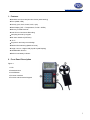
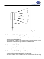
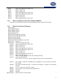
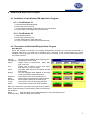
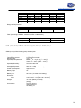
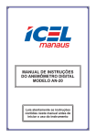
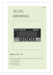
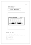
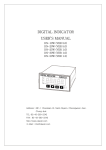
www.pce-industrial-needs.com
Tursdale Technical Services Ltd
Unit N12B
Tursdale Business Park
Co. Durham
DH6 5PG
United Kingdom
Phone: +44 ( 0 ) 191 377 3398
Fax: +44 ( 0 ) 191 377 3357
[email protected]
http://www.industrial-needs.com/
Manual
PCE-007 Air flow meter
[email protected]
1. Features .......................................................................................................................... 3
2. Front Panel Description ................................................................................................. 3
2.1. LCD .................................................................................................................................. 4
3. Operation Instruction ..................................................................................................... 5
3.1. Measurement of Wind Velocity (refer to figure 2) ....................................................... 5
3.2. Measurement of Wind/Air Temperature ........................................................................ 5
3.3. Measurement of Wind/Air Flow (Instant Air Flow) ....................................................... 5
3.4. Measurement of Wind/Air Flow (2/3Vmax Air Flow) .................................................... 6
3.5. Measurement of Wind/Air Flow (Average Air Flow)..................................................... 6
3.6. Holding the Reading....................................................................................................... 6
3.7. Finding the Maximum or Minimum values ................................................................... 6
3.8. To Record One Data (One Shot, Sampling Time = 0) .................................................. 7
3.9. To Record Data Continuously (Sampling Time <> 0) .................................................. 7
3.10.
To Read Data Stored in Memory Sequentially ...................................................... 7
3.11.
To Read Data Stored in Memory Randomly .......................................................... 7
3.12.
To Send Data Out to PC through RS-232C (AVM-07) ........................................... 7
3.13.
The Data Format of 15 Data Sent Out to RS-232................................................... 7
3.14.
Down Load Data to Personal Computer (AVM-07) ............................................... 8
3.15.
Data Format Stored in Memory .............................................................................. 8
4. WindowsTM Application Program ................................................................................ 9
4.1. Installation of the WindowsTM Application Program .................................................. 9
4.1.1. For Windows 3.1 ...................................................................................................... 9
4.1.2. For Windows 95 ....................................................................................................... 9
4.2. Description of WindowsTM Application Program ....................................................... 9
5. Specifications( 23 ± 5° C) ............................................................................................. 13
6. Battery Replacement .................................................................................................... 15
2
[email protected]
1. Features
z Sensitive and Accurate (ultra low friction jewel bearing)
z Flow (CMM, CFM),
z Velocity (m/s, ft/min, knots, km/hr, mph)
z Dual Display (VEL + Temperature, FLOW + AREA)
z Memory of 2000 Records
z One Shot or Continuous Recording
z Sampling time set by keypad
z RS-232C interface (PCE-007)
z °C/ °F
z Ergonomic and easy-to-use design
z Read while measuring (detached vane)
z Large 17mm 3 ½ digits LCD (Liquid Crystal Display)
z Hold/Max/Min function
z Build-in low battery indicator
2. Front Panel Description
Figure 1
1 LCD
2 Detached Vane
3 On/Off Button
4 RS-232C Interface
5 Function and Numerical Keypad
3
[email protected]
2.1. LCD
AVE:
REC:
When method of average is selected by OPTION button for flow measurement, this symbol will
appears.
When MAX/MIN button is pressed twice, this symbol will appear to indicate MIN value of ever
measured value for either velocity or flow is displayed in LCD
This symbol will be displayed together with MAX when 2/3VMax method is selected by
OPTION button in flow measurement.
When MAX/MIN button is pressed once, this symbol will appear to indicate MAX function is
enable.
When VEL/FLOW button (number 4) is pressed, this symbol will appear to indicate
anemometer is measuring wind velocity.
When the read function is enabled to read data stored in the anemometer, this symbol will
appear.
When the anemometer is recording data, this symbol will appear.
RS-232:
ft2:
m2:
°C:
When the RS-232 function is enabled, this symbol will appear.
This symbol is used to indicate free area in square feet when in flow function.
This symbol is used to indicate free area in square meter when in flow function.
This symbol is used indicate temperature in Celsius.
°F:
CFM:
CMM:
x100:
x10:
m/s:
ft/min:
MPH:
Km/h:
This symbol is used to indicate temperature in Fahrenheit.
MIN:
2/3V:
MAX:
VEL:
READ:
This symbol is used to indicate unit in cubic feet per minute.
This symbol is used to indicate unit in cubic meter per minute.
This symbol is to used indicate the actual value is the value display in LCD multiplied by 100.
This symbol is to used indicate the actual value is the value display in LCD multiplied by 10.
This symbol is to used indicate the unit is in meters per second.
This symbol is to used indicate the unit is in feet per minute.
This symbol is to used indicate the unit is in miles per hour.
This symbol is to used indicate the unit is in kilometers per second.
4
[email protected]
3. Operation Instruction
Figure 2
3.1. Measurement of Wind Velocity (refer to figure 2)
1. Press the on/off button to turn on the anemometer.
2. Select anemometer function by pressing the VEL/FLOW button (number 4). VEL symbol will appear
in LCD.
3. Press the unit button (number 3) to select desired unit.
4. Determine the approximate wind direction.
5. Hold the anemometer so that the air flow will pass through the vane from the back to the front (the
back: where the mounting nut is; the front: where engraving of ANEMOMETER is).
6. Wait for 2 seconds for a stabilized reading
7. For more accurate results, try to keep the axis of the vane within 20° of the wind direction.
3.2. Measurement of Wind/Air Temperature
1.
2.
3.
4.
When the meter is measuring wind velocity, the temperature of wind is measured at the same time.
Select °C or °F by pressing °C/°F button (number 6).
Let the wind pass through the vane ( A thermocouple is built into the center of the vane).
Read the temperature reading from LCD.
3.3. Measurement of Wind/Air Flow (Instant Air Flow)
1.
2.
3.
4.
Press the on/off button to turn on the anemometer.
Press the VEL/FLOW button (number 4) to select FLOW function. FLOW symbol will appear in LCD.
Press the unit button (number 3) to select the desired unit (CFM or CMM).
The previous stored free area will be displayed in upper LCD. To enter new free area, press AREA
5
[email protected]
(number 0) button. The lower four digits will become blank, and anemometer wait for users to enter.
5. Press the OPTION button several times until none of AVE or 2/3VMAX is shown in LCD.
6. Users enter free area by pressing the numerical keypad. After free area is entered, press ENTER
button to end. The anemometer will also automatically exit entering if all 4 digits are entered.
7. Determine the approximate wind direction.
8. Hold the anemometer so that the air flow will pass through the vane from the back to the front (the
back: where the mounting nut is; the front: where engraving of ANEMOMETER is).
9. Wait for 2 seconds for a stabilized reading. The flow value equals velocity time’s free area.
FLOW = VELOCITY ´(FREE AREA)
10.
For more accurate results, try to keep the axis of the vane within 20° of the wind direction.
3.4. Measurement of Wind/Air Flow (2/3Vmax Air Flow)
1. Press the on/off button to turn on the anemometer.
2. Select anemometer function by pressing the VEL/FLOW button (number 4). FLOW symbol will appear
in LCD.
3. Select the desired unit (CFM or CMM) by pressing the unit button (number 3).
4. The previous stored free area will be displayed in upper LCD. To enter new free area, press AREA
(number 0) button. The lower four digits will become blank, and anemometer wait for users to enter.
5. Press the OPTION button to select 2/3VMAX method.
6. Users enter free area by pressing the numerical keypad. After free area is entered, press ENTER
button to end. The anemometer will also automatically exit entering if all 4 digits are entered.
7. Determine the approximate wind direction.
8. Move around the center of free area to measure the maximum velocity of wind velocity. The
anemometer will record the maximum value and use it to calculate the wind flow.
9. For more accurate results, try to keep the axis of the vane within 20° of the wind direction.
3.5. Measurement of Wind/Air Flow (Average Air Flow)
1. Press the on/off button to turn on the anemometer.
2. Select anemometer function by pressing the VEL/FLOW button (number 4). FLOW symbol will appear
in LCD.
3. Select the desired unit (CFM or CMM) by press the unit button (number 3).
4. The previous stored free area will be displayed in upper LCD. To enter new free area, press AREA
(number 0) button. The lower four digits will become blank, and anemometer wait for users to enter.
5. Press the OPTION button to select AVE method.
6. Users enter free area by pressing the numerical keypad. After free area is entered, press ENTER
button to end. The anemometer will also automatically exit entering if all 4 digits are entered.
7. Press the START button (dot) to clear the upper LCD to zero.
8. Determine the approximate wind direction.
9. Select measuring point in the free area. Once a point is selected, press the NEXT button (dot) to
average the wind flow. The value in the upper LCD will increment by one to indicate how many points
have been averaged. The maximum number of points is 12.
10. For more accurate results, try to keep the axis of the vane within 20° of the wind direction.
3.6. Holding the Reading
Press the hold button to hold the reading of values in LCD.
3.7. Finding the Maximum or Minimum values
Press the MAX/MIN button to record the maximum or minimum values of wind velocity and temperature
or flow.
6
[email protected]
3.8. To Record One Data (One Shot, Sampling Time = 0)
1. Set the sampling time to 0 by pressing the SAMPLE button (number 0) in the VEL mode (measuring
velocity of wind). The previous stored sampling time will be displayed in upper LCD.
2. Enter number 0 and press ENTER button.
3. Every time REC button is pressed, the data in LCD is stored in memory (the data is always kept even
battery is removed later.)
3.9. To Record Data Continuously (Sampling Time <> 0)
1. Set the sampling time to desired value (1 to 240) by pressing the SAMPLE button (number 0) in the VEL
mode (measuring velocity of wind). The previous stored sampling time will be displayed in upper LCD.
2. Enter desired number and press ENTER button.
3. Once the REC button (number 9) is pressed, the data in LCD is stored continuously in memory at the
specified sampling time. (the data is always kept even battery is removed later.). The REC symbol will be
shown in LCD to indicate the status of recording. Maximum number of records is 2000.
4. To stop recording, press the REC button (number 9 ) again to stop recording. If users turn the power off
without pressing the REC button (number 9), the data is lost. Because the information of last record is
not stored. But if all 2000 records are stored, anemometer will stop recording and store the information of
last record in memory.
3.10.
To Read Data Stored in Memory Sequentially
1. Press the READ button (number 7) to read data stored in memory sequentially.
2. The RECORD NUMBER will be displayed in the upper LCD before the data is displayed. The data will
roll over to the first record if the last record is read.
3. To exit READ mode, press RESET button (number 8).
3.11.
To Read Data Stored in Memory Randomly
1. Once anemometer is in READ mode, users can still read a random record in memory.
2. Press SAMPLE button (number 0). and enter the record number (The anemometer is already in READ
mode).
3. Press the READ button (number 7) then the desired record will be displayed in LCD.
4. To exit READ mode, press RESET button (number 8).
3.12.
To Send Data Out to PC through RS-232C (AVM-07)
1. Holding the RS-232 button (number 1) while turning power on will enable RS-232 function. RS-232
symbol will be shown in LCD.
2. 15 bytes of data will be sent out to RS-232C port every one second.
Note: The RS-232 function will be automatically disabled, if continuously data recording is enabled.
3.13.
Byte1:
Byte2:
Byte3:
Byte4:
Byte5:
Byte6:
Byte7:
The Data Format of 15 Data Sent Out to RS-232
0D (hex)
bit4: Velocity OL, bit5: Area OL, bit6: temperature OL.
0: m/s, 1: ft/min, 2: knots, 3:km/hr, 4:MPH
bit2: MAX, bit3: MIN, bit4:0-VEL, 1:FLOW, bit5: 0-Degree C, 1-Degree F, bit7: RS-232
enabled.
bit0: 0-CMM, 1-CFC, bit3: Low Battery, bit4: temperature -OL, bit5: AVE, bit6: 2/3Vmax,
bit7: Instant
Lower LCD decimal point.
bit0: x100, bit1: x10, bit2: x1, bit3: dp1 (right most), bit4: dp2, bit4: dp3 (left most).
Upper LCD decimal point
bit2: x1, bit3: dp1 (right most), bit4: dp2, bit5: dp3 (left most).
7
[email protected]
Byte8:
Byte9:
Byte10:
Byte11:
Byte12:
Byte13:
Byte14:
Byte15:
3.14.
Digit 3 (most significant) in upper LCD.
Digit 2 in upper LCD.
Digit 1 in upper LCD.
Digit 0 (least significant) in upper LCD.
Digit 3 (most significant) in lower LCD.
Digit 2 in lower LCD.
Digit 1 in lower LCD.
Digit 0 (least significant) in lower LCD.
Down Load Data to Personal Computer (AVM-07)
Press the D. LOAD button (number 5) to send all the data stored in memory to RS-232 port.
3.15.
Data Format Stored in Memory
Byte0:0D (hex)
Byte1:Calibration Data 0
Byte2:Calibration Data 1
Byte3:Calibration Data 2
Byte4:Sampling Time
Byte5:Last Record Number (low byte)
Byte6:Last Record Number (high byte)
Byte7:Free Area (low byte)
Byte8:Free Area (high byte)
Byte9:Decimal point of area(refer to byte 778)
Byte10-768
Reserved
Byte769-784
Record 1(16 bytes per record)
Byte769:
Digit 0 (least significant) in lower LCD.
Byte770:
Digit 1 in lower LCD.
Byte771:
Digit 2 in lower LCD.
Byte772:
Digit 3 (most significant) in lower LCD.
Byte773:
Digit 0 (least significant) in upper LCD.
Byte774:
Digit 1 in upper LCD.
Byte775:
Digit 2 in upper LCD.
Byte776:
Digit 3 (most significant) in upper LCD.
Byte777:
Upper LCD decimal point
bit2: x1, bit3: dp1 (right most), bit4: dp2, bit5: dp3 (left most).
Byte778:
Lower LCD decimal point.
bit0: x100, bit1: x10, bit2: x1, bit3: dp1 (right most), bit4: dp2, bit4: dp3 (left most).
Byte779:
Byte780:
Byte781:
Byte782:
Byte783:
Byte784:
Byte785-32768
bit0: 0-CMM, 1-CFM, bit3: Low Battery, bit4: temperature -OL, bit5: AVE, bit6: 2/3Vmax,
bit7: Instant
bit2: MAX, bit3: MIN, bit4:0-VEL, 1:FLOW, bit5: 0-Degree C, 1-Degree F, bit7: RS-232
enabled.
0: m/s, 1: ft/min, 2: knots, 3:km/hr, 4:MPH
bit4: Velocity OL, bit5: Area OL, bit6: temperature OL.
Not used
Not used
Record number 2 to Record 2000
8
[email protected]
4. WindowsTM Application Program
4.1. Installation of the WindowsTM Application Program
4.1.1. For Windows 3.1
A. Start MicrosoftTM WindowsTM
B. Insert disk in drive A (or B)
C. From Program Manager, select File menu and choose Run
D. Type a:\setup (or b:\setup) and press Enter key
4.1.2. For Windows 95
A. Start WindowsTM 95
B. Insert disk in drive A (or B)
C. Press START button, then select Run
D. Type in a:\setup (or b:\setup) and press Enter key
4.2. Description of WindowsTM Application Program
Main Window:
When the program is executed, the program automatically searches for connected anemometer or
available serial port. If no serial port is available, then a message of "No communication port" will be
displayed, and the program exits. Once communication port is setup, a main window will be displayed on
the screen as below:
Sample:
The value under SAMPLE is the sampling time.
Temperature: Temperature of air or wind.
Option:
Display option of anemometer. MAX, MIN,
AVE, 2/3V max.
Unit:
Display units of velocity or flow (m/s, ft/min,
knot, mph, kmh, CFM, or CMM)
Value:
The value under VALUE is the reading from the
anemometer.
Range:
The text displayed under RANGE is the range
of the unit selected at the anemometer.
Minimum:
The minimum value ever recorded by PC.
Reset:
Clear minimum and maximum value recorded.
Maximum:
The maximum value ever recorded by PC.
Lower:
The minimum value of the range specified.
Upper:
The maximum value of the range specified.
File: If you select File, a pull down menu will show six options:
Name, Start Recording, End Recording, VIEW, Plot Data from
File, and Exit.
Name:
Enter file name to store data displayed in LCD at specified interval.
Start Recording: Start recording when selected
9
[email protected]
End Recording:
End recording when selected.
VIEW FILE:
If the View option under FILE in the Main Window is selected, a view window will be shown as above, and the
users can review your ASCII data file. If a printer is connected to the PC, users can print out content
selectively.
File: Open user’s data file by selecting this menu. Users will be asked to enter file name. After the name
being entered, program will read in one block of data. Number of records in one block depends on the
memory size of PC. The bigger memory, the more records in one block.
Blocks Read:
Indicate how many blocks of records have been read.
Records Read:
Indicate how many records have been read.
Chars./Record:
Indicate how many characters in one record.
Current Block:
Indicate the current block number being reviewed.
Selected:
Indicate the current record number being selected.
Plotting Data from File
If the "Plot Data from File" option under FILE is selected in the Main Window, a Plot Window will be shown, and
the users can plot curve of your data file. If a printer is connected, users can print out the curve.
File:
Open the file to plot data from
Select:
Select one of the items Velocity, Temperature, Flow, or Area to plot
Scale:
Set the scale of Y-axis.
X Label: Users can select sequence number (1,2,3,4,...) or time (12:00:01, 12:00:05, ...) as X-axis label.
Title:
Enter the title for X-axis, Y-axis, or Graph.
Grid:
Draw Horizontal, Vertical grids or both.
Zoom:
Zoom into the graph. The zoom size is limited to 3600 points.
Statis:
Statistics. This function allows users to plot average value,
10
[email protected]
Standard deviation, best fit over the curve. This function is valid only when they are less than 3600 data. If
there are more than 3600 data, STATIS will be disabled.
Clear: Clear the graphic screen.
Print: Print out the curve if a printer is connected to PC.
DISPLAY: DISPLAY menu has four options: DIGITAL, ANALOG, LIST, and GRAPHIC.
DIGITAL:
If this option is selected or CTRL+D are pressed, a window, which emulates multimeter's LCD display, shall
appear on the screen.
ANALOG:
11
[email protected]
If this option is selected or CTRL+A is pressed, a window, which emulates an analog meter, shall appear on
the screen.
LIST:
If this option is selected or CTRL+L is pressed, a window, which lists the date, function, range, and value every
sampling, shall appear on the screen.
GRAPHIC:
If this option is selected or CTRL+G is pressed, a window, which emulates strip chart recorder, shall appear on
the screen. The graphic window has two menus, PRINT and SCALE. Select the PRINT menu, the graphics will
be printed through any printer connected to the PC. The SCALE menu allows user to set the minimum and
maximum value for the Y (vertical) axis.
Option: If you select Option, a pull down menu will show three options: Sample Rate, Baud Rate.
Upper Limit:
Enter upper limit. If upper limit is exceeded, a OVER message will be displayed in screen.
Lower Limit:
Enter lower limit. If displayed value is less than lower limit, a UNDER message will be
displayed in screen.
Graphic Mode: Select way of display in the graphic windows. Dot or BAR.
Sample Rate: Select this option to enter PC sampling time, or click at the SAMPLE on screen to enter
sampling time.
Baud Rate:
9600.
12
[email protected]
Datalogger:
CALIBRATION DATA:
They are the calibration data stored in memory of anemometer. They are used when returned for repair.
DATALOGGER SETUP:
They are the sampling time and total record numbers stored in anemometer.
Time:
This time will be used as initial time when converting data. This is a value entered by users.
Down Load:
When this button is pressed, program will ask the users to enter file name. After file name is entered, users
have 10 seconds to press the key of D. LOAD (number 5) of anemometer.
When the D. LOAD key of anemometer is pressed, all the data stored in the memory of anemometer will be
sent to PC. Program will convert all the coded data to a ASCII file under the name entered by users.
5. Specifications( 23 ± 5° C)
Range of Wind Velocity:
Units
Range
m/s
ft/min
knots
Km/hr
mph
0.0 - 45.0
0 - 8800
0.0 - 88.0
0.0 - 140.0
0.0 - 100.0
m/s: meter per second
knots: nautical miles per hour
mph: miles per hour
Resolutio
n
0.01
2
0.02
0.04
0.02
Threshold
Accuracy
0.3
60
0.6
1.0
0.7
±3% ± 0.1
±3% ± 20
±3% ± 0.2
±3% ± 0.4
±3% ± 0.2
ft/min: feet per minute
Km/hr: kilometers per hour
Unit Conversion table:
13
[email protected]
1 m/s
1 ft/min
1 knot
1 Km/hr
1 mph
m/s
1
0.00508
0.5144
0.2778
0.4464
ft/min
196.87
1
101.27
54.69
87.89
knots
1.944
0.00987
1
0.54
0.8679
Km/hr
3.60
0.01829
1.8519
1
1.6071
mph
2.24
0.01138
1.1523
0.6222
1
Range of Temperature:
Range
0 - 45.0
32.0 - 113.0
°C
°F
Resolution
0.2
0.36
Accuracy
±1.0
±1.8
Flow (Auto-range, CMM: 0 - 45.00 m/s, CFM: 0 -8800 ft/min)
CFM (ft3/min)
CMM(m3/min)
Range
0 - 999900
0 - 999900
Resolution
0.001 - 100
0.001 - 100
Area
0.001- 9999
0.001- 9999
CFM (ft³/min)=Wind Velocity(ft/min)x Area(ft²)
CMM (m³/min)=Wind Velocity(m/s)x Area(m²)x60
Bearing:
Temperature sensor:
Mounting Nut:
Operating Temperature:
Sapphire jewel bearing
K-type thermocouple
1/4" x 20
Meter: 0 °C ~ 50°C (32 °F ~ 122°F)
Vane: 0°C ~ 60°C (32 °F ~ 140°F)
Operating Humidity:
Operating Pressure:
Storage Temperature:
Less than 80% RH
500 mB ~ 2 Bar
-40°C ~ 60°C (-40°F ~ 140°F)
Approx. 3 mA
9V
50 hours ( for 300mA-hrs battery)
Power Consumption:
Battery Type:
Battery Life:
Dimension:
Meter
Vane
Weight:
Accessories:
3.46"x 6.61"x 1.03"(88x 168 x 26.2mm)
2.60"x 5.22"x 1.15"(66x 132 x 29.2mm)
12.34oz. (battery included)
(350g)
Carrying case x 1
Users manual x 1
9V Battery x 1
14
[email protected]
6. Battery Replacement
When the low battery symbol is displayed on LCD, follow the following procedures to replace the battery.
1. Turn off the anemometer by pushing the On/Off button.
2. Remove the screw of the battery compartment cover and remove the battery compartment cover.
3. Replace the old 9V battery with a new 9V battery.
4. Replace the battery compartment cover and fasten the screw.
In this direction will find a vision of the measurement technique:
http://www.industrial-needs.com/measuring-instruments.htm
NOTE: "This instrument doesn’t have ATEX protection, so it should not be used in potentially explosive
atmospheres (powder, flammable gases)."
15