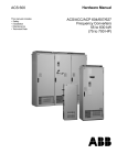
1
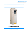
ENGLISH
NO. 148 383 02
2001-08-20
Fan Inverter
INSTRUCTION MANUAL
Fan Inverter
List of contents
Declaration of conformity
Safety
Technical data
System Description
The Fan
Installation
The pressure controller
Programming
Starting up
Supervision
Reading operating data
Locking
Accessories
Spare parts
Parameter list
Mains wiring diagram
Control wiring diagram, general
Control wiring diagram, FILTERMAX
page
3
4
5
6
6
7
11
11
12
13
13
13
14
14
15
16
17
18
Valid from Contr. No 01050-0
2
Fan Inverter
This product is designed to meet the requirements of the relevant EC directives. To maintain this status
all installation, repair and maintenance work must be carried out by qualified personnel using only
original spare parts. Contact your nearest authorised dealer or
AB Ph. Nederman & Co. for advice on technical service or if you require spare parts.
Declaration of conformity
We, AB Ph. Nederman & Co., declare under our sole responsibility that the Nederman product:
Fan Inverter
Part. No 14511837, 14511937, 14512037, 14512137, 14512237,
14512637,14515137,14515237,14515337,14515437
to which this declaration relates, are in conformity with
the following standards or other normative documents:
EN 61800-3, EN 50 082-2, EN 60 439-1
following the provisions of Directive
89/336/EEC, 93/68/EEC, 73/23/EEC
AB Ph. Nederman & Co.
Sydhamnsgatan 2
S-252 28 Helsingborg Sweden
2001-08-10
________________________________
Alf Jonasson, Product Manager
3
Fan Inverter
SAFETY
Warning!
Only a competent electrician may install the Fan Inverter.
Warning!
Dangerous voltages are present when mains supply is connected.
Wait at least 5 minutes after disconnecting the supply before
removing the cover. Measure the voltage at DC terminals (Uc+ ,
Uc-) before servicing the unit. See E.1
Warning!
Even when the motor is stopped there are dangerous voltages
present at Power Circuit terminals U1, V1 and W1 and also
between U2, V2, W2 and U c+ and U c- .
Warning!
Even when the Fan Inverter is powered down, there may be
dangerous external voltages at relay terminals RO1A, RO1B,
RO1C, RO2A, RO2B, RO2C.
Warning!
Never attempt to repair a broken unit; contact the supplier..
Warning!
Fan Inverter will start up automatically after an input voltage
interruption if the external run command is on.
Warning!
When the control terminals of two or more Fan Inverter units are
connected in parallel, the auxiliary voltage for these control
connections must be taken form a single source, which can either
be one of the units or an external supply.
Warning!
The heat sink may reach a high temperature (see S, Table 111)
Warning!
If the supply network is floating (IT network) do not use RFI filter.
The mains becomes connected to earth through the filter
capacitors. In floating networks this may cause danger or damage
the unit. See H.1
Note! For more technical information, contact the supplier.
1
ABB User's Manual is attached with the delivery.
4
TECHNICAL DATA
Fan Inverter
Part. No
Power
Type
Input
Protection class
Control voltage
Pressure transducer
Frame size
RFI-filter
Input current I1NSQ
Output current I2NSQ
Line fuse*
Supply to external
equipment
Dimension H x B x D
Weight with RFI-filter
kW
ABB ACS 401
kPa
ACS401A
A
A
at
400V 3~+N
mm
3
14511837
3
-004-3-5
4
5,5
7,5
11
15
18.5
22
30
37
14511937 14512037 14512137 14512237 14512637 14515137
14515237 14515337 14515437
4
5,5
7,5
11
15
18,5
22
30
37
-005-3-5
-006-3-5
-009-3-5
-011-3-5
-016-3-5
-020-3-5
-025-3-5
-030-3-5
-041-3-5
380V - 480V ±10% 48 - 63 Hz, 3~ (+N at 400V to receive 230V to extern equipment)
IP 54, No conductive dust allowed, see "A" in ABB User's Manual
24 V DC, 250 mA
max 3,0
R1
R2
R3
R4
-IF11-3
-IF21-3
-IF31-3
-IF41-3
6,2
8,3
11,1
14,8
21,5
29
35
41
56
68
6,6
8,8
11,6
15,3
23
30
38
44
59
72
10 (16)
10 (16)
16 (25)
16 (25)
25 (35)
35 (50)
50
50
63
80
230 V AC max 6 A,
accessories 12372075 and 12371984 have to be connected
450 x 215 x 300,
550x215x315,
642 x 257 x 280 **
742 x 257 x 312 **
kg
with RFI filter
with RFI filter
10
14
22,3**
32,3**
NCF
NCF
NCF
NCF
160/25
80/25
120/25
50/25
160/25***
80/15
120/25***
80/25***
120/15
* Fuse type: UL class CC or T. For non-UL installations IEC269 gG. When additional fuse installed, accessory 12371984, use value between brackets.
** Dimensions without RFI filter, to be mount separately: IF31: 500 x 170 x 80 , 8 kg; IF41: 550 x 200 x 80, 11,5 kg.
*** In many applications the maximum fan power outtake is not required and gives the possibility to use one size smaller Fan Inverter.
Note! Use 60C rated power cable (75C if ambient temperature exceeds 45C).
Note! The maintenance/safety switch, if installed, can be used only as a safety device. Do not operate (close) the switch when the Fan Inverter is running. The signal contact in the
switch have to be connected to “run enable”, terminal X1 8 - 14, or void warranty.
Suitable Nederman
Fan
400V
50Hz /
460V
60Hz
N29
N40
NCF 30/15
NCF 30/25
NCF 40/25
Fan Inverter is suitable for use in a circuit capable of delivering not more than 65 kA rms symmetrical amperes, 480 V maximum.
5
Fan Inverter
SYSTEM DESCRIPTION
The Nederman Fan Inverter is a frequency controller for Nederman NCF fans.
Equipped with a pressure transducer and the built-in PID controller it can maintain a constant negative
pressure in an extraction system and by this almost a constant airflow in the extraction devices. The fan
capacity is regulated to the actual demand of the airflow, depending on the number of extraction points
in use at the same time.
The benefit of using the inverter is primarily in the conservation of energy. Achieved from reduced
running costs, lower heat loss to atmosphere and reduced noise levels. All of these points relate to the
general day to day usage of the system as the demand increases/decreases.
The inverters integral control transducer senses the system pressure taken from the farthest point in the
duct system or at the extraction point which offers most pressure drop.
The system can be started with the 1/0 button on the control panel, in local mode "LOC" or by an
optional potential free remote contact in the remote mode "REM" which is recommended. The system
has more protection abilities in “REM”-mode.
The remote start is used when the Fan Inverter is combined with FILTERMAX or a Fan Timer or a
remote start switch. In combination with extractor arms with spotlight the automatic damper or a voltage
separation relay have to be used to get the potential free contact.
When connected to FILTERMAX and in REM-mode, the Fan Inverter is the "slave" with the FILTERMAX
used as the “master”. The start button, on FILTERMAX control box, then starts the system. An other
possibility is to start from a remote
potential free contact or a Fan Timer
1
connected to FILTERMAX control box.
0,9
0,8
THE FAN
dpf/dpn
When a fan is frequency controlled a
constant pressure can be achieved in
the whole working range of the fan, up to
the fan maximum frequency.
Working
range
0,7
0,5
f =40 Hz
0,4
In many applications the maximum fan
power outtake is not required and gives
the possibility to use one size smaller Fan
Inverter, for NCF 80/25, 120/25 and
160/25.
By estimation of the maximum fan power
consumption for the actual working range
in your application, using NedQuote as an
aid, a Fan Inverter with at least the same
power can be selected.
f =30 Hz
0,2
f =20 Hz
0,1
0
0
0,2
0,4
0,6
0,8
1
Qf/Qn
Diagram 1. Fan curve changed by frequency
2
1,8
1,6
1,4
Pf/Pn
For Nederman fans the maximum
frequency is normally the fan nominal
frequency, i.e. 50 or 60 Hz. Above these
frequencies too much mechanical stress is
imposed on the impeller which could be
detrimental with failure occurring.
Constant
pressure
fan curve
0,6
0,3
The power consumed follows
proportionally as a cube, i.e. as the fan
R.P.M. is reduced by half so the power is
th
reduced to an 1/8 , see diagram 2.
Although the cooling effect from the
motor cooling fan is reduced when the
R.P.M. is decreased, the power
consumption is reduced even more and
there is no risk of overheating by
reducing the frequency.
f =50 Hz
1,2
1
0,8
Working
range
0,6
0,4
0,2
0
0
10
20
30
40
50
60
70
80
Frequency / Hz
Diagram 2. Relative power consumption versus
frequency, (nominal frequency 50 Hz)
6
7
Fan Inverter
INSTALLATION
Study the Safety instructions on page 4. Study the installation instructions given in this
document and in the ACS 400 user’s manual and the ACS 400 EMC instructions carefully before
proceeding.
Failure to observe the warnings and instructions given may cause a malfunction or personal
hazard.
Note the need of shielded cables for the motor and control.
Dimension the cables and fuses in accordance with the Inverter and motor current.
Always pay attention to local legislation when sizing the cables and fuses. See table “Technical data” on
page 5 for Line fuse rating
th
A main switch shall be installed on the power supply for the Fan Inverter. A 4 pole for neutral and a
fuse is needed if the same main switch, (with supply 400V 3Ph +N), supplies FILTERMAX or other 230
V single-phase equipment. See “Mains interconnection diagram”.
If the power supply network also supplies buildings used for domestic purposes the Fan Inverter has to
be equipped with a RFI filter. This is not needed if the system has an intermediate transformer but is
recommended to avoid problems with sensitive equipment.
The Fan Inverter is delivered with RFI filter as standard.
If the supply network is floating (IT network) do not use RFI filter. The mains becomes connected to
earth through the filter capacitors. In floating networks this may cause danger or damage the unit.
1
See H .
Due to a leak current to ground from the RFI filter at power on, approx. 100 mA, the Fan Inverter can not
be connected to a supply with GFI (Ground Fault Interrupter) for a lower leakage current rate.
Up to Fan Inverter 11 the RFI filter ACS400-IFX1-3 is first to be mounted on the wall and then the unit is
mounted upon the RFI filter. For Fan Inverter 15 the RFI filter is mounted separately. With terminal cover
it has an IP54 protection class. For RFI-filter ACS400-IF41-3 (>= 22kW) a choke, ACS-CHK-A included,
must be mounted around the motor cable, maximum 0,5 m from the unit.
If the fan is located in another location then the main switch, a maintenance switch with signal contact
should be used. The signal contact has to be connected to “run enable, terminal X1 8-14, or this voids
the warranty. Due to the RFI emission risk the switch has to be of a RFI protected type and the cable
shield must be connected. Use cable glands at the motor for shielded cables.
1
ABB User instruction is attached with the delivery.
7
Fan Inverter
Fig 1 Installation Fan Inverter
Supply: 400V 3/N, PE, 50 Hz
Fuse 6 A , connected
to output side from
main switch.
Accessory
Main switch
for the System
3 +N (separate block)
Accessory.
Voltage separation
relay, Has to be
installed if the Fan
Inverter is controlled
from the switch on the
hood,(alt. autom.
damper) Accessory.
Fan Timer
For automatic start and
stop. Accessory
Recommended!
Fan Inverter mounted
on the RFI filter, (up to
11 kW)
External warning label,
can be placed by you.
(English label not
supplied, already placed
inside, see fig 2)
Shielded Motor cable
(choke, only for RFIfilter ACS 400-IF41-3)
Keep cables at >= 0,2 m
distance to the inverter
and motor cable
Shielded
Motor cable
Maintenance
switch
Do not forget to
connect the
signal contact
with shielded
cable to the Fan
Inverter
8
Fan Inverter
Fig 2
Fan Inverter up to 11 kW
Fig 3 Fan Inverter from 15 kW
N.B The pressure transducer have to be mount
exactly as shown on the pictures. The electrical
terminal on the transducer have to be positioned
over the two relays to have enough space under
the cover.
The flexible hose shall be mounted on the outer,
transparent, fitting on the transducer. Do not
remove the red plugs. The other end is connected
to a fitting in one of the upper holes in the rubber
flange. The plastic hose 6/4 mm is then to be
connected to the pressure tap in the duct, see fig 4
and 5.
Fig. 4 Pressure tap, hole diam. 16 mm in duct
wall. Holder fit 160 – 315 mm duct.
Connect the control cables to terminal X1
according to circuit diagram fig. 6 see also "Control
interconnection diagram, general” and "Control
interconnection diagram, FILTERMAX " .
The control cable screen shall be connected to X1 - 1 "SCR".
A new warning label in the language of your choice can be attached on the unit cover. fig.1 or inside,
instead of the English label, fig 2 and 3.
910
Fan Inverter
Pressure tap in duct at
the point of maximum
resistance
T-piece in the middle of
two pressure taps
providing an average
pressure drop
Fan Inverter with
pressure transducer
Analogue input has to be set
to 0-10 V according to figure
U/I jumper J1 or DIP switch
Fig 5 Pressure measurement
ON >
ON >
Optional
remote start
contact
If maintenance switch installed,
remove link and connect signal
contact to 8-14, see wiring diagram,
general
Connect hose on
outer connector
Ferrite on
transducer
cable
Fig 6. Basic connection, see also
control wiring diagram, general and
FILTERMAX
Pressure
transducer
10
Fan Inverter
THE PRESSURE CONTROLLER
The pressure transducer range is 0 - 3 kPa, the output is 0,5 – 4,5 V and connected to AI2 (analogue
input 2) . A pressure tap with filter shall be inserted in the duct at a location were you expect the
greatest pressure drop to occur, normally at the most distant extraction unit. If the duct system is
branched, you could use pressure taps in the end of the branches and connect them together, with
equal length of hose before you connect the pressure signal to the Fan Inverter. In this way you get an
"average" pressure value.
The PID controller senses the actual pressure value, represented in the display as kPa and adjusts the
speed of the fan in order to keep the pressure in accordance with the reference value. The reference
value is set by pressing the up or down arrow keys on the keypad. The reference value is in a "%" of the
pressure transducer range, in the upper right of the display. 30% reference value corresponds to 0,30 x
3 kPa = 0,90 kPa. Set the reference to a value that gives you the correct airflow from the extraction
points.
PROGRAMMING
Fan Inverter is pre-programmed.
At delivery the basic programming is stored in the Fan Inverter.
A copy is also stored in the Control Panel memory as a backup.
The basic parameters for the actual motor have to be set prior to use.
Get familiar with the ACS-PAN-A Control Panel by reading the ACSPAN-A part in the Programming chapter in the ABB User's Manual.
For the programming and test run the Fan Inverter have to be in Local
mode, LOC. To be able to see all parameters the “FULL MENU” has to
be selected. Press the MENU-button and arrow-buttons so you get
"FULL/SHORT MENU then press and hold ENTER until you get
“∗”visible in the display.
Now you move with the arrow-buttons to group 99 START-UP DATA,
press ENTER and you get access to the parameters. Please set the
motor parameters and language of your choice, see table below.
99 START-UP DATA
MENU
LOC
*
Fig 7. Control Panel
When changing a parameter press ENTER and you will get a line under
the parameter value, change the value with the arrow-buttons and
confirm by pressing ENTER again. To exit press the MENU-button.
Note Do not change any other parameters than listed in the table below as this may render the inverter
useless. Please contact Nederman direct if this is needed.
Code
9901
9905
9906
9907
9908
9909
9910
1003
1406
1602
1605
3202
3203
4019
4020
Name
LANGUAGE
MOTOR NOM. VOLT
MOTOR NOM. CURR
MOTOR NOM. FREQ.
MOTOR NOM. SPEED
MOTOR NOM. POWER
MOTOR COS PHI
DIRECTION
RELAY 2 OFF DELAY
PARAMETER LOCK
LOCAL LOCK
SUPERV 1 LIM LOW
SUPERV 1 LIM HI
SET POINT SEL
INTERNAL SETPNT
Parameter alphanumeric
ENGLISH (UK) or your choice
According to motor plate
According to motor plate *
According to motor plate
According to motor plate
According to motor plate
According to motor plate
FORWARD / REVERSE
15 s
Alarm delay time
LOCKED / OPEN
OPEN / LOCKED (only in REM mode)
25%
Alarm level
28%
OK level
EXTERNAL (arrow buttons)/(INTERNAL)
Please note used values
According to your system (preset 40%)
* When using oversized motor rating, set the value = the maximum current (I2NSQ) for the Fan Inverter:
Fan Inverter 7.5 together with NCF 80/25 11 kW 9906 = 15.3 A and Fan Inverter 11 together with NCF
120/25 15 kW 9906 = 23 A FanInverter 15 together with NCF 160/25 18,5 kW 9906 = 30 A.
Note. At acceleration and deceleration a warning for overcurrent and overvoltage may occasionally be
visible at the display this is not any fault, we are only using the inverter to its limit
11
12
Fan Inverter
Power P VAR 1
Reference value
100%
Hi 28%
Low 25%
30 %
10
0.900 kPa
Transducer output (V)
Analogue input 2 (V)
Cooresponding value
100% = 10 V
100%
Reference value in % of
transducer range. I.e
30% = 0,900 kPa
Supervision of duct pressure.
Relay 2 close at Hi and open
at Low after delay
2.6 kW
Display
45%
4,5
5%
0
0,5
Actual value P VAR 2
30%
0%
0
0
0,75 0,9
3
Duct underpressure (kPa)
Diagram 3 Pressure signal
STARTING UP
Now it is time to start the fan for the first time.
Set the reference value to 30% by pressing the arrow-button.
In LOC mode start and stop the fan with the 1/0-button to check
the fan rotation. To change the direction you can change the
parameter 1003, FORWARD or REVERSE.
Change to REM if you are going to us the remote start mode.
Check the reference value again, it may have been changed
when changing from LOC to REM.
Start the system with 1/0 button in local mode or by activating the
remote start contact, i.e. FILTERMAX start button. If there is any
damper between the fan and the pressure tap it have to open.
The fan will now accelerate up to a speed creating a 30% =
0.900 kPa system pressure in the duct at the pressure tapping.
Adjust the reference value up or down by using the arrow-buttons
on the panel to achieve the correct extract rate from the hoods etc.
1213
Fan Inverter
SUPERVISION
It is important to have sufficient airflow in the extraction points. Fan Inverter controls the fan capacity to
the actual demand. However the system pressure may not be sufficient i.e. when too many extraction
points is open at the same time, the reference value have been decreased or the hose to the pressure
tap is broken. Integrated in the Fan Inverter there is a possibility to supervise the system pressure, relay
2 is used for this supervision. The relay is ON when the pressure is OK and can be connected to an
external warning system or FILTERMAX control box..
Actual value, 100% = 3 kPa
Reference 30%
28%
Hi 3203
Low 3202 25%
15
0
Relay 2
OK 20-22
Delay
1406
Low 20-21
Diagram 4 Supervision.
The parameters Hi and Low are setpoints for the action of the relay and have to be adjusted according
to the used reference value, in this example the reference is 30 % - 0,9 kPa. The OK-level “Hi” is
somewhat lower 28% - 0,84 kPa. The Alarm level “Low” is set to the lowest acceptable level giving
sufficient airflow in the extraction devices.
The relay is de-energised after a delay time, default 15 s.
When connected to FILTERMAX “Low airflow” -input there is an
additional 60 s delay before a FILTERMAX Service alarm is
activated.
READING OPERATING DATA
When the system is working correctly a reading and noting of operation data (Group 01) is
recommended. For this operation the FULL MENU have to be selected “∗” must be visible in the display.
With the maximum numbers of extractor points open, according to the dimensioning, read and note the
operation data.
The RUN TIME (0114) and the kWh COUNTER (0115) can bet reset, see ABB User's Manual.
Let an electrician measure the mains voltage during operation and note it down.
LOCKING
When completed lock local mode parameter "1605" if only remote is to be used and
finally Lock parameters "1602”. To use panel 1/0 button again unlocking has to be
made in reverse order.
The reference value can still be changed with the arrow buttons. If the reference value
shall not be easily changed the internal reference can be selected before locking, parameter 4019 SET
POINT SEL set to INTERNAL and the reference value set in parameter 4020.
1314
Fan Inverter
ACCESSORIES
Main (Safety/Maintenance) switch 3 pole, max 18,5kW, EMC
14372075
Fuse 6A incl.4th pole (N) to main switch 14372075 for supply 230 V to
external equipment (i.e. FILTERMAX),
14371984
Fan Timer
14372077
Voltage separation relay
12 V AC
24 V AC
Hose 6/4 mm, 100 m
14372148
14372149
14372082
SPARE PARTS
Ordering Instructions
When ordering spare parts always indicate the following:
A. Part No. and Control No. (see Nederman Fan Inverter identification plate)
B. The spare part’s name and number, (see Spare Parts List)
C. Quantity of parts required.
Spare Parts List
Name
1
Frequency control, incl. Cover and Control Panel
2
Control panel
3
Pressure transducer kit
4
RFI-filter
5
Cover
6
Pressure tap kit
1
2
3
4
5
6
1415
Fan Inverter
PARAMETER LIST
Fan Inverter is pre-programmed. At delivery the basic programming is stored in the Fan Inverter.
A copy is also stored in the Control Panel memory as a backup.Additionally is here the complete list of
parameters to be checked/changed after the application macro is selected. To be able to see all
parameters the "FULL MENU" have to be selected, "*" must be visible in the display.
Code
9901
9902
9905
9906
9907
9908
9909
9910
1003
1101
1102
1106
1304
1305
1306
1401
1402
1406
1602
1605
2003
2008
2101
2102
2103
2202
2203
2606
3001
3201
3202
3203
3401
3402
3403
3404
3405
3406
3407
3408
3409
3410
3411
4001
4002
4019
4020
Name
Language
Application makro
Motor nom. volt
Motor nom. curr
Motor nom. freq.
Motor nom. speed
Motor nom. power
Motor cos phi
DIRECTION
KEYPAD REF SEL
EXT1 / EXT2 SEL
EXT REF2 SELECT
MINIMUM AI 2
MAXIMUM AI 2
FILTER AI 2
RELAY OUTPUT 1
RELAY OUTPUT 2
RELAY 2 OFF DELAY
PARAMETER LOCK
LOCAL LOCK
MAX CURRENT
MAXIMUM FREQ
START FUNCTION
STOP FUNCTION
TORQ BOOST CURR
ACCELER TIME 1
DECELER TIME 1
U/F RATIO
AI < MIN FUNCTION
SUPERV 1 PARAM
SUPERV 1 LIM LO
SUPERV 1 LIM HI
DISPLAY SEL
P VAR 1 SEL
P VAR 1 MULTIP
P VAR 1 DIVISOR
P VAR 1 SCALING
P VAR 1 UNIT
P VAR 2 SEL
P VAR 2 MULTIP
P VAR 2 DIVISOR
P VAR 2 SCALING
P VAR 2 UNIT
PID GAIN
PID INTEG TIME
SET POINT SEL
INTERNAL SETPNT
Parameter alphanumeric
ENGLISH (UK) or your choice
PID CTRL
According to motor plate
According to motor plate *
According to motor plate
According to motor plate
According to motor plate
According to motor plate
FORWARD / REVERSE
REF2 (%)
EXT 2
KEYPAD
5%
45 %
1.0 s
READY
SUPERV1 OVER
15 S
Alarm delay time
LOCKED / OPEN
OPEN / LOCKED (only in REM mode)
(I2NSQmax, see user's manual section S)
50 Hz according to fan
FLY + BOOST
COAST
Max
30 s
30 s
SQUARE
NOT SEL
127 (PID) Actual value)
25%
Alarm level
28%
OK level
PROCESS VAR
106 (Power)
1
1
1
KW
127 (PID Actual value)
300
100
3
KPa
1.3
6s
EXTERNAL (arrow buttons) / (INTERNAL)
Used values**
According to your system (preset 40%)
* When using oversized motor rating, set the value = the maximum current (I2NSQ) for the Fan Inverter: Fan Inverter
7.5 together with NCF 80/25 11 kW 9906 = 15.3 A and Fan Inverter 11 together with NCF 120/25 15 kW 9906 =
23 A. Fan Inverter 15 together with NCF 160/25 18,5 kW 9906 = 30 A ( At acceleration and deceleration a warning
for over-current and over-voltage may occasionally be visible at the display ).
Note. At acceleration and deceleration a warning for overcurrent and overvoltage may occasionally be visible at the
display this is not any fault, we are only using the inverter to its limit.
** Note. Do not change grey-marked parameters or other parameters not listed in this table. Contact Nederman if
changes are necessary. Warranty could be invalidated.
1516
Fan Inverter
3/N/PE AC
400/230 V 50 Hz
Line
Load
Fuse 6A
14371984
(with 4th
pole to
14372075)
Fan
Inverter
with RFI
filter
Main switch
14372075, max
18,5 kW (with
optional 4th pole
incl in 14371984
Choke (only >= 22kW)
placed maximum 0.5 m
from inverter
Maintenance
switch 14372075
(max 18,5 kW)
FILTERMAX
Control Box
Mains wiring diagram
16
Fan Inverter
Maintenance switch 14372075, accsessory.
N.B. signal contact has to be connected to X1
8-14 or void warranty. (Leave linked if not
installed)
ON >
ON >
Analogue input has
to be set to 0-10 V
according to figure
U/I jumper J1 or
DIP switch
Fan Timer 14372077 Accessory
NOTE! In installation with FilterMax
shall Fan Timer be connected to
FilterMax directly, please see Fan
Timer instruction manual.
Connect hose on
outer connector
Control wiring diagram, general
17
Maintenance switch 14372075, accsessory. N.B.
signal contact has to be connected to X1 8-14 or void
warranty. (Leave linked if not installed)
Fan Inverter
ON >
ON >
Analogue input has
to be set to 0-10 V
according to figure
U/I jumper J1 or
DIP switch
Connect hose on
outer connector
See FilterMax Instruction manual
Control wiring diagram, FILTERMAX
18
Manufacturer:
AB Ph. Nederman & Co
Sydhamnsgatan 2
SE-252 28 Helsingborg, Sweden
www.nederman.com
Tel.: Int. +46 42 18 87 00
Fax: Int. +46 42 14 79 71
E-mail: [email protected]
Accredited to ISO 9001 and ISO 14001