1
Servicing
I/O Expansion Board (Optional) Replacement
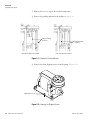
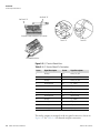
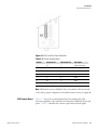
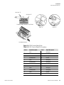
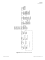
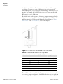
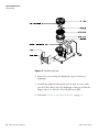
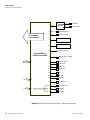
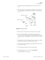
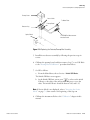
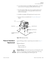
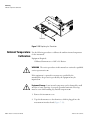
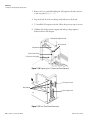
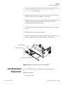
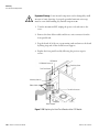
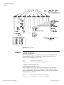
3. Remove the two standoffs holding the I/O expansion board connector
to the rear panel (Figure 7–17).
4. Pop the board off of the mounting studs and remove the board.
5. To install the I/O expansion board, follow the previous steps in reverse.
6. Calibrate the analog current outputs and analog voltage inputs as
defined earlier in this chapter.
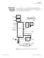
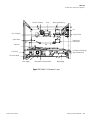
Motherboard Support Bracket
Mounting Studs
Motherboard
Digital Output Board
I/O Expansion Board (Opt)
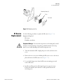
Figure 7–16. Replacing the I/O Expansion Board (Optional)
I/O Expansion Board
Motherboard
Digital Output Board
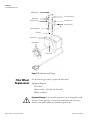
Figure 7–17. Rear Panel Board Connectors
7-36
Model 15i Instruction Manual
Thermo Fisher Scientific