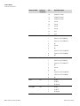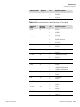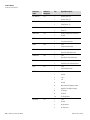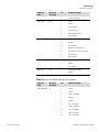
1
Model 55i
Instruction Manual
Direct Methane, Non-Methane
Hydrocarbon Analyzer
Part Number 103962-00
2Aug2012
© 2008 Thermo Fisher Scientific Inc. All rights reserved.
Specifications, terms and pricing are subject to change. Not all products are available in all countries. Please
consult your local sales representative for details.
Thermo Fisher Scientific
Air Quality Instruments
27 Forge Parkway
Franklin, MA 02038
1-508-520-0430
www.thermo.com/aqi
WEEE Compliance
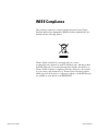
This product is required to comply with the European Union’s Waste
Electrical & Electronic Equipment (WEEE) Directive 2002/96/EC. It is
marked with the following symbol:
Thermo Fisher Scientific has contracted with one or more
recycling/disposal companies in each EU Member State, and this product
should be disposed of or recycled through them. Further information on
Thermo Fisher Scientific’s compliance with these Directives, the recyclers
in your country, and information on Thermo Fisher Scientific products
which may assist the detection of substances subject to the RoHS Directive
are available at: www.thermo.com/WEEERoHS.
Thermo Fisher Scientific
WEEE Compliance
About This Manual
This manual provides information about installing, operating, maintaining,
and servicing the Model 55i analyzer. It also contains important alerts to
ensure safe operation and prevent equipment damage. The manual is
organized into the following chapters and appendices to provide direct
access to specific operation and service information.
Thermo Fisher Scientific
●
Chapter 1 “Introduction” provides an overview of product features,
describes the principles of operation, and lists the specifications.
●
Chapter 2 “Installation” describes how to unpack, setup, and startup
the analyzer.
●
Chapter 3 “Operation” describes the front panel display screens, the
front panel pushbuttons, and the menu-driven firmware.
●
Chapter 4 “Calibration” provides the procedures for calibrating the
analyzer and describes the required equipment.
●
Chapter 5 “Preventive Maintenance” provides maintenance procedures
to ensure reliable and consistent instrument operation.
●
Chapter 6 “Troubleshooting” presents guidelines for diagnosing
analyzer failures, isolating faults, and includes recommended actions for
restoring proper operation.
●
Chapter 7 “Servicing” presents safety alerts for technicians working on
the analyzer, step-by-step instructions for repairing and replacing
components, and a replacement parts list. It also includes contact
information for product support and technical information.
●
Chapter 8 “System Description” describes the function and location of
the system components, provides an overview of the firmware structure,
and includes a description of the system electronics and input/output
connections.
●
Chapter 9 “Optional Equipment” describes the optional equipment
that can be used with this analyzer.
●
Appendix A “Warranty” is a copy of the warranty statement.
●
Appendix B “C-Link Protocol Commands” provides a description of
the C-Link protocol commands that can be used to remotely control an
analyzer using a host device such as a PC or datalogger.
Model 55i Instruction Manual
i
About This Manual
Safety
●
Appendix C “MODBUS Protocol” provides a description of the
MODBUS Protocol Interface and is supported both over RS-232/485
(RTU protocol) as well as TCP/IP over Ethernet.
●
Appendix D “Geysitech (Bayern-Hessen) Protocol” provides a
description of the Geysitech (Bayern-Hessen or BH) Protocol Interface
and is supported both over RS-232/485 as well as TCP/IP over
Ethernet.
●
Appendix E “AK Protocol Commands” provides a description of the
AK protocol commands that can be used to remotely control an
analyzer using a host device such as a PC or datalogger.
Safety
Review the following safety information carefully before using the analyzer.
This manual provides specific information on how to operate the analyzer,
however, if the analyzer is used in a manner not specified by the
manufacturer, the protection provided by the equipment may be impaired.
Safety and Equipment
Damage Alerts
This manual contains important information to alert you to potential safety
hazards and risks of equipment damage. Refer to the following types of
alerts you may see in this manual.
Safety and Equipment Damage Alert Descriptions
Alert
Description
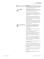
DANGER
A hazard is present that could result in death or serious
personal injury if the warning is ignored. ▲
WARNING
A hazard or unsafe practice could result in serious
personal injury if the warning is ignored. ▲
CAUTION
A hazard or unsafe practice could result in minor to
moderate personal injury if the warning is ignored. ▲
Equipment Damage
A hazard or unsafe practice could result in property
damage if the warning is ignored. ▲
Safety and Equipment Damage Alerts in this Manual
Alert
Description
WARNING
The Model 55i is supplied with a three-wire grounded
power cord. Under no circumstances should this
grounding system be defeated. ▲
If the equipment is operated in a manner not specified by
the manufacturer, the protection provided by the
equipment may be impaired. ▲
ii
Model 55i Instruction Manual
Thermo Fisher Scientific
About This Manual
Safety and Equipment Damage Alerts
Alert
Description
The service procedures in this manual are restricted to
qualified service representatives. ▲
CAUTION
During operation, the sample intake, sample bypass, and
FID exhaust bulkheads are extremely hot. Use caution
when working with a hot instrument. ▲
If the LCD panel breaks, do not let the liquid crystal
contact your skin or clothes. If the liquid crystal contacts
your skin or clothes, wash it off immediately using soap
and water. ▲
Due to the possibility of residual fuel in the detector,
keep your face away from the FID. The ignitor pulse is
clearly visible from a distance when the thermocouple
has been removed. ▲
Avoid contact with the heated oven components. Allow
the oven to cool to room temperature before handling
oven componenets. A small fan directed into the oven
will speed cooling. ▲
Equipment Damage
Do not apply power to the Model 55i until all other
installation procedures have been completed. An
incorrect start-up sequence could damage the
instrument. ▲
Do not attempt to lift the analyzer by the cover or other
external fittings. ▲
Heating the column oven while the carrier gas is not
flowing may damage the column. ▲
Disconnect the serial cable before changing the RS-232
and RS-485 selection to prevent damage to any
equipment that the analyzer is currently connected to.
▲
Some internal components can be damaged by small
amounts of static electricity. A properly grounded
antistatic wrist strap must be worn while handling any
internal component. ▲
Do not use solvents or other cleaning products to clean
the outside case. ▲
Do not disassemble the valve unless the system
malfunction is definitely isolated to the valve: perform
all other system checks first. If disassembly is required,
make certain, the instructions that follow are carefully
observed. ▲
Any contact between the interior of the valve body and
the metal of the rotor or any tool is likely to cause
damage. ▲
Do not remove the LCD panel or frame from the LCD
module. ▲
Thermo Fisher Scientific
Model 55i Instruction Manual
iii
About This Manual
FCC Compliance
Alert
Description
The LCD polarizing plate is very fragile, handle it
carefully. ▲
Do not wipe the LCD polarizing plate with a dry cloth, as
it may easily scratch the plate. ▲
Do not use alcohol, acetone, MEK or other ketone based
or aromatic solvent to clean the LCD module, but rather
use a soft cloth moistened with a naphtha cleaning
solvent. ▲
Do not place the LCD module near organic solvents or
corrosive gases. ▲
Do not shake or jolt the LCD module. ▲
FCC Compliance
Changes or modifications to this unit not expressly approved by the party
responsible for compliance could void the user’s authority to operate the
equipment.
Note This equipment has been tested and found to comply within the
limits for a Class A digital device, pursuant to Part 15 of the FCC Rules.
These limits are designed to provide reasonable protection against harmful
interference when the equipment is operated in a commercial environment.
This equipment generates, uses, and can radiate radio frequency energy
and, if not installed and used in accordance with the instruction manual,
may cause harmful interference to radio communications. Operation of this
equipment in a residential area is likely to cause harmful interference, in
which case the user will be required to correct the interference at his or her
own expense. ▲
WEEE Symbol
The following symbol and description identify the WEEE marking used on
the instrument and in the associated documentation.
Symbol
Description
Marking of electrical and electronic equipment which applies to waste
electrical and electronic equipment falling under the Directive 2002/96/EC
(WEEE) and the equipment that has been put on the market after 13 August
2005. ▲
iv
Model 55i Instruction Manual
Thermo Fisher Scientific
About This Manual
Where to Get Help
Where to Get Help
Service is available from exclusive distributors worldwide. Contact one of
the phone numbers below for product support and technical information
or visit us on the web at www.thermo.com/aqi.
1-866-282-0430 Toll Free
1-508-520-0430 International
Thermo Fisher Scientific
Model 55i Instruction Manual
v
About This Manual
Where to Get Help
vi
Model 55i Instruction Manual
Thermo Fisher Scientific
Contents
Thermo Fisher Scientific
Chapter 1
Introduction........................................................................................................ 1-1
Principle of Operation ........................................................................ 1-2
Specifications ...................................................................................... 1-7
Chapter 2
Installation ......................................................................................................... 2-1
Lifting ................................................................................................. 2-1
Unpacking and Inspection .................................................................. 2-2
Selecting Hardware and Support Gases ............................................... 2-3
Gas Pressure Regulators.................................................................... 2-4
Plumbing Lines and Fittings ............................................................ 2-4
Gas Scrubbers .................................................................................. 2-5
Combustion Air ............................................................................... 2-5
Actuator Air ..................................................................................... 2-6
FID Fuel .......................................................................................... 2-6
Carrier Gas....................................................................................... 2-7
Calibration Gas ................................................................................ 2-7
Connecting Support Gases .................................................................. 2-8
Sample Inlet ..................................................................................... 2-8
Span Gas Connections ..................................................................... 2-9
Sample ByPass and FID Exhaust .................................................... 2-11
Power Connection ......................................................................... 2-12
Connecting External Devices ............................................................ 2-13
Terminal Board PCB Assemblies.................................................... 2-13
I/O Terminal Board .................................................................... 2-13
D/O Terminal Board .................................................................. 2-15
25-Pin Terminal Board ............................................................... 2-16
Startup .............................................................................................. 2-18
Column Conditioning and Initial Burn-In........................................ 2-19
Running Test Chromatograms.......................................................... 2-19
Blank ............................................................................................. 2-20
Zero Air ......................................................................................... 2-20
Span............................................................................................... 2-21
Chapter 3
Operation ............................................................................................................ 3-1
Display................................................................................................ 3-1
Pushbuttons ........................................................................................ 3-2
Soft Keys.......................................................................................... 3-3
Alphanumeric Entry Screen.............................................................. 3-4
Firmware Overview............................................................................. 3-4
Model 55i Instruction Manual
vii
Contents
Power-Up Screen ............................................................................. 3-6
Run Screen....................................................................................... 3-6
Main Menu...................................................................................... 3-8
Range Menu ....................................................................................... 3-8
Concentration Units ........................................................................ 3-9
Methane Range .............................................................................. 3-10
Non-Methane Range...................................................................... 3-10
Calibration Parameters Menu............................................................ 3-12
Gas Concentrations........................................................................ 3-12
Methane Calibration Gas Concentration..................................... 3-12
Non-Methane Calibration Gas Concentration ............................ 3-13
Auto Calibration Setup .................................................................. 3-13
Calibration Mode........................................................................ 3-14
Settings ....................................................................................... 3-14
Number of Runs ......................................................................... 3-14
Initial Time................................................................................. 3-15
Period ......................................................................................... 3-15
Calibration Reset......................................................................... 3-16
Auto Verification ........................................................................... 3-16
Min Verification Cycles ................................................................. 3-16
Use Zero Chromatogram ............................................................... 3-17
Reset User Calibration Defaults ..................................................... 3-17
Calibration........................................................................................ 3-18
Instrument Controls Menu ............................................................... 3-18
Set Operation Mode ...................................................................... 3-19
Sampling Time .............................................................................. 3-19
Response Factor ............................................................................. 3-19
Gas Pressures.................................................................................. 3-20
Column Oven Enable .................................................................... 3-21
Detector Oven Enable.................................................................... 3-21
Pump Settings................................................................................ 3-21
Datalogging Settings ...................................................................... 3-22
Select Srec/Lrec ........................................................................... 3-23
View Logged Data....................................................................... 3-23
Number of Records..................................................................... 3-23
Date and Time............................................................................ 3-24
Erase Log .................................................................................... 3-25
Select Content............................................................................. 3-25
Choose Field Data....................................................................... 3-26
Concentrations............................................................................ 3-26
Other Measurements................................................................... 3-26
Analog Inputs.............................................................................. 3-27
Commit Content ........................................................................ 3-27
Reset to Default Content ............................................................ 3-28
Configure Datalogging................................................................ 3-28
Memory Allocation Percent......................................................... 3-29
viii
Model 55i Instruction Manual
Thermo Fisher Scientific
Contents
Communication Settings................................................................ 3-29
Serial Settings.............................................................................. 3-30
Baud Rate ................................................................................... 3-30
Data Bits ..................................................................................... 3-30
Parity .......................................................................................... 3-31
Stop Bits ..................................................................................... 3-31
RS-232/RS-485 Selection............................................................ 3-31
Instrument ID............................................................................. 3-32
Communication Protocol............................................................ 3-32
Streaming Data Configuration .................................................... 3-33
Streaming Data Interval .............................................................. 3-33
Choose Stream Data ................................................................... 3-33
Concentrations............................................................................ 3-34
Other Measurements................................................................... 3-34
Analog Inputs.............................................................................. 3-35
TCP/IP Settings.......................................................................... 3-35
Use DHCP ................................................................................. 3-36
IP Address................................................................................... 3-36
Netmask...................................................................................... 3-37
Default Gateway ......................................................................... 3-37
Host Name ................................................................................. 3-37
Network Time Protocol Server.................................................... 3-38
I/O Configuration.......................................................................... 3-38
Output Relay Settings ................................................................. 3-38
Logic State .................................................................................. 3-39
Instrument State ......................................................................... 3-39
Alarms......................................................................................... 3-40
Non-Alarm ................................................................................. 3-40
Digital Input Settings.................................................................. 3-41
Logic State .................................................................................. 3-41
Instrument Action....................................................................... 3-42
Analog Output Configuration (Select Channel) .......................... 3-42
Allow Over/Under Range............................................................ 3-43
Analog Output Configuration (Select Action)............................. 3-43
Select Range ................................................................................ 3-44
Set Minimum and Maximum Value............................................ 3-44
Choose Signal to Output ............................................................ 3-46
Analog Input Configuration........................................................ 3-47
Descriptor ................................................................................... 3-48
Units........................................................................................... 3-48
Decimal Places ............................................................................ 3-49
Number of Table Points.............................................................. 3-49
Table Points ................................................................................ 3-50
Volts ........................................................................................... 3-50
User Value .................................................................................. 3-50
Screen Contrast.............................................................................. 3-51
Thermo Fisher Scientific
Model 55i Instruction Manual
ix
Contents
Service Mode ................................................................................. 3-51
Date/Time ..................................................................................... 3-52
Timezone ....................................................................................... 3-52
Diagnostics Menu ............................................................................. 3-53
Program Versions........................................................................... 3-53
Manual Operation ......................................................................... 3-54
Voltages ......................................................................................... 3-54
Motherboard Voltages................................................................. 3-54
Interface Board Voltages ............................................................. 3-55
I/O Board Voltages ..................................................................... 3-55
Temperatures ................................................................................. 3-55
Pressure.......................................................................................... 3-56
FID Status...................................................................................... 3-56
Flame Out/Power-Up Information ................................................ 3-57
Calibration History ........................................................................ 3-57
Run History ................................................................................... 3-58
Analog Input Readings................................................................... 3-59
Analog Input Voltages.................................................................... 3-59
Digital Inputs................................................................................. 3-60
Relay States .................................................................................... 3-60
Test Analog Outputs...................................................................... 3-60
Set Analog Outputs..................................................................... 3-61
Instrument Configuration .............................................................. 3-61
Contact Information ...................................................................... 3-62
Alarms Menu .................................................................................... 3-62
Internal Temperature ..................................................................... 3-63
Min and Max Internal Temperature Limits................................. 3-63
Detector Temperature.................................................................... 3-64
Min and Max Detector Temperature Limits ............................... 3-64
Filter Temperature ......................................................................... 3-64
Min and Max Filter Temperature Limits..................................... 3-65
Column Temperature .................................................................... 3-65
Min and Max Column Temperature Limits ................................ 3-66
Carrier Pressure.............................................................................. 3-66
Min and Max Carrier Pressure Limits ......................................... 3-66
Fuel Pressure .................................................................................. 3-67
Min and Max Fuel Pressure Limits.............................................. 3-67
Air Pressure .................................................................................... 3-67
Min and Max Air Pressure Limits................................................ 3-68
Bias Voltage ................................................................................... 3-68
Min and Max Bias Voltage Limits............................................... 3-69
Methane Span Check ..................................................................... 3-69
Min and Max Methane Span Check............................................ 3-69
Non-Methane Span Check............................................................. 3-70
Min and Max Methane Span Check............................................ 3-70
Methane Concentration ................................................................. 3-70
x
Model 55i Instruction Manual
Thermo Fisher Scientific
Contents
Min and Max Methane Concentration Limits............................. 3-71
Min Trigger ................................................................................ 3-71
Non-Methane Concentration......................................................... 3-72
Min and Max Non-Methane Concentration Limits .................... 3-72
Min Trigger ................................................................................ 3-73
External Alarms.............................................................................. 3-73
Service Menu .................................................................................... 3-73
Set Oven Temperatures.................................................................. 3-74
Detector Oven Temperature ....................................................... 3-74
Column Oven Temperature........................................................ 3-75
Manual Fuel Valve Bypass.............................................................. 3-75
Bypass Flame Detection ................................................................. 3-76
Idle Mode ...................................................................................... 3-76
Select Fuel...................................................................................... 3-76
Auto Range Change ....................................................................... 3-77
Use Flat Baseline ............................................................................ 3-77
Condition Column ........................................................................ 3-77
Set Window Timing ...................................................................... 3-78
Methane Start/End...................................................................... 3-78
Backflush .................................................................................... 3-79
NMHC Start/End....................................................................... 3-79
Crucial Settings .............................................................................. 3-80
Slope Threshold .......................................................................... 3-80
Min and Max Slope Threshold.................................................... 3-81
Methane Calibration Error.......................................................... 3-81
Min and Max Methane Calibration Error ................................... 3-82
Non-Methane Calibration Error ................................................. 3-82
Min and Max Methane Calibration Error ................................... 3-82
Gain Factors................................................................................ 3-83
Mid Range Gain Factor............................................................... 3-83
High Range Gain Factor ............................................................. 3-84
Calibration Factors...................................................................... 3-84
Methane Calibration Factor ........................................................ 3-85
Non-Methane Calibration Factor................................................ 3-85
Set Pressure and Flow..................................................................... 3-85
Input Board Calibration................................................................. 3-87
Manual Input Calibration ........................................................... 3-87
Automatic Input Calibration....................................................... 3-88
Input Frequency Display............................................................. 3-88
Temperature Calibration................................................................ 3-89
Leak Test ....................................................................................... 3-89
Analog Output Calibration ............................................................ 3-90
Analog Output Calibrate Zero .................................................... 3-91
Analog Output Calibrate Full-Scale ............................................ 3-91
Analog Input Calibration ............................................................... 3-92
Analog Input Calibrate Zero ....................................................... 3-92
Thermo Fisher Scientific
Model 55i Instruction Manual
xi
Contents
Analog Input Calibrate Full-Scale ............................................... 3-93
Display Pixel Test .......................................................................... 3-93
Restore User Defaults..................................................................... 3-93
Password Menu................................................................................. 3-94
Set Password .................................................................................. 3-94
Lock Instrument ............................................................................ 3-95
Lock/Unlock and Local/Remote Operation ................................ 3-95
Change Password ........................................................................... 3-95
Remove Password........................................................................... 3-96
Unlock Instrument......................................................................... 3-96
xii
Chapter 4
Calibration ..........................................................................................................4-1
Frequency of Calibration..................................................................... 4-2
Selecting Calibration Mixture ............................................................. 4-2
Span Gas Composition .................................................................... 4-2
Selecting Span Gas Concentrations .................................................. 4-3
Connecting the Calibration Gas.......................................................... 4-4
Calibration Menus .............................................................................. 4-4
Calibration Parameters ..................................................................... 4-4
Gas Concentrations....................................................................... 4-5
Auto Calibration Setup ................................................................. 4-5
Auto Verification .......................................................................... 4-6
Minimum Verification Cycles ....................................................... 4-6
Use Zero Chromatogram .............................................................. 4-6
Reset User Cal Defaults................................................................. 4-6
Calibration....................................................................................... 4-7
Calibration.................................................................................... 4-7
Calibration Check......................................................................... 4-7
Do Zero Chromatogram ............................................................... 4-7
Manual Calibration Procedure ............................................................ 4-7
Zero Chromatogram ........................................................................... 4-9
Performing a Zero Chromatogram ................................................... 4-9
Chapter 5
Preventive Maintenance .................................................................................5-1
Safety Precautions ............................................................................... 5-1
Cleaning the Outside Case .................................................................. 5-2
Visual Inspection and Cleaning........................................................... 5-2
Fan Filter Inspection and Cleaning ..................................................... 5-2
Internal Sample Filter Cleaning........................................................... 5-3
Pump Rebuilding ................................................................................ 5-5
Chapter 6
Troubleshooting.................................................................................................6-1
Safety Precautions ............................................................................... 6-1
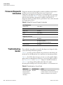
Firmware Diagnostic Information ....................................................... 6-2
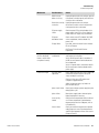
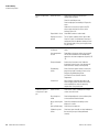
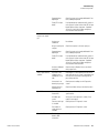
Troubleshooting Guides...................................................................... 6-2
Model 55i Instruction Manual
Thermo Fisher Scientific
Contents
Board-Level Connection Diagrams ..................................................... 6-8
Connector Pin Descriptions .............................................................. 6-10
Performance Problems ...................................................................... 6-22
Normal Chromatograms ................................................................ 6-24
Gas Leak in Column Oven............................................................. 6-25
Contaminated Carrier Gas ............................................................. 6-26
Contaminated Column .................................................................. 6-27
Service Locations............................................................................... 6-29
Chapter 7
Thermo Fisher Scientific
Servicing............................................................................................................. 7-1
Safety Precautions ............................................................................... 7-3
Firmware Updates ............................................................................... 7-4
Accessing the Service Mode................................................................. 7-4
Replacement Parts List ........................................................................ 7-5
Cable List............................................................................................ 7-6
External Device Connection Components .......................................... 7-7
Removing the Measurement Case Assembly and Lowering the Partition
Panel ................................................................................................... 7-9
Pump Replacement ........................................................................... 7-10
Fan/Filter Replacement ..................................................................... 7-12
Input Board Replacement ................................................................. 7-13
Input Board Calibration.................................................................... 7-14
DC Power Supply Replacement ........................................................ 7-15
Analog Output Testing ..................................................................... 7-16
Analog Output Calibration ............................................................... 7-19
Analog Input Calibration .................................................................. 7-20
Calibrating the Input Channels to Zero Volts ................................ 7-20
Calibrating the Input Channels to Full-Scale ................................. 7-21
Thermistor Replacement................................................................... 7-22
Ambient Temperature Calibration .................................................... 7-22
Fuel/Calibraion Solenoid Valve Replacement.................................... 7-24
8-Port Valve Rotor Replacement....................................................... 7-24
Disassembly ................................................................................... 7-25
Cleaning the Valve Body................................................................ 7-26
Cleaning the Rotor......................................................................... 7-27
Assembly ........................................................................................ 7-27
Testing and Replacing the Ignitor ..................................................... 7-28
Checking the Detector Bias Voltage .................................................. 7-30
Removing the Detector ..................................................................... 7-31
Detector Rebuilding.......................................................................... 7-33
Internal Sample Filter Replacement................................................... 7-38
Valve Actuator Repair ....................................................................... 7-39
Disassembly ................................................................................... 7-40
O-Ring Replacement...................................................................... 7-42
Reassembly..................................................................................... 7-43
Rebuilding the Subassembly........................................................... 7-44
Model 55i Instruction Manual
xiii
Contents
Valve Alignment ............................................................................ 7-46
Visually Checking Alignment......................................................... 7-46
Alignment ...................................................................................... 7-47
General Electrical Testing ................................................................. 7-47
Adjusting Critical Gas Flows ............................................................. 7-49
Preliminary Set-Up ........................................................................ 7-49
Adjusting For Hydrogen Fuel......................................................... 7-49
Adjusting For Mixed Fuel (H2/He) ................................................ 7-51
Optimizing the Gas Flows.............................................................. 7-52
Fuse Replacement ............................................................................. 7-54
I/O Expansion Board (Optional) Replacement ................................. 7-54
Digital Output Board Replacement................................................... 7-56
Motherboard Replacement................................................................ 7-56
Measurement Interface Board Replacement ...................................... 7-57
Front Panel Board Replacement........................................................ 7-59
LCD Module Replacement ............................................................... 7-60
Service Locations............................................................................... 7-61
Chapter 8
xiv
Model 55i Instruction Manual
System Description...........................................................................................8-1
Hardware ............................................................................................ 8-1
Flame Ionization Detector (FID) ..................................................... 8-3
Sample Filter.................................................................................... 8-3
Internal Pump.................................................................................. 8-3
Rotary Valve .................................................................................... 8-3
Electronic Pressure Controllers......................................................... 8-3
Separation Column .......................................................................... 8-4
Fuel Shutoff Solenoid....................................................................... 8-4
Calibration Solenoid ........................................................................ 8-4
Firmware............................................................................................. 8-4
Instrument Control.......................................................................... 8-4
Monitoring Signals........................................................................... 8-5
Output Communication .................................................................. 8-5
Electronics .......................................................................................... 8-5
Motherboard.................................................................................... 8-6
Measurement Interface Board .......................................................... 8-6
Measurement Interface Board Connectors..................................... 8-6
Input Board ..................................................................................... 8-7
Digital Output Board....................................................................... 8-7
I/O Expansion Board (Optional) ..................................................... 8-7
Front Panel Connector Board .......................................................... 8-8
I/O Components................................................................................. 8-8
Analog Voltage Outputs................................................................... 8-8
Analog Current Outputs (Optional) ................................................ 8-9
Analog Voltage Inputs (Optional) .................................................... 8-9
Digital Relay Outputs ...................................................................... 8-9
Digital Inputs................................................................................... 8-9
Thermo Fisher Scientific
Contents
Serial Ports ..................................................................................... 8-10
RS-232 Connection ....................................................................... 8-10
RS-485 Connection ....................................................................... 8-11
Ethernet Connection...................................................................... 8-11
External Accessory Connector ........................................................ 8-11
Thermo Fisher Scientific
Chapter 9
Optional Equipment .......................................................................................... 9-1
I/O Expansion Board Assembly........................................................... 9-1
25 Pin Terminal Board Assembly........................................................ 9-1
Terminal Block and Cable Kits ........................................................... 9-1
Cables ................................................................................................. 9-2
Mounting Options.............................................................................. 9-3
Appendix A
Warranty ............................................................................................................ A-1
Appendix B
C-Link Protocol Commands............................................................................ B-1
Instrument Identification Number......................................................B-2
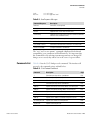
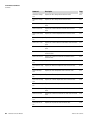
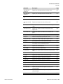
Commands .........................................................................................B-2
Commands List................................................................................B-3
Measurements ...................................................................................B-10
Instrument Control...........................................................................B-12
Alarms...............................................................................................B-13
Diagnostics .......................................................................................B-18
Datalogging.......................................................................................B-22
Calibration........................................................................................B-28
Keys/Display .....................................................................................B-31
Measurement Configuration .............................................................B-32
Hardware Configuration ...................................................................B-35
Communications Configuration .......................................................B-40
I/O Configuration.............................................................................B-48
Record Layout Definition .................................................................B-53
Format Specifier for ASCII Responses............................................B-53
Format Specifier for Binary Responses ...........................................B-54
Format Specifier for Erec Layout....................................................B-54
Text ............................................................................................B-55
Value String ................................................................................B-55
Value Source ...............................................................................B-55
Alarm Information ......................................................................B-55
Translation Table........................................................................B-56
Selection Table............................................................................B-56
Button Designator.......................................................................B-56
Examples.....................................................................................B-57
Appendix C
MODBUS Protocol ............................................................................................C-1
Serial Communication Parameters ..................................................... C-1
Model 55i Instruction Manual
xv
Contents
TCP Communication Parameters ...................................................... C-2
Application Data Unit Definition ...................................................... C-2
Slave Address................................................................................... C-2
MBAP Header ................................................................................ C-2
Function Code ................................................................................ C-3
Data ................................................................................................ C-3
Error Check .................................................................................... C-3
Function Codes.................................................................................. C-3
(0x01/0x02) Read Coils/Read Inputs .............................................. C-3
(0x03/0x04) Read Holding Registers/Read Input Registers ............. C-5
(0x05) Force (Write) Single Coil..................................................... C-7
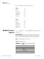
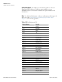
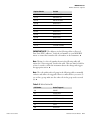
MODBUS Parameters Supported ...................................................... C-8
xvi
Appendix D
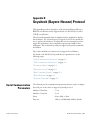
Geysitech (Bayern-Hessen) Protocol...........................................................D-1
Serial Communication Parameters ..................................................... D-1
TCP Communication Parameters ...................................................... D-2
Instrument Address ............................................................................ D-2
Abbreviations Used ............................................................................ D-2
Basic Command Structure ................................................................. D-2
Block Checksum Characters <BCC>.................................................. D-3
Geysitech Commands ........................................................................ D-3
Instrument Control Command (ST)............................................... D-3
Data Sampling/Data Query Command (DA).................................. D-4
Measurements reported in response to DA command ..................... D-6
Operating and Error Status ............................................................. D-6
Appendix E
AK Protocol Commands................................................................................... E-1
TCP Communication Parameters .......................................................E-1
Conventions........................................................................................E-2
Abbreviations Used .............................................................................E-2
Basic Command Structure ..................................................................E-2
Commands List...................................................................................E-3
Measurements .....................................................................................E-3
Alarms.................................................................................................E-5
Calibration..........................................................................................E-6
Measurement Configuration ...............................................................E-7
Hardware Configuration .....................................................................E-8
Communications Configuration .........................................................E-9
Model 55i Instruction Manual
Thermo Fisher Scientific
Figures
Figure 1–1. Rotary Valve Configuration ............................................................. 1-3
Figure 1–2. 8-Port Rotary Valve, Backflush and Inject Positions....................... 1-4
Figure 1–3. Typical Model 55i Span Gas Chromatogram.................................. 1-6
Figure 1–4. Model 55i Flow Schematic ............................................................. 1-7
Figure 2–1. Remove the Packing Material ......................................................... 2-3
Figure 2–2. Model 55i Rear Panel...................................................................... 2-5
Figure 2–3. Atmospheric Dump Bypass Plumbing ............................................. 2-9
Figure 2–4. Suggested Sample and Span Connections with External Pump .. 2-10
Figure 2–5. Suggested Sample and Span Connections with Internal Pump... 2-11
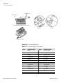
Figure 2–6. I/O Terminal Board Views ............................................................. 2-14
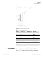
Figure 2–7. Pin-Out of Rear Panel Connector................................................... 2-15
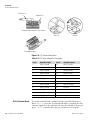
Figure 2–8. D/O Terminal Board Views............................................................ 2-16
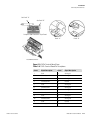
Figure 2–9. 25-Pin Terminal Board Views........................................................ 2-17
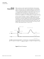
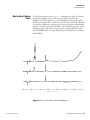
Figure 2–10. Test Chromatograms ................................................................... 2-21
Figure 3–1. Front Panel Display.......................................................................... 3-2
Figure 3–2. Front Panel Pushbuttons.................................................................. 3-2
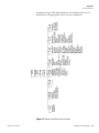
Figure 3–3. Flowchart of Menu-Driven Firmware .............................................. 3-5
Figure 3–4. Pin-Out of Rear Panel Connector................................................... 3-11
Figure 5–1. Inspecting and Cleaning the Fan Filters.......................................... 5-3
Figure 5–2. Cleaning the Internal Filter Element ............................................... 5-5
Figure 5–3. Rebuilding the Pump (New Technology)......................................... 5-7
Figure 5–4. Rebuilding the Pump........................................................................ 5-9
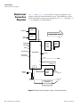
Figure 6–1. Board-Level Connection Diagram - Common Electronics............... 6-8
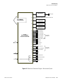
Figure 6–2. Board-Level Connection Diagram - Measurement System ............ 6-9
Figure 6–3. Normal Chromatograms ................................................................ 6-24
Figure 6–4. Gas Leak in Column Oven Chromatograms................................... 6-25
Figure 6–5. Contaminated Carrier Gas Chromatograms.................................. 6-26
Figure 6–6. Contaminated Column Chromatograms........................................ 6-27
Figure 7–1. Properly Grounded Antistatic Wrist Strap ...................................... 7-4
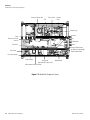
Figure 7–2. Model 55i Component Layout......................................................... 7-8
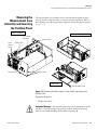
Figure 7–3. Removing the Measurement Case Assembly and Lowering the
Partition Panel ...................................................................................................... 7-9
Figure 7–4. Replacing the Pump....................................................................... 7-11
Figure 7–5. Replacing the Fan .......................................................................... 7-13
Figure 7–6. Replacing the Input Board............................................................. 7-14
Figure 7–7. Replacing the DC Power Supply.................................................... 7-16
Thermo Fisher Scientific
Model 55i Instruction Manual
xvii
Figures
Figure 7–8. Rear Panel Analog Input and Output Pins .....................................7-18
Figure 7–9. Replacing the Thermistor...............................................................7-22
Figure 7–10. 8-Valve Rotor Disassembly..........................................................7-25
Figure 7–11. Valve with Pre-Load Removed.....................................................7-26
Figure 7–12. Holding the Rotor (Viewed from Pre-Load End) ..........................7-27
Figure 7–13. Location of the ID Letter on the Rotor.........................................7-28
Figure 7–14. Removing the Detector ................................................................7-33
Figure 7–15. Rebuilding the Detector...............................................................7-37
Figure 7–16. Removal of a Valve on a Standoff...............................................7-40
Figure 7–17. End Cap Removal .........................................................................7-41
Figure 7–18. Removal of Subassembly from Male End Cap ............................7-41
Figure 7–19. Sliding the O-Ring Plate Off of Shaft ..........................................7-42
Figure 7–20. O-Ring Locations..........................................................................7-42
Figure 7–21. Subassembly Ready to Go On .....................................................7-43
Figure 7–22. O-Ring Plate Orientation..............................................................7-44
Figure 7–23. Two-Position Actuator (Exploded View)......................................7-45
Figure 7–24. Visual Check of Alignment (Rotor Pin Shown in Both Positions.7-46
Figure 7–25. Replacing the I/O Expansion Board (Optional) ............................7-55
Figure 7–26. Rear Panel Board Connectors ......................................................7-55
Figure 7–27. Replacing the Measurement Interface Board .............................7-58
Figure 7–28. Replacing the Front Panel Board and the LCD Module...............7-60
Figure 8–1. Hardware Components ....................................................................8-2
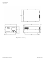
Figure 9–1. Bench Mounting...............................................................................9-4
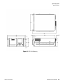
Figure 9–2. EIA Rack Mounting ..........................................................................9-5
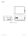
Figure 9–3. Retrofit Rack Mounting....................................................................9-6
Figure 9–4. Rack Mount Option Assembly .........................................................9-7
Figure B–1. Flags Field......................................................................................B-20
xviii
Model 55i Instruction Manual
Thermo Fisher Scientific
Tables
Table 1–1. Inject and Backflush Connections .................................................... 1-3
Table 1–2. Model 55i Specifications ................................................................. 1-7
Table 2–1. I/O Terminal Board Pin Descriptions .............................................. 2-14
Table 2–2. Default Analog Outputs.................................................................. 2-15
Table 2–3. D/O Terminal Board Pin Descriptions............................................. 2-16
Table 2–4. 25-Pin Terminal Board Pin Descriptions......................................... 2-17
Table 3–1. Front Panel Pushbuttons................................................................... 3-3
Table 3–2. Loop Size Range Values ................................................................... 3-9
Table 3–3. Default Analog Outputs.................................................................. 3-11
Table 3–4. Analog Output Zero to Full-Scale ................................................... 3-45
Table 3–5. Signal Type Group Choices............................................................. 3-46
Table 6–1. Model 55i Firmware Diagnostic Information................................... 6-2
Table 6–2. Troubleshooting - General Guide ..................................................... 6-2
Table 6–3. Troubleshooting - Alarm Messages ................................................. 6-6
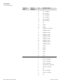
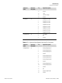
Table 6–4. Motherboard Connector Pin Descriptions...................................... 6-10
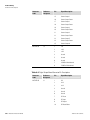
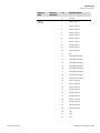
Table 6–5. Measurement Interface Board Connector Pin Descriptions .......... 6-15
Table 6–6. Front Panel Board Connector Pin Descriptions .............................. 6-17
Table 6–7. I/O Expansion Board (Optional) Connector Pin Descriptions ......... 6-19
Table 6–8. Digital Output Board Connector Pin Descriptions.......................... 6-20
Table 6–9. Input Board Connector Pin Descriptions ........................................ 6-22
Table 6–10. Troubleshooting - Performance Problems.................................... 6-28
Table 7–1. Model 55i Replacement Parts.......................................................... 7-5
Table 7–2. Model 55i Cables.............................................................................. 7-6
Table 7–3. External Device Connection Components ........................................ 7-7
Table 7–4. Analog Output Channels and Rear Panel Pin Connections............ 7-18
Table 7–5. Analog Input Channels and Rear Panel Pin Connections............... 7-19
Table 7–6. Part Number and Drawing Reference for Detector Assembly....... 7-38
Table 7–7. Acceptable Heater Resistance Readings....................................... 7-48
Table 8–1. RS-232 DB9 Connector Pin Configuration...................................... 8-11
Table 8–2. RS-485 DB9 Connector Pin Configuration...................................... 8-11
Table 9–1. Cable Options.................................................................................... 9-2
Table 9–2. Color Codes for 25-Pin and 37-Pin Cables ....................................... 9-3
Table 9–3. Mounting Options ............................................................................. 9-3
Table B–1. Error Response Messages ............................................................... B-3
Table B–2. C-Link Protocol Commands .............................................................. B-3
Table B–3. Condition Column Values............................................................... B-12
Thermo Fisher Scientific
Model 55i Instruction Manual
xix
Tables
Table B–4. Alarm Trigger Values......................................................................B-18
Table B–5. Record Output Formats...................................................................B-25
Table B–6. Stream Time Values .......................................................................B-28
Table B–7. Fuel and Status Values...................................................................B-36
Table B–8. Contrast Levels ...............................................................................B-37
Table B–9. Reply Termination Formats ............................................................B-44
Table B–10. Allow Mode Command Values ....................................................B-46
Table B–11. Power up Mode Values ................................................................B-47
Table B–12. Layout Ack Values ........................................................................B-47
Table B–13. Analog Current Output Range Values..........................................B-48
Table B–14. Analog Voltage Output Range Values .........................................B-49
Table B–15. Default Analog Output Channel Assignments.............................B-51
Table C–1. Read Coils for 55i .............................................................................C-8
Table C–2. Read Registers for 55i....................................................................C-10
Table C–3. Write Coils for 55i ..........................................................................C-11
Table D–1. Operating Status for Model 55i ...................................................... D-7
Table D–2. Error Status for Model 55i .............................................................. D-7
Table E–1. Command List....................................................................................E-3
Table E–2. Measurement Values........................................................................E-4
Table E–3. Temperature Values..........................................................................E-5
Table E–4. Alarm Status Descriptions................................................................E-6
Table E–5. Measurement Values........................................................................E-6
Table E–6. Range Values ....................................................................................E-6
Table E–7. Range Values ....................................................................................E-7
Table E–8. Measurement Values........................................................................E-8
Table E–9. Oven Temperature Values ................................................................E-8
Table E–10. Oven Temperature Values ..............................................................E-9
Table E–11. Remote Values ..............................................................................E-10
xx
Model 55i Instruction Manual
Thermo Fisher Scientific
Chapter 1
Introduction
The Model 55i Direct Methane, Non-Methane Hydrocarbon Analyzer is a
back-flush gas chromatography (GC) system designed for automated
measurement of methane and non-methane hydrocarbons. Unlike
instruments that measure only methane and total hydrocarbons, the backflush GC method provides a direct measurement of non-methane
concentrations. This allows accurate and precise measurement of low levels
of non-methane hydrocarbons (NMHC), even in the presence of methane
at much higher concentrations.
The Model 55i has the following features:
●
320 x 240 graphics display
●
Menu-driven firmware
●
Temperature controlled detector oven and sampling system
●
Multiple user-defined analog outputs
●
Analog input options
●
Reporting of alarm conditions
●
Flame-out detection and automatic re-ignition
●
User-programmable report generation
●
User-selectable digital input/output capabilities
●
Standard communications features include RS-232/485 and Ethernet
●
C-Link, MODBUS, Geysitech (Bayern-Hessen), AK, streaming data,
and NTP (Network Time Protocol) protocols. Simultaneous
connections from different locations over Ethernet.
For details of the analyzer’s principle of operation and product
specifications, see the following topics:
Thermo Fisher Scientific
●
“Principle of Operation” on page 1-2
●
“Specifications” on page 1-7
Model 55i Instruction Manual
1-1
Introduction
Principle of Operation
Thermo Fisher Scientific is pleased to supply this direct methane, nonmethane hydrocarbon analyzer. We are committed to the manufacture of
instruments exhibiting high standards of quality, performance, and
workmanship. Service personnel are available for assistance with any
questions or problems that may arise in the use of this analyzer. For more
information on servicing, see Chapter 7, “Servicing”.
Principle of
Operation
The Model 55i’s measurement of methane and non-methane hydrocarbons
is based on the well developed science of gas chromatography and utilizes a
proprietary column system developed specifically for this application. Gas
chromatography is a proven analytical tool that was initially developed in
the 1950’s and is now the most widely applied separation technique in
analytical laboratories. A detailed discussion of chromatographic theory
goes beyond the scope of this manual, and is not necessary for operation of
the analyzer. However, a basic understanding of chromatographic
principals may be helpful for instrument setup and troubleshooting. For
initial installation and operation, the user should become familiar with the
sampling system, the gas flow patterns, the analog signal outputs, and the
hydrocarbon detection and measurement methods described in this
chapter. For those who are interested in a more complete description of the
chromatographic process, a detailed explanation can be found in most
textbooks on analytical instrumentation.
The Model 55i is an automated batch analyzer which repeatedly collects
and analyzes small amounts of the sample stream drawn in by the pump.
Central to the instrument's operation is an eight port, two position, rotary
valve which is used to introduce the gas sample into the analyzer and to
control the flow of gases through the chromatographic column.
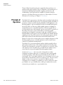
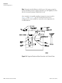
As shown in Figure 1–1, the rotary valve is designed in a circular
configuration with the eight ports, or connection points, spaced equally
around the periphery of the valve body. Internally, the valve includes a
cone shaped "rotor" at the hub, which has a set of 4 channels or grooves cut
in the surface. Each channel connects two adjacent ports. The rotor can be
shifted to either of two positions to provide two different gas flow
configurations. For example, port number two can be connected to either
port number one or port number three, while port number three can be
connected to port number two or port number four.
1-2
Model 55i Instruction Manual
Thermo Fisher Scientific
Introduction
Principle of Operation
Figure 1–1. Rotary Valve Configuration
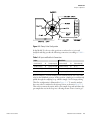
In the Model 55i, the two valve positions are referred to as inject and
backflush and they provide the following connection, according to Table 1–
1:
Table 1–1. Inject and Backflush Connections
Inject
Backflush
Carrier Inlet (5)
Æ
Sample Loop (4)
Carrier Inlet (5)
Æ
Column-back (6)
Sample Loop (1)
Æ
Column-front (8)
Column-front (8)
Æ
FID (7)
Column-back (6)
Æ
FID (7)
Pump Vacuum (2)
Æ
Sample Loop (1)
Pump Vacuum (2)
Æ
Sample Inlet (3)
Sample Loop (4)
Æ
Sample Inlet (3)
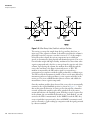
Between analyses, or while running in the stand-by mode, the rotary valve
is left in the backflush position. In this position, sample gas is continuously
pulled through the sampling loop, which is simply a coil of empty tubing.
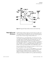
This flow configuration is illustrated in Figure 1–2. To start the analysis,
the rotary valve is switched to the inject position, as shown in Figure 1–2.
This action connects the carrier inlet to the sample loop and introduces the
gas sample that was in the loop into a flowing stream of inert “carrier gas”.
Thermo Fisher Scientific
Model 55i Instruction Manual
1-3
Introduction
Principle of Operation
Figure 1–2. 8-Port Rotary Valve, Backflush and Inject Positions
The carrier gas sweeps the sample from the loop and into the front, or
inject end, of the separation column. It should be noted that the column is
physically located in a separate oven that is run at 65 °C. As the sample is
carried down the column, the various components move at different
speeds, as determined by their physical and chemical properties. Due to its
low molecular weight and high volatility, methane moves faster than other
organic compounds and is the first to emerge from the opposite end of the
column. Upon leaving the column, the methane flows back through the
rotary valve and then to the flame ionization detector, or FID. The
methane is measured by the FID and its signal is converted into a
concentration by comparison with the signal produced by a calibration gas.
The FID used in the instrument is similar to those seen in many laboratory
instruments and uses a hydrogen flame to ionize organic molecules in the
carrier gas. This is an established method that is sensitive and reliable for
measurement of most organic compounds.
Once the methane peak has been detected, the rotary valve is automatically
returned to the original backflush position, as shown in Figure 1–1. Note
that at this point the direction of carrier gas flow through the column has
reversed, and that the sample loop has been switched out of the carrier
stream and back into the sampling system. With the reversal of carrier flow
in the column, the non-methane hydrocarbons are "back-flushed" out and
carried to the FID for measurement. As the NMHCs reach the FID, they
create a signal that is proportional to the total NMHC concentration and
can be converted to a ppm reading by comparison with the signal generated
by a known standard.
1-4
Model 55i Instruction Manual
Thermo Fisher Scientific
Introduction
Principle of Operation
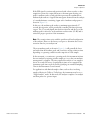
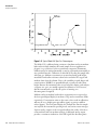
If the FID signal is continuously monitored with a chart recorder or data
acquisition system, the output will create a chromatogram showing one
peak for methane and a second peak that represents the combined nonmethane hydrocarbons. A typical chromatogram obtained from the analysis
of a standard mixture containing 2 ppm each of methane and propane is
shown in Figure 1–3.
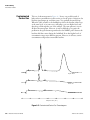
In this case, the methane peak reaches a maximum approximately 17
seconds after injection, and is preceded by a smaller peak that represents
oxygen. The 17-second elapsed time between injection and the top of the
methane peak is referred to as the methane retention time (C1-Rt) and is
critical for proper operation of the instrument.
Note The retention time varies with the specific model and configuration
of the analyzer. Please see the factory test report to determine the correct
retention time for your analyzer. ▲
The non-methane peak, as shown in Figure 1–3, will generally be lower
and wider than the methane peak, and it can have varying retention times
depending on operating conditions and composition of the sample.
In the automatic, or continuous, operating mode, the instrument initiates
the next analysis by injecting another sample as soon as the non-methane
measurement is complete. The time required for analysis of one sample is
about 70 seconds. However, if rapid analysis times are not required, the
instrument cycle time can be slowed by specifying an extended Sampling
Time in the Instrument Controls menu.
For applications with limited sample volume, such as those involving
sample collection in Tedlar or Teflon bags, the instrument may be set to
“Single Analysis” mode. In this mode, the analyzer completes one analysis
and then pauses for operator input.
Thermo Fisher Scientific
Model 55i Instruction Manual
1-5
Introduction
Principle of Operation
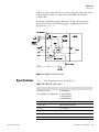
Figure 1–3. Typical Model 55i Span Gas Chromatogram
The Model 55i is calibrated using a mixture of methane and non-methane
hydrocarbons which simulates the actual sample. In most applications,
propane is a good choice for the non-methane component. Instrument
calibration may be initiated manually or may be performed automatically at
user specified intervals. Calibration is achieved by flooding the sample inlet
with span gas. Methane concentrations are measured using peak height,
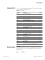
measured from baseline references taken before and after the oxygen and
methane elute from the column. Due to the variability in peak shapes and
retention times, NMHCs are quantified based on peak area rather than
height. Because the instrument takes several references during each analysis,
a separate zero gas is not usually required for calibration. Note however,
that the instrument does provide the option of running zero
chromatograms if required.
Methane and non-methane hydrocarbon concentrations are reported on
the front panel digital display as methane (CH4) and non-methane (NM),
respectively. Concentration units are the same as those used in calibration,
and may be set to display parts per million (ppm) or parts per million
carbon (ppmc). The front panel display also includes the time the sample
was injected, the instrument operating mode, and various status messages.
Separate analog outputs on the rear panel indicate the results of the most
recent methane and non-methane analysis. A dedicated analog output
provides a continuous indication of the FID signal (the chromatogram).
1-6
Model 55i Instruction Manual
Thermo Fisher Scientific
Introduction
Specifications
Other rear panel connections allow for remote operation of the unit, either
by dedicated control lines or with a bi-directional RS-232/Ethernet
computer link.
Performance specifications and a description of important instrument
parameters are listed on the following pages. A plumbing schematic is
presented in Figure 1–4.
Figure 1–4. Model 55i Flow Schematic
Specifications
Table 1–2 lists the specifications for the Model 55i.
Table 1–2. Model 55i Specifications
Thermo Fisher Scientific
Measurement ranges
(CH4 and NMHC set independently)
0–5/50/500 ppm
0–10/100/1000 ppm
0–20/200/2000 ppm
0–50/500/5000 ppm
Limit of detection
50 ppb
Analysis time
Approximately 70 seconds
Accuracy
±1% of range
Repeatability
±2% of measured value or 50 ppb (whichever is larger)
Drift (without auto calibration)
±2% of span over 24 hours
Ambient operating temperature
15–35 °C
Model 55i Instruction Manual
1-7
Introduction
Specifications
Sample temperature
Ambient to 80 °C (standard), higher temperatures
optional
Sample flow rate
0.5 liter/minute minimum
Power requirements
100 VAC @ 50/60 Hz
115 VAC @ 50/60 Hz
220–240 VAC @ 50/60 Hz
420 Watts
Support gases
HC free air (275–350 cc/min)
N2 carrier (35–70 cc/min)
H2 fuel (25–50 cc/min) or mixed fuel (100–150 cc/min)
Span mix (2-liter/calibration)
Physical dimensions
16.75” (W) X 8.62” (H) X 23” (D)
Weight
Approximately 50 lbs.
Analog outputs
6 voltage outputs; 0–100 mV, 1, 5, 10 V (user
selectable), 5% of full-scale over/under range (user
selectable), 12 bit resolution, measurement output user
selectable per channel
Digital outputs
1 power fail relay Form C, 10 relays Form A, user
selectable alarm output, relay logic, 100 mA @ 200
VDC
Digital inputs
16 digital inputs, user select programmable, TTL level,
pulled high
Serial ports
1 RS-232 or RS-485 with two connectors, baud rate
1200–115200, data bits, parity, and stop bits,
protocols: C-Link, MODBUS, Geysitech (BayernHessen), AK, and streaming data (all user selectable)
Ethernet connection
RJ45 connector for 10 Mbs Ethernet connection, static
or dynamic TCP/IP addressing, up to 3 simultaneous
connections per protocol
Note: All NMHC specifications are based on propane.
1-8
Model 55i Instruction Manual
Thermo Fisher Scientific
Chapter 2
Installation
Installation of the Model 55i includes unpacking and inspection,
connecting sample, zero and span lines, attaching the analog and/or digital
outputs to a recording device, and connecting any control or status lines
that will be used. The startup section includes instructions for initial
powerup of of the Model 55i and for adjustment of basic operating
parameters, such as gas pressures. The installation should always be
followed by instrument calibration as described in the “Calibration”
chapter of this manual.
Equipment Damage Do not apply power to the Model 55i until all other
installation procedures have been completed. An incorrect start-up
sequence could damage the instrument. ▲
This chapter provides the following recommendations and procedures for
installing the instrument:
Lifting
Thermo Fisher Scientific
●
“Lifting” on page 2-1
●
“Unpacking and Inspection” on page 2-2
●
“Selecting Hardware and Support Gases” on page 2-3
●
“Connecting Support Gases” on page 2-8
●
“Connecting External Devices” on page 2-13
●
“Startup” on page 2-18
●
“Column Conditioning and Initial Burn-In” on page 2-19
●
“Running Test Chromatograms” on page 2-19
When lifting the instrument, use a procedure appropriate to lifting a heavy
object, such as, bending at the knees while keeping your back straight and
upright. Grasp the instrument at the bottom in the front and at the rear of
the unit. Although one person can lift the unit, it is desirable to have two
persons lifting, one by grasping the bottom in the front and the other by
grasping the bottom in the rear.
Model 55i Instruction Manual
2-1
Installation
Unpacking and Inspection
Equipment Damage Do not attempt to lift the instrument by the cover or
other external fittings. ▲
Unpacking and
Inspection
The Model 55i is shipped complete in one container. If there is obvious
damage to the shipping container when the instrument is received, notify
the carrier immediately and hold for inspection. The carrier is responsible
for any damage incurred during shipment.
Note Save all packing material. If it is ever necessary to ship the instrument
for service, the original packing material should be re-used. It is especially
important to cap all fittings and to wrap the instrument in plastic before
shipment to avoid contamination of the gas lines with packing foam. ▲
Use the following procedure to unpack and inspect the instrument.
1. Remove the instrument from its shipping container and set it on a table
or bench that allows easy access to both the front and rear.
2. Remove the instrument from the plastic bag and remove the caps or
plugs that cover the gas fittings on the rear panel.
3. Remove the cover to expose the internal components.
4. Remove the packing material in the analyzer (Figure 2–1).
2-2
Model 55i Instruction Manual
Thermo Fisher Scientific
Installation
Selecting Hardware and Support Gases
Remove Packing
(2 pieces)
Units without Optional I/O Board
Remove Packing
(2 pieces)
Units with Optional I/O Board
Figure 2–1. Remove the Packing Material
5. Check for possible damage during shipment.
6. Check that all connectors and circuit boards are firmly attached.
7. Re-install the cover.
8. Remove any protective plastic material from the case exterior.
Selecting Hardware
and Support Gases
The Model 55i requires a number of support gases and some external
plumbing for operation. It is important that support gases, regulators, gas
lines, gas scrubbers, and fittings are carefully selected to provide the cleanest
possible support gases to the instrument. Use of inappropriate gas supplies
or hardware will have an adverse affect on performance and can
contaminate the instrument with oils or other organic compounds.
Appropriate hardware and gases can be obtained from chromatography
suppliers and from specialty gas vendors.
The most important consideration in selecting support gases and hardware
is the purity of the carrier gas. Low quality carrier gas produces an erratic
baseline, can elevate non-methane readings, and contaminate the
chromatographic column. Fuel or air contaminated with hydrocarbons can
also affect performance by increasing the FID background signal, which
can interfere with detection of low-level hydrocarbons.
Thermo Fisher Scientific
Model 55i Instruction Manual
2-3
Installation
Selecting Hardware and Support Gases
Gas Pressure
Regulators
All gas cylinders should be fit with high quality one or two stage regulators
with stainless steel diaphragms. These regulators are available from
scientific and specialty gas suppliers and are usually sold as high purity
regulators.
Carrier gas, fuel, combustion air, and actuator air must be delivered to the
Model 55i at controlled pressures, which range between 40 and 80 psi as
stated below:
●
Combustion Air:
●
Fuel:
40 - 80 psi
●
(hydrogen)
40 - 60 psi
●
(hydrogen/helium)
70 - 80 psi
●
Carrier:
40 - 60 psi
●
Actuator Air:
40 - 45 psi
Note Do not use general purpose, industrial, or welding regulators that
usually have a rubber or polymeric diaphragm. Polymeric diaphragms tend
to give off organic compounds that will interfere with the instrument
operation. ▲
Plumbing Lines and
Fittings
All support gases are connected to the rear panel of the instrument using
1/4-inch OD tubing and compression fittings (see Figure 2–1). To avoid
potential leaks that could result from mixing of different fitting types, use
the hardware supplied with the instrument.
If additional fittings are required, contact the service department for
recommendations on selecting the correct materials. Choice of gas lines
should be given careful consideration. While lines made of plastic materials
such as Teflon, are easy to handle, they can give off organic vapors and are
sometimes permeable to permanent gases. For best performance, the use of
pre-cleaned, GC grade copper or steel is recommended. In most cases, precleaned copper tubing purchased from a GC supply house is
recommended. If other materials are used, the lines should be kept as short
as possible.
2-4
Model 55i Instruction Manual
Thermo Fisher Scientific
Installation
Selecting Hardware and Support Gases
Figure 2–2. Model 55i Rear Panel
Gas Scrubbers
Gas scrubbers that remove traces of oxygen, hydrocarbons, and water vapor
from the support air and fuel are available from chromatography suppliers.
If the highest-grade support gases are used, scrubbers are generally not
needed. However, if mid or low grade air and fuel is used, scrubbers may
improve performance of the analyzer. Scrubbers are especially helpful if the
instrument is being operated with breathing quality air or with house air
from a compressor.
Note If hydrocarbon scrubbers containing charcoal or molecular sieve are
installed, these devices do not remove methane, which is the most common
hydrocarbon contaminant. In addition, scrubbers must be replaced or
refilled on a regular basis to maintain performance. Failure to provide
routine maintenance will result in loss of scrubber performance, and in
some cases, can cause increased levels of contamination in the support
gases. Because the carrier gas must be ultra-high purity grade, the addition
of scrubbers to the carrier line will not usually improve performance, and in
some cases can even introduce problems. ▲
Combustion Air
Thermo Fisher Scientific
A continuous supply of air is required to support the FID flame. To
provide enough air for operation of the FID, the air pressure coming into
the instrument must be set between 40 and 80 psi, and the system must be
able to supply at least 400 milliliters per minute of flow.
Model 55i Instruction Manual
2-5
Installation
Selecting Hardware and Support Gases
Compressed air is available in several grades, or quality levels, with higher
grades being more expensive. The grade of the support air will have some
effect on performance, especially when measuring low concentrations of
hydrocarbons. For applications involving hydrocarbon measurements
below 1 or 2 ppm, ultra zero or ultra high purity air containing less than 0.1
ppm of total hydrocarbons is the best choice.
Ultra zero grade air is available in cylinders from scientific gas suppliers, or
can be obtained from a zero air generator, such as the Thermo Scientific’s
Model 1160.
For less critical applications, involving measurement of hydrocarbons at
concentrations of about 2 ppm or higher, zero air with up to 1 ppm
hydrocarbons can be run through charcoal or molecular sieve scrubbers,
and used as FID support air.
Compressed air from an industrial house air system can also be used, but
will require an oil trap, a particulate filter, a water scrubber, and a
hydrocarbon scrubber. These filters and traps will ensure that no harmful
contaminants reach the instrument.
Actuator Air
FID Fuel
To operate the rotary valve actuator, the actuator air pressure coming into
the instrument must be set between 40 and 45 psi, and the system must be
able to supply at least 2 liters per minute of flow. Air pressures in excess of
45 psi can reduce the service life of the valve actuator and pressures lower
than 40 psi may cause erratic performance. The same air source that
supplies the combustion air can be used for the actuator air, as long as the
pressure is between 40 and 45 psi. Alternatively, less expensive air grades
can be used to drive the valve.
The Model 55i FID operates most efficiently with high purity hydrogen
fuel. However, pre-mixed helium/hydrogen fuel can also be used. The air
purity considerations discussed earlier can also apply to the fuel.
For critical applications, ultra high purity hydrogen is available with purity
levels of 99.999 percent or better. For less demanding applications, prepurified or zero grade fuels with total hydrocarbon content of less than 0.5
ppm will be adequate. A good quality hydrogen generator is also an
excellent source of FID fuel.
If the instrument operates with a mixed helium/hydrogen fuel, the ratio
should be 40% hydrogen and 60% helium. This is a standard mixture
available from most scientific gas suppliers and is sold as FID fuel with a
total hydrocarbon content of less than 0.5 ppm.
2-6
Model 55i Instruction Manual
Thermo Fisher Scientific
Installation
Selecting Hardware and Support Gases
Note Operation with mixed fuel requires approximately 2.5 times higher
fuel flow than hydrogen. A special mixed fuel flow restrictor that provides
adequate flow is available from Thermo Fisher Scientific. For further
information regarding operation with mixed fuels, contact the service
department. ▲
Carrier Gas
In addition to air and fuel for the FID, the instrument also requires a
supply of carrier gas to sweep the sample through the column.
Of the three gases used by the instrument, the purity of the carrier gas is
the most important consideration. Low-grade carrier gases will produce an
unstable baseline, elevated NMHC readings, and can eventually
contaminate the column. For most applications, ultra-high-purity (UHP)
nitrogen (99.999%) is the best carrier gas. For laboratory installations, use
of boil-off from a liquid nitrogen cylinder is also a good choice.
Calibration Gas
The Model 55i requires a calibration, or span gas, mixture containing
known concentrations of methane and a non-methane hydrocarbon. For
most applications, the non-methane hydrocarbon should be propane, and
the gas mixture should be prepared in hydrocarbon free air. Calibration
mixtures of methane and propane in air are readily available from scientific
gas suppliers, and will remain stable for at least several months. The
concentrations of methane and propane in the calibration gas should be
about 80% of the concentrations expected in the sample. However, the
methane concentration should not be less than 2 ppm and the propane
concentration should not be less than 1 ppm.
If calibration at less than 2 ppm methane is required for very small
concentrations, an alternate calibration gas must be used. The instrument is
set to measure and interpret the highest peak as the methane concentration.
Since ambient air is 2 ppm methane, a calibration gas standard with a
balance of nitrogen is required.
Various grades or qualities of span gas are available. However, it should be
noted that the accuracy of the Model 55i measurement can be no better
than the accuracy of the calibration standard. For most applications a
calibration gas that has been analyzed with an accuracy of ±2% will be
sufficient.
If the sample being monitored is known to contain specific hydrocarbons
other than methane and propane, a custom span gas containing those same
components can often be obtained. In most cases, a custom mixture that is
similar to the gas stream being monitored will provide the most accurate
calibration. However, custom mixtures are more expensive and may be less
stable. Information concerning custom calibration gases can be obtained
from scientific gas suppliers.
Thermo Fisher Scientific
Model 55i Instruction Manual
2-7
Installation
Connecting Support Gases
As a GC based system, the Model 55i automatically resets the baseline
during each analysis, thus a separate zero gas is not essential for calibration.
If required by regulations or the specific application, a “zero
chromatogram” can be run to establish an instrument baseline that will
then be subtracted from subsequent analytical cycles. If a zero
chromatogram will be used, the zero air mut be ultra-zero grade with total
hydrocarbons of less than 0.1 ppm.
Connecting
Support Gases
Air, fuel, and carrier gas are connected to the rear panel bulkheads using
1/4 -inch OD line and the compression fittings supplied with the
instrument (see Figure 2–1).
Note There are two air inlets on the rear panel. The AIR inlet supplies the
FID and the ACTUATOR inlet supplies the rotary valve actuator. In cases
where the high purity air supply is limited, the rotary valve actuator may be
driven by a lower grade air supply or dedicated compressor. ▲
Sample Inlet
Connect the sample line to the bulkhead fitting labeled SAMPLE INLET
using the 1/4-inch compression fitting that is provided. If the sample is
expected to contain particulate material, a filter should be included in the
sample line to protect the rotary valve.
The sample should be presented to the instrument at a stable pressure near
normal atmospheric levels. The instrument's internal pump can work
against a vacuum of about 10-inches of water and will draw sample through
at least 100-feet of 1/4-inch OD sample line. If sample is being drawn from
a source that operates under strong negative pressure, an external pump
should be considered. For further information, contact the service
department.
If the inlet is connected to a source that operates above atmospheric
pressure, or if an external pump will be used, the sampling line must be
vented to avoid pressurizing the inlet. In some cases, it may be preferable to
shut off or remove the internal pump and add a bypass. Figure 2–3
illustrates the atmospheric dump bypass plumbing required when an
external pump is used.
Fluctuations of sample inlet pressures may cause problems with
repeatability and accuracy of hydrocarbon measurements. If the inlet
pressure is expected to fluctuate, an external pump may be added, or in
some cases a backpressure regulator can be included in the sampling
system. In addition, if the sample is being drawn from a high temperature
source, a heated sample line is required, and the bulkhead connection must
be wrapped with insulation to avoid formation of a cold spot.
2-8
Model 55i Instruction Manual
Thermo Fisher Scientific
Installation
Connecting Support Gases
CAUTION During operation, the sample intake, sample bypass, and FID
exhaust bulkheads are extremely hot. Use caution when working with a hot
instrument. ▲
Instrument Bulkhead
Vent to Exhaust Line at
Atmospheric Pressure
SAMPLE
Input Gas Line
delivering sample at
positive pressure
Figure 2–3. Atmospheric Dump Bypass Plumbing
Span Gas
Connections
Span gas must be introduced to the instrument through the sample inlet.
The internal span control valve allows the instrument micro-processor to
turn the span gas on and off, but it does not connect the span gas to the
sampling system.
If the internal span valve will be used, connect the span gas cylinder to the
port labeled CALIBRATION GAS IN and adjust the cylinder pressure to
10 to 15 psi. Internally, the CALIBRATION GAS IN port is connected to
the CALIBRATION GAS OUT port through a two-way solenoid valve
and a flow restrictor. The CALIBRATION GAS OUT port must be
connected to the sample probe or sample line outside the instrument using
a “tee” fitting and check valve, or some other similar arrangement.
As a general rule, the span gas should be introduced in a manner that
simulates the sample inlet as closely as possible. For example, if a long
sample line is being used, the span gas should be introduced at the end of
the sample line near the probe rather than close to the instrument.
Thermo Fisher Scientific
Model 55i Instruction Manual
2-9
Installation
Connecting Support Gases
Note During the initial calibration, the flow rate of the span gas must be
monitored and the pressure regulator adjusted to provide slightly more flow
than the instrument pump normally draws in. ▲
Some examples of acceptable sampling arrangements are presented in
Figure 2–4 and Figure 2–5. If you are unsure about the correct
configuration for your installation, contact the service department for
recommendations.
Figure 2–4. Suggested Sample and Span Connections with External Pump
2-10
Model 55i Instruction Manual
Thermo Fisher Scientific
Installation
Connecting Support Gases
Figure 2–5. Suggested Sample and Span Connections with Internal Pump
Sample ByPass and
FID Exhaust
The FID exhaust and bypass exhaust are located in the lower-right corner
of the rear panel next to the sample inlet. On some models there may be a
second bypass exhaust located in the lower left corner of the rear panel. In
this case, only one of the two bypass exhausts will be in use.
The FID exhaust gas is composed primarily of air and water vapor with
some products of combustion. If the instrument is located in a room with
reasonable ventilation, the FID exhaust can usually be left open to the
atmosphere without creating a hazard. However, if the instrument is
located in a small confined space, such as a closed cabinet, it is preferable to
run an exhaust line outside or to a ventilation system. If an exhaust line is
used, it should be as short as possible and the diameter should be as large as
possible to prevent pressurizing the FID. Since the FID flame produces
steam, any exhaust line that is used must be configured to slope down away
from the instrument to drain off condensation.
Excess sample flows out one of the ports labeled BYPASS at a rate of up to
one liter per minute. If the sample stream contains potentially hazardous
materials, the bypass should be connected to a ventilation system.
Otherwise, the bypass may be left open. If an exhaust line is connected to
the bypass, the connection should be as short as possible and should open
Thermo Fisher Scientific
Model 55i Instruction Manual
2-11
Installation
Connecting Support Gases
at near-atmospheric pressure. Do not connect the sample by-pass and the
FID exhaust port to the same line, or to a strong vacuum, such as another
pump.
When designing your installation, be aware that changes in the bypass
pressure can affect the pump sampling rate and may also affect the accuracy
of the analysis. Because of the importance of sample pressure, and because
air is mixed with the sample by the pump solenoid, the bypass should not
be used to supply sample to another instrument without consulting the
service department.
Power Connection
The only electrical connection needed for start-up of the Model 55i is the
power cord, which plugs into a receptacle on the rear panel (Figure 2–2).
Before the power cord is connected, be sure that the front panel power
switch is off.
WARNING The Model 55i is supplied with a three-wire grounded power
cord. Under no circumstances should this grounding system be defeated. ▲
For detailed information about connecting to the instrument, refer to:
“Connecting External Devices” on page 2-13
“Instrument Controls Menu” on page 3-18
“I/O Configuration” on page 3-38
“Connector Pin Descriptions” on page 6-10
“Terminal Block and Cable Kits” on page 9-1
For detailed information about troubleshooting a connection, refer to
“Analog Output Testing” on page 7-16.
2-12
Model 55i Instruction Manual
Thermo Fisher Scientific
Installation
Connecting External Devices
Connecting
External Devices
Several components are available for connecting external devices to iSeries
instruments.
These connection options include:
●
Individual terminal board PCB assemblies (standard)
●
Terminal block and cable kits (optional)
●
Individual cables (optional)
For detailed information on the optional connection components, refer to
the “Optional Equipment” chapter. For associated part numbers, refer to
“External Device Connection Components” on page 7-7.
Terminal Board PCB
Assemblies
The terminal board PCB assemblies are circuit boards with a D-Sub
connector on one side and a series of screw terminals on the other side.
This assembly provides a convenient mechanism for connecting wires from
a data system to the analyzer’s I/O connectors.
The following terminal board PCB assemblies are available for iSeries
instruments:
I/O Terminal Board
●
I/O terminal board PCB assembly, 37 pin (standard)
●
D/O terminal board PCB assembly, 37 pin (standard)
●
25-pin terminal board PCB assembly, (included with optional I/O
expansion board)
Figure 2–6 shows the recommended method for attaching the cable
(customer supplied) to the terminal board using the included tie-down and
spacer. Table 2–1 identifies the connector pins and associated signals.
Note Not all of the I/O available in the instrument is brought out on the
supplied terminal board. If more I/O is desired, an alternative means of
connection is required. See optional “Terminal Block and Cable Kits”. ▲
Thermo Fisher Scientific
Model 55i Instruction Manual
2-13
Installation
Connecting External Devices
See Detail “B”
See Detail “A”
Component Side Viewed from Top of Board
Detail “A”
Detail “B”
Assembled Connector
Figure 2–6. I/O Terminal Board Views
Table 2–1. I/O Terminal Board Pin Descriptions
2-14
Model 55i Instruction Manual
Screw
Signal Description
Screw
Signal Description
1
Analog1
13
Power_Fail_NC
2
Analog ground
14
Power_Fail_COM
3
Analog2
15
Power_Fail_NO
4
Analog ground
16
TTL_Input1
5
Analog3
17
TTL_Input2
6
Analog ground
18
TTL_Input3
7
Analog4
19
TTL_Input4
8
Analog ground
20
Digital ground
9
Analog5
21
TTL_Input5
10
Analog ground
22
TTL_Input6
11
Analog6
23
TTL_Input7
12
Analog ground
24
Digital ground
Thermo Fisher Scientific
Installation
Connecting External Devices
The analog outputs are arranged on the rear panel connector as shown in
Figure 2–7. See Table 2–2 for channels and pin connections.
Figure 2–7. Pin-Out of Rear Panel Connector
Table 2–2. Default Analog Outputs
Channel
Connector Pin
I/O Terminal Pin
Description
1
14
1
FID Signal
2
33
3
Methane
3
15
5
NMHC
4
34
7
THC
5
17
9
None
6
36
11
None
Ground
16, 18, 19, 35, 37
2, 4, 6, 8, 10, 12
Signal Ground
Note All channels are user definable. If any customization has been made
to the analog output configuration, the default selections may not apply. ▲
D/O Terminal Board
Thermo Fisher Scientific
Figure 2–8 shows the recommended method for attaching the cable
(customer supplied) to the terminal board using the included tie-down and
spacer. Table 2–3 identifies the connector pins and associated signals.
Model 55i Instruction Manual
2-15
Installation
Connecting External Devices
See Detail “A”
See Detail “B”
Component Side Viewed from Top of Board
Detail “A”
Detail “B”
Assembled Connector
Figure 2–8. D/O Terminal Board Views
Table 2–3. D/O Terminal Board Pin Descriptions
25-Pin Terminal Board
2-16
Model 55i Instruction Manual
Screw
Signal Description
Screw
Signal Description
1
Relay1_ContactA
13
Relay7_ContactA
2
Relay1_ContactB
14
Relay7_ContactB
3
Relay2_ContactA
15
Relay8_ContactA
4
Relay2_ContactB
16
Relay8_ContactB
5
Relay3_ContactA
17
Relay9_ContactA
6
Relay3_ContactB
18
Relay9_ContactB
7
Relay4_ContactA
19
Relay10_ContactA
8
Relay4_ContactB
20
Relay10_ContactB
9
Relay5_ContactA
21
(not used)
10
Relay5_ContactB
22
+24V
11
Relay6_ContactA
23
(not used)
12
Relay6_ContactB
24
+24V
The 25-pin terminal board is included with the optional I/O Expansion
Board. Figure 2–9 shows the recommended method for attaching the cable
(customer supplied) to the terminal board using the included tie-down and
spacer. Table 2–4 identifies the connector pins and associated signals.
Thermo Fisher Scientific
Installation
Connecting External Devices
See Detail “A”
See Detail “B”
Component Side Viewed from Top of Board
Detail “A”
Detail “B”
Assembled Connector
Figure 2–9. 25-Pin Terminal Board Views
Table 2–4. 25-Pin Terminal Board Pin Descriptions
Thermo Fisher Scientific
Screw
Signal Description
Screw
Signal Description
1
IOut1
13
Analog_In1
2
Isolated ground
14
Analog_In2
3
IOut2
15
Analog_In3
4
Isolated ground
16
Ground
5
IOut3
17
Analog_In4
6
Isolated ground
18
Analog_In5
7
IOut4
19
Analog_In6
8
Isolated ground
20
Ground
9
IOut5
21
Analog_In7
10
Isolated ground
22
Analog_In8
11
IOut6
23
Ground
12
Isolated ground
24
Ground
Model 55i Instruction Manual
2-17
Installation
Startup
Startup
Instrument start-up should be performed in the order specified below. It is
especially important not to turn on the power and heat the ovens until after
the carrier gas has been connected and turned on.
Equipment Damage Heating the column oven while the carrier gas is not
flowing may damage the column. ▲
1. Turn on all gas cylinders and adjust cylinder regulators to the following
pressures.
●
Fuel:
●
Hydrogen
60 psi
●
Helium-Hydrogen Mix
80 psi
●
Combustion Air:
80 psi
●
Actuator Air:
45 psi
●
Carrier Gas:
60 psi
●
Span Gas:
15 psi
2. Slightly loosen each fitting at the rear of the instrument for about 30
seconds to bleed off air trapped in the lines and scrubbers, and then retighten the fittings.
3. Turn on the main power switch and note whether any error messages
are reported. After a brief diagnostic test, the instrument will enter the
“Warm-Up” mode. The instrument will require about 90 minutes to
warm up to full operating temperature.
Note The fuel pressure will read zero during warm-up because the fuel
solenoid is automatically closed. The solenoid may be opened using a
screen in the Service menu. ▲
4. When the instrument has stabilized at the correct operating
temperature, the fuel solenoid will automatically open and the
instrument will attempt to light the FID. If ignition fails, the fuel will
be shut off, and the front screen will prompt the user to press
to
try again. During the ignition cycle, check the fuel pressure, and if
necessary, adjust to match the value shown on the factory test sheet.
2-18
Model 55i Instruction Manual
Thermo Fisher Scientific
Installation
Column Conditioning and Initial Burn-In
5. If the pump is currently off, turn it on using the pump settings on/off
screen in the Instrument Controls menu, and then press
to start
automatic analyses using the factory entered parameters and calibration.
6. If the instrument fails to start, or if the FID fails to light, refer to the
“Troubleshooting” chapter and the “Servicing” chapter in this manual.
Column
Conditioning and
Initial Burn-In
Although all Model 55i analyzers are optimized and run for at least two
days at the factory before shipment, most units require a short burn-in
period after installation. The simplest procedure for achieving stable
operation is to follow the startup procedures described above and then run
the built-in column conditioning routine. The column conditioning
routine automatically raises the oven temperatures for a period of 8 hours,
which then helps condition the column and clean out any accumulated
hydrocarbons.
Use the following procedure to initiate a column conditioning cycle.
1. From the Main Menu, choose Service.
Note If Service Mode is not displayed, refer to “Accessing the Service
Mode” on page 7-4. ▲
2. At the Service menu, press
.
then press
3. Press
to scroll down to Condition Column,
to begin column conditioning.
The instrument will now raise the oven temperatures and start a timer.
After eight hours, the instrument will return to normal operating
temperatures.
Running Test
Chromatograms
Following installation and burn-in, it is advisable to obtain a series of test
chromatograms to ensure that the instrument is operating correctly. In
order to obtain chromatograms, it is necessary to connect a chart recorder
or data acquisition system the BNC connector on the rear panel of the
instrument (FID signal).
For initial tests, the chart recorder's input range should be set to about half
of the instrument’s output range. That is, if the Model 55i outputs are set
to the default range of 0-10 volts, the chart recorder should be set for a
fullscale deflection at 5 volts. The chart speed should be high enough so
that the shape of each chromatographic peak is clearly defined. In most
Thermo Fisher Scientific
Model 55i Instruction Manual
2-19
Installation
Running Test Chromatograms
cases, a speed of 5 to 10 inches per minute will provide good results. If a
computer based data acquisition system will be used rather than a chart
recorder, the sampling rate should be set to at least 10 Hz.
Test chromatograms should include a blank, a zero air analysis, and a span
mix. A set of sample chromatograms is shown in Figure 2–10, and
procedures for obtaining each type of chromatogram are presented below.
Ideally, all test chromatograms should look similar, except for the presence
or absence of peaks for methane, NMHCs, and oxygen. Although spikes
occurring at the time of injection and backflush are normal, the baseline
should recover within five seconds and should otherwise appear flat and
relatively noise free. In the case that test chromatograms do not appear
similar to the examples shown here, see the “Troubleshooting” chapter in
this manual.
2-20
Blank
A blank chromatogram consists of an injection and backflush of instrument
carrier gas. This can be achieved by disconnecting the sample line from the
back of the analyzer, turning off the pump and then running a series of five
or more analysis cycles. During the initial two or three cycles, the
instrument will probably report a non-zero value for methane and nonmethane hydrocarbons, and the chromatograms will show peaks for air,
methane and non-methane hydrocarbons. However, after a few cycles, the
instrument readings should drop to zero. At that point, the chromatograms
should appear flat, other than the pressure pulses caused by the valve
switching.
Zero Air
Although zero air is not required for calibration, a test chromatogram made
with hydrocarbon-free zero air may be useful for evaluation of instrument
performance. In order to obtain a zero chromatogram, attach a source of
hydrocarbon free air to the sample inlet and, with the pump on, run a
series of five to seven analysis cycles. Be sure to include a vent, or
atmospheric pressure dump, in the sampling system to prevent pressurizing
the inlet. After two to three analysis cycles, the methane and non-methane
readings should drop to 0.00 ppm and the associated peaks should
disappear from the chromatogram. As illustrated in Figure 2–10, the
chromatogram will show one small peak, representing oxygen that was not
present in the blank chromatogram. Also, it should be noted that many
zero air sources do not completely remove methane and it is not unusual
for the zero air chromatogram to show a small peak at the normal location
of methane.
Model 55i Instruction Manual
Thermo Fisher Scientific
Installation
Running Test Chromatograms
Span
The final test chromatogram should be run with a calibration mixture
containing methane and a non-methane hydrocarbon, in air. For most
applications a mixture containing approximately 2 ppm each of methane
and propane will provide a good test gas. As with the zero test, the gas
mixture for the span test gas should be introduced through the sample
inlet, and a vent should be included to avoid pressurizing the system.
M e th a n e P e a k
N o n -M e th a n e P e a k
A ir P e a k
B a c k f lu s h
I n je c t io n
Span
Z e ro G a s
C a r r ie r G a s / B la n k
-5
5
15
25
35
E la p s e d T im e ( s e c )
45
55
65
Figure 2–10. Test Chromatograms
Thermo Fisher Scientific
Model 55i Instruction Manual
2-21
Chapter 3
Operation
This chapter describes the front panel display screens, front panel
pushbuttons, and menu-driven firmware. For details, see the following
topics:
Display
Thermo Fisher Scientific
●
“Display” on page 3-1
●
“Pushbuttons” on page 3-2
●
“Firmware Overview” on page 3-4
●
“Range Menu” on page 3-8
●
“Calibration Parameters Menu” on page 3-12
●
“Calibration” on page 3-18
●
“Instrument Controls Menu” on page 3-18
●
“Diagnostics Menu” on page 3-52
●
“Alarms Menu” on page 3-62
●
“Service Menu” on page 3-73
●
“Password Menu” on page 3-94
The 320 x 240 graphics liquid-crystal display (LCD) shows the sample
concentrations, instrument parameters, instrument controls, help, and error
messages. Some menus contain more items than can be displayed at one
and
to move the cursor up and
time. For these menus, use
down to each item.
Model 55i Instruction Manual
3-1
Operation
Pushbuttons
Figure 3–1. Front Panel Display
CAUTION If the LCD panel breaks, do not let the liquid crystal contact
your skin or clothes. If the liquid crystal contacts your skin or clothes, wash
it off immediately using soap and water. ▲
Pushbuttons
The Pushbuttons allow the user to traverse the various screens/menus.
Figure 3–2. Front Panel Pushbuttons
3-2
Model 55i Instruction Manual
Thermo Fisher Scientific
Operation
Pushbuttons
Table 3–1 lists the front panel pushbuttons and their functions.
Table 3–1. Front Panel Pushbuttons
Key Name
Function
= Soft Keys
The
(soft keys) are used to provide shortcuts that
allow the user to jump to user-selectable menu screens. For
more information on processing soft keys, see “Soft Keys”
below.
= Run
is used to display the Run screen. The Run
The
screen normally displays the measurement of methane and
non-methane organics.
= Menu
The
is used to display the Main Menu when in the
Run screen, or back up one level in the menu system. For
more information about the Main Menu, see “Main Menu”
later in this chapter.
= Help
The
is context-sensitive, that is, it provides
additional information about the screen that is being
displayed. Press
for a brief explanation about the
current screen or menu. Help messages are displayed using
lower case letters to easily distinguish them from the
operating screens. Press
to return to the Run
screen, or any other key to exit a help screen.
= Up, Down
= Left, Right
= Enter
Soft Keys
,
,
, and
The four arrow pushbuttons (
) move the cursor up, down, left, and right or
change values and states in specific screens.
The
is used to select a menu item, accept/set/save
a change, and/or toggle on/off functions.
The soft keys are multi-functional keys that use part of the display to
identify their function. The function of the soft keys is to provide a
shortcut to the most often used menus and screens. They are located
directly underneath the display, and user-defined labels in the lower part of
the display indicate the function of each key at that time.
To change a soft key, place the menu cursor “>” on the item of the selected
menu or screen you wish to set. Press
followed by the desired soft
key within 1 second of pressing the right-arrow key. The “edit soft key
prompt” will be displayed for configuration of the new label.
Note Not all menu items may be assigned to soft keys. If a particular menu
or screen item cannot be assigned, the key assignment screen will not come
up upon entering right-arrow-soft key combinations. All items under the
Service menu (including the menu itself) cannot be assigned soft keys. ▲
Thermo Fisher Scientific
Model 55i Instruction Manual
3-3
Operation
Firmware Overview
EDIT SOFT KEY PROMPT:
CURRENTLY: RANGE
RANGE
ABCDEFGHIJKLMN BKSP
OPQRSTUVWXYZ
PAGE
0123456789_./- SAVE
RANGE INST
Alphanumeric Entry
Screen
DIAGS ALARM
The alphanumeric entry screen is used to enter strings consisting of letters,
numbers, and other characters. The cursor may be positioned within the
entry line using the
and
keys. If a character is entered over an
and
existing character, that character will be overwritten. Use the
keys to switch between the entry line and the keyboard as well as to
move within the keyboard. To select a character to add to the string, use
the cursor keys to position the cursor over the desired character, and then
press the
key to add that character to the entry line.
On the right side of the keyboard are special functions. BKSP is used to
move the cursor in the entry line one place to the left, deleting the
character that was to the left of the cursor and moving any character at or
to the right of the cursor one place to the left. PAGE is used to change the
keyboard character page. For the English language, this switches between
upper and lower-case alphabetic characters. SAVE stores the string from the
entry line into the parameter. Alternately, if the active cursor is moved to
the entry line,
may be pressed to store the string from the entry line
into the parameter.
Entry Line
ANGE
ABCDEFGHIJKLMN
OPQRSTUVWXYZ
0123456789_./-
Keyboard
RANGE
Firmware
Overview
3-4
Model 55i Instruction Manual
AVG
BKSP
PAGE
SAVE
DIAGS ALARM
ANGE
abcdefghijklmn
opqrstuvwxyz
0123456789_./RANGE
AVG
BKSP
PAGE
SAVE
DIAGS ALARM
The Model 55i utilizes the menu-driven firmware as illustrated by the
flowchart in Figure 3–3. The Power-Up screen, shown at the top of the
flowchart, is displayed each time the instrument is turned on. This screen is
displayed while the instrument is warming up and performing self-checks.
After the warm-up period, the Run screen is automatically displayed. The
Run screen is the normal operating screen. This screen provides the
measurement of methane and non-methane organics along with some
additional information concerning the instrument status. From the Run
screen, the Main Menu can be displayed by pressing
. The Main
Menu contains a list of submenus. Each submenu contains related
Thermo Fisher Scientific
Thermo Fisher Scientific
Conc Units
Methane Range
NMHC Range
Range
Gas Conc
Auto Cal Setup
Auto Verification
Min Verification Cycles
Use Zero Chromatogram
Reset User Cal Defaults
Calibration
Parameters
Calibration
Set Oper Mode
Sampling Time
Reponse Factor
Gas Pressures
Col Oven Enable
Det Oven Enable
Pump Settings
Datalogging Settings
Comm Settings
I/O Config
Screen Contrast
Service Mode
Date/Time
Timezone
Instrument
Controls
Main Menu
Run Screen
Self Test
Screen
Power−up
Screen
Program Versions
Man Operation
Voltages
Temps
Pressure
FID Status
Flame Out Powerup Info
Cal History
Run History
Analog Input Readings
Analog Input Voltages
Digital Inputs
Relay States
Test Analog Outputs
Instrument Config
Contact Info
Diagnostics
Alarms Detected
Internal Temp
Detector Temp
Filter Temp
Column Temp
Flame Out
Carrier Pressure
Fuel Pressure
Air Pressure
CH4 Overrange
NMHC Overrange
Data Integrity
Bias Voltage
Heater Fail
Temp Sensor Fail
Ignitor Check
CH4 Span Check
NMHC Span Check
Window Sanity
CH4 Cal Fail
NM Cal Fail
Methane Conc
Non−Methane Conc
External Alarms
MB Status
Interface Status
I/O Exp Status
Alarms
Set Oven Temps
Man Fuel Valve Bypass
Bypass Flame Detection
Idle Mode
Select Fuel
Auto Range Change
Use Flat Baseline
Condition Column
Set Window Timing
Crucial Settings
Set Pressure and Flow
Input Board Cal
Temp Cal
Leak Test
Analog Out Cal
Analog Input Cal
Display Pixel Test
Restore User Defaults
Service
Set Password
Lock Instrument
Change Password
Remove Password
Unlock Instrument
Password
Operation
Firmware Overview
instrument settings. This chapter describes each submenu and screen in
detail. Refer to the appropriate sections for more information.
Figure 3–3. Flowchart of Menu-Driven Firmware
Model 55i Instruction Manual
3-5
Operation
Firmware Overview
Power-Up Screen
The Power-Up screen is displayed when power is applied to the Model 55i.
This screen is displayed while the internal components are warming up and
diagnostic checks are being performed.
Please wait while booting...
Run Screen
The Run screen displays the current methane and non-methane
concentrations. The status bar displays the time, the password (lock) icon,
service (wrench) icon, alarm (bell) icon, and optional zero/span sample
solenoid valve status, if installed.
Status Bar Icons
The password (lock) icon indicates that
no parameter changes can be made from
the front panel.
The alarm (bell) icon indicates
that an alarm is active.
The service (wrench) icon indicates that the
instrument is in the service mode.
The title bar on the top of the screen indicates the current status of the
instrument and operating mode. During power-up, the title bar displays
“HOT START”, “WARM START”, or “COLD START”. After 15
seconds, the title bar will change to “WARMING UP”.
During normal operation, the title bar displays the measurement mode as
“AUTO RUN MODE”, “SINGLE RUN MODE”, or “**IDLE
MODE**”.
3-6
Model 55i Instruction Manual
Thermo Fisher Scientific
Operation
Firmware Overview
If the column conditioning function is started, then the title bar displays
“**CONDITIONING COLUMN!**” for the duration of the
conditioning. If the flame detection has been bypassed, then the title bar
displays “FLAME DETECTION BYPASSED” instead of the run mode.
The first line on the run screen, labeled “CH4” displays the current
methane reading. The second line labeled “NM” displays the current nonmethane reading. If the unit is configured, or programmed, for continuous
operation, a run screen similar to that shown below will appear on the front
display. Pressing
will cancel a run.
The INJ TIME field shows what time the sample was injected for the
current data being displayed on the run screen.
The left side of the message field displays the current measurement run
state: “SAMPLING”, “INJECT”, “BACKFLUSH”, “PROCESSING”,
“DONE”, “CANCELED”, or “PURGE”. The right side of the message
field displays the FID status: “FLAME OUT”, “PRESSURE WAIT”,
“IGNITING”, “CHECING” or “LIT”.
The word “SAMPLE” on the left of the status bar indicates the analyzer is
performing a “SAMPLE” run. Other run types appear in the same area of
the display as “ZERO”, or “SPAN”.
The status bar also displays the current time (24-hour format), the valve
position (“BF” or “INJ”), password, service, and alarm icons.
Title Bar
X
AUTO RUN MODE
CH4
NM
123.6
123.4
W
ppm
Messages
ppm
INJ TIME: 14:59
BACKFLUSH
FLAME OUT
Status Bar
PRESS § TO CANCEL RUN
SAMPLE
12:34 BF
RANGE INST
Gas Concentraton
PPB
28.7
Gas Units
29.2
x
PPB
Status Bar Icons
DIAGS ALARM
Programmable Soft Key Labels
Thermo Fisher Scientific
Model 55i Instruction Manual
3-7
Operation
Range Menu
Main Menu
The Main Menu contains a number of submenus. Instrument parameters
and settings can be read and modified within the submenus according to
their function. The concentration readings appear above the Main Menu
and submenus in every screen. The Service menu is visible only when the
instrument is in service mode. For more information on the service mode,
see “Service Mode” later in this chapter.
●
Use
and
to move the cursor up and down.
●
Press
to make a selection.
●
Press
screen.
to return to the Main Menu or
to return to the Run
X
AUTO RUN MODE
W
CH4
123.6 ppm
NM
123.4 ppm
INJ TIME:
BACKFLUSH
FLAME OUT
xSAMPLE
12:34xxx
MAIN MENU:
>RANGE
CALIBRATION PARAMETERS
CALIBRATION
INSTRUMENT CONTROLS
DIAGNOSTICS
RANGE INST
ª
DIAGS ALARM
ALARMS
SERVICE
PASSWORD
Range Menu
The Range menu allows the operator to select the gas units and ranges for
both methane and non-methane. Depending on the loop size chosen, the
instrument has a distinct set of three preset range values available. See
Table 3–2 for the range values. For more information on loop size, see
“Instrument Configuration” on page 3-61.
●
3-8
Model 55i Instruction Manual
In the Main Menu, choose Range
Thermo Fisher Scientific
Operation
Range Menu
RANGE:
>CONC UNITS
METHANE RANGE
NMHC RANGE
RANGE INST
ppm
2000
2000
DIAGS ALARM
Table 3–2. Loop Size Range Values
Loop Size
Concentration Units
Low Range
Concentration
Medium Range
Concentration
High Range
Concentration
Trace Concentration
5
50
500
Low Concentration
10
100
1000
Medium Concentration
20
200
2000
High Concentration
50
500
5000
The Concentration Units screen defines how the methane and nonmethane concentration are expressed. Gas units of parts per billion (ppb),
parts per million (ppm), parts per million carbon (ppmc), micrograms per
cubic meter (μg/m3), milligrams per cubic meter (mg/m3), or percent are
available. It should be understood that the concentration unit is only a
label. Therefore, the instrument operates independently of the type of unit
selected; the unit selection does not affect the instrument’s measurement
procedure.
When switching the selected units, the instrument’s analog ranges all
default to the highest range. For example, when switching from mg/m3 to
ppm, all the ranges default to 200000 ppm. Therefore, whenever you
change units, you should also check the range settings.
Note If the units change, the instrument should be re-calibrated. A display
warning will appear. ▲
The Model 55i cannot convert between the various units of concentration.
Therefore, the unit selected must match the units used to express the
concentration of the span gas. It is especially important to understand that
when measuring gases and vapors, the common units of ppb, ppm, and
ppmc are based on volume of contaminant per volume of sample gas. A gas
containing 100 ppm of methane would contain 100 liters of methane per
1,000,000 liters of gas. In contrast, concentrations expressed in mg/m3 and
μg/m3 are based on the mass of contaminant per unit volume of sample gas.
Thermo Fisher Scientific
Model 55i Instruction Manual
3-9
Operation
Range Menu
Therefore, conversion between units of ppm and mg/m3 requires
knowledge of the specific hydrocarbon present in the sample. ▲
●
In the Main Menu, choose Range > Conc Units.
CONC UNITS:
CURRENTLY:
SET TO:
©ª CHANGE VALUE
RANGE INST
Methane Range
CONC UNITS:
CURRENTLY:
ppm
SET TO:
μg/m3 ?
WARNING! RECALIBRATE AFTER
CHANGING UNIT SETTING!
©ª CHANGE VALUE
SAVE
ppm
ppm
SAVE
DIAGS ALARM
RANGE INST
DIAGS ALARM
The Methane Range screen defines the concentration range of the analog
outputs. For example, selecting a methane range of 0–200 ppm sets the
analog output to concentrations between 0 and 200 ppm. Available ranges
include: 0–20, 0–200, and 0–2000 with a medium sample loop.
The display shows the current methane range. The next line of the display
is used to change the range.
●
In the Main Menu, choose Range > Methane Range.
METHANE RANGE:
CURRENTLY:
SET TO:
20
200 ?
©ª CHANGE VALUE
SAVE VALUE
RANGE INST
Non-Methane Range
DIAGS ALARM
The Non-Methane Range screen defines the concentration range of the
analog outputs. For example, selecting a non-methane range of 0–200 ppm
sets the analog output to concentrations between 0 and 200 ppm. Available
ranges include: 0–20, 0–200, and 0–2000 with a medium sample loop.
The display shows the current non-methane range. The next line of the
display is used to change the range.
●
3-10
Model 55i Instruction Manual
In the Main Menu, choose Range > NMHC Range.
Thermo Fisher Scientific
Operation
Range Menu
NON-METHANE RANGE:
CURRENTLY:
SET TO:
20
200 ?
©ª CHANGE VALUE
SAVE VALUE
RANGE INST
DIAGS ALARM
The analog outputs are arranged on the rear panel connector as shown in
Figure 3–4. See Table 3–3 for channels and pin connections.
Figure 3–4. Pin-Out of Rear Panel Connector
Table 3–3. Default Analog Outputs
Thermo Fisher Scientific
Channel
Connector Pin
I/O Terminal Pin
Description
1
14
1
Raw Signal
2
33
3
Methane
3
15
5
NMHC
4
34
7
THC
5
17
9
None
6
36
11
None
Ground
16, 18, 19, 35, 37
2, 4, 6, 8, 10, 12
Signal Ground
Model 55i Instruction Manual
3-11
Operation
Calibration Parameters Menu
Note All channels are user definable. If any customization has been made
to the analog output configuration, the default selections may not apply. ▲
Calibration
Parameters Menu
The Calibration Parameters menu is used to adjust operating parameters
that relate to instrument calibration. Once the calibration method has been
established, the actual calibration procedure can be triggered automatically.
●
In the Main Menu, choose Calibration Parameters.
CALIBRATION PARAMETERS:
>GAS CONCENTRATIONS
AUTO CALIBRATION SETUP
AUTO VERIFICATION
MIN VERIFICATION CYCLES
USE ZERO CHROMATOGRAM
ª
RANGE INST
DIAGS ALARM
RESET USER CAL DEFAULTS
Gas Concentrations
The Gas Concentrations menu allows the user to set the calibration gas
concentrations for methane and non-methane. The screens below show the
gas concentrations for single-span gas mode and three-span gas mode (low,
mid, and hi). For more information on number of span gases, see
“Instrument Configuration” on page 3-61.
●
In the Main Menu, choose Calibration Parameters > Gas
Concentrations.
GAS CONCENTRATIONS:
>CH4
NMHC
RANGE INST
2.00
5.00
DIAGS ALARM
GAS CONCENTRATIONS:
>LOW CH4
MID CH4
HI CH4
LOW NMHC
MID NMHC
RANGE
HI NMHC
Methane Calibration Gas
Concentration
AVG
2.00
2.00
2.00
5.00
5.00ª
DIAGS ALARM
5.00
The Methane Calibration Gas Concentration screen is used to enter the
one methane calibration gas concentration in 1-span-gas mode OR the
selected low, middle, or high concentration in 3-span-gas mode.
The display shows the current methane calibration gas concentration in
single span gas mode. The next line of the display is where the span gas
3-12
Model 55i Instruction Manual
Thermo Fisher Scientific
Operation
Calibration Parameters Menu
concentration is entered. Press
gas concentration.
●
to save the new methane calibration
In the Main Menu, choose Calibration Parameters > Gas
Concentrations > CH4.
METHANE CAL GAS CONC:
CURRENTLY:
2.00
SET TO:
00002.07 ?
§¨ MOVE CURSOR
©ª CHANGE VALUE
SAVE
RANGE INST
Non-Methane Calibration
Gas Concentration
DIAGS ALARM
The Non-Methane Calibration Gas Concentration screen is used to enter
the one non-methane calibration gas concentration in 1-span-gas mode OR
the selected low, mid, or hi concentration in 3-span-gas mode.
The display shows the current non-methane calibration gas concentration
in single span gas mode. The next line of the display is where the span gas
to save the new non-methane
concentration is entered. Press
calibration gas concentration.
●
In the Main Menu, choose Calibration Parameters > Gas
Concentrations > NMHC.
NON-METHANE CAL GAS CONC:
CURRENTLY:
5.00
SET TO:
00005.07 ?
§¨ MOVE CURSOR
©ª CHANGE VALUE
SAVE
RANGE INST
Auto Calibration
Setup
The Auto Calibration Setup menu is used for setting the automatic
calibration/check options.
●
Thermo Fisher Scientific
DIAGS ALARM
In the Main Menu, choose Calibration Parameters > Auto Calibration
Setup.
Model 55i Instruction Manual
3-13
Operation
Calibration Parameters Menu
AUTO CALIBRATION SETUP:
>CAL MODE
OFF
SETTINGS
CAL RESET
NO
RANGE INST
Calibration Mode
DIAGS ALARM
The Calibration Mode screen is used to switch between the various autocalibration modes. The list of choices include: Off (no automatic
calibration or check will be performed), By Run (define number of normal
runs between calibrations), or By Time (calibrations performed after a
specified duration starting at a specified time).
●
In the Main Menu, choose Calibration Parameters > Auto Calibration
Setup > Cal Mode.
AUTO CALIBRATION MODE:
CURRENTLY:
OFF
SET TO:
BY TIME?
©ª CHANGE VALUE
SAVE VALUE
RANGE INST
Settings
DIAGS ALARM
The Settings submenu is used for setting the auto calibration/check
parameters. Number of runs is only present if calibration mode is BY RUN
or OFF. Initial time and period are only present if calibration mode is BY
TIME or OFF.
●
In the Main Menu, choose Calibration Parameters > Auto Calibration
Setup > Settings.
AUTO CALIBRATION SETTINGS:
>NUMBER OF RUNS
10
INITIAL TIME
PERIOD
0
RANGE INST
Number of Runs
3-14
Model 55i Instruction Manual
DIAGS ALARM
The Number of Runs screen is used to adjust the number of runs between
auto-calibration actions, and is displayed only if calibration mode is set to
BY RUN or OFF. This can be set to any value between 2 and 999.
Thermo Fisher Scientific
Operation
Calibration Parameters Menu
●
In the Main Menu, choose Calibration Parameters > Auto Calibration
Setup > Settings > Number of Runs.
NUMBER OF RUNS:
CURRENTLY:
SET TO:
10 RUNS
012 RUNS?
§¨ MOVE CURSOR
©ª CHANGE VALUE
SAVE
RANGE INST
Initial Time
The Initial Time screen is used to adjust the number of runs between autocalibration actions, and is displayed only if calibration mode is set to BY
TIME or OFF. The user can set the initial time and date, and the analyzer
will run at every “period” interval thereafter. The screen initially displays
the next time that an auto-calibration event will occur.
●
In the Main Menu, choose Calibration Parameters > Auto Calibration
Setup > Settings > Initial Time.
NEXT DATE AND TIME:
19 MAR 2005 12:34
PRESS TO EDIT
RANGE INST
Period
DIAGS ALARM
DIAGS ALARM
NEXT DATE AND TIME:
19 MAR 2005 12:34 ?
SETTING: DAYS
¨ SET MONTHS
©ª CHANGE VALUE
SAVE VALUE
RANGE INST
DIAGS ALARM
The Period screen is used to adjust the number of hours between autocalibration actions. This may be set from 0 to 99 hours inclusive. If the
period is set to 0, the calibration will only be run a single time.
●
In the Main Menu, choose Calibration Parameters > Auto Calibration
Setup > Settings > Period.
PERIOD:
CURRENTLY:
SET TO:
10 HRS
12 HRS ?
§¨ MOVE CURSOR
©ª CHANGE VALUE
SAVE
RANGE INST
Thermo Fisher Scientific
DIAGS ALARM
Model 55i Instruction Manual
3-15
Operation
Calibration Parameters Menu
Calibration Reset
The Calibration Reset screen is used to switch between “auto-calibration”
OR “auto-check” modes, and may be set to either YES or NO. If it is set to
YES, an auto-calibration will be performed. If it is set to NO, an autocheck will be performed.
●
In the Main Menu, choose Calibration Parameters > Auto Calibration
Setup > Cal Reset.
CALIBRATION RESET:
CURRENTLY:
SET TO:
NO
YES ?
TOGGLE VALUE
RANGE INST
Auto Verification
DIAGS ALARM
The Auto Verification screen allows the user to set the automatic
vreification mode on or off. If it is set to on, each calibration will involve at
least two analysis cycles. Data collected during consecutive cycles will be
compared to determine calibration repeatability. If auto-verification is set
to off, calibration will be based on a single analysis cycle, and will not be
checked. In most cases, the auto verification should be set to on.
●
In the Main Menu, choose Calibration Parameters > Auto
Verification.
AUTO VERIFICATION:
CURRENTLY:
SET TO:
OFF
ON ?
TOGGLE VALUE
RANGE INST
Min Verification
Cycles
The Verification Cycles screen allows the user to adjust the minimum
number of verification cycles used when auto verification is on. Values are
between 2 (default) and 5.
●
3-16
Model 55i Instruction Manual
DIAGS ALARM
In the Main Menu, choose Calibration Parameters > Min Verification
Cycles.
Thermo Fisher Scientific
Operation
Calibration Parameters Menu
VERIFICATION CYCLES:
CURRENTLY:
2 CYCLES
SET TO:
3 CYCLES?
©ª INC/DEC
SAVE VALUE
RANGE INST
Use Zero
Chromatogram
DIAGS ALARM
The Use Zero Chromatogram screen allows the user to choose whether to
use a previously stored zero chromatogram for baseline correction or not.
Note The screen will show “ZERO CHROM DATA IS INVALID” if set
to YES and the data is not OK. ▲
●
In the Main Menu, choose Calibration Parameters > Use Zero
Chromatogram.
USE ZERO CHROMATOGRAM:
CURRENTLY:
YES
SET TO:
NO ?
TOGGLE VALUE
RANGE INST
Reset User Calibration
Defaults
The Reset User Calibration Defaults screen allows the user to reset the
calibration factors, response factor, calibration error limits, and autocalibration parameters to factory defaults. This function also clears the zero
chromatogram data and invalidates the zero chromatogram (the user will
have to take a new zero chromatogram to continue to use this feature).
●
In the Main Menu, choose Calibration Factors > Reset User Cal
Defaults.
RESTORE DEFAULT CAL:
RESTORE
RANGE INST
Thermo Fisher Scientific
DIAGS ALARM
DIAGS ALARM
RESTORE DEFAULT CAL:
RESTORE
ARE YOU SURE YOU WANT TO?x
PRESS ¨ TO CONFIRM RESTORE
RANGE INST
DIAGS ALARM
Model 55i Instruction Manual
3-17
Operation
Calibration
Calibration
The Manual Calibration screen is used to manually initiate calibration or
calibration check on the instrument. If calibration can not be performed,
the instrument will respond with “NOT ABLE TO START CAL NOW!”
Note The screen will show “ZERO CHROM DATA IS INVALID” if use
zero chromatogram is ON and the data is not OK. ▲
●
In the Main Menu, choose Calibration.
MANUAL CALIBRATION:
PRESS KEY TO BEGIN:
¨ CALIBRATION
§ CALIBRATION CHECK
ª DO ZERO CHROM.
RANGE INST
Instrument Controls
Menu
DIAGS ALARM
The Instrument Controls menu contains a number of items that may be
used to control various instrument operational parameters. The firmware
controls listed in this menu enable control of the listed instrument
functions.
●
In the Main Menu, choose Instrument Controls.
INSTRUMENT CONTROLS:
>SET OPERATION MODE
SAMPLING TIME
RESPONSE FACTOR
GAS PRESSURES
COLUMN OVEN ENABLE
RANGE INST
ª
DIAGS ALARM
DETECTOR OVEN ENABLE
PUMP SETTINGS
DATALOGGING SETTINGS
COMMUNICATION SETTINGS
I/O CONFIGURATION
SCREEN CONTRAST
SERVICE MODE
DATE/TIME
TIMEZONE
3-18
Model 55i Instruction Manual
Thermo Fisher Scientific
Operation
Instrument Controls Menu
Set Operation Mode
The Set Operation Mode screen allows the user to choose between
continuous and single run mode. Continuous mode is the usual setting and
allows the instrument to run automatically. In single run mode, the
instrument pauses after each analysis and waits until the RUN button is
pressed before starting another measurement cycle. The single mode is
useful for measurement samples collected in bags or other containers.
●
In the Main Menu, choose Instrument Controls > Set Operation
Mode.
OPERATING MODE:
CURRENTLY:
CONTINUOUS
SET TO:
SINGLE
©ª CHANGE VALUE
SAVE VALUE
RANGE INST
Sampling Time
DIAGS ALARM
The Sampling Time screen allows the user to adjust the instrument
sampling time, which is a pause that occurs just before injection. In single
run mode, the sampling time counts down from the time the RUN button
is pressed until the time of sample injection. In continuous mode, the
sampling time is added at the start of the measurement cycle. The sampling
time can range from 4 (default) to 999 seconds.
●
In the Main Menu, choose Instrument Controls > Sampling Time.
SAMPLING TIME:
CURRENTLY:
SET TO:
4 SEC
005 SEC?
§¨ MOVE CURSOR
©ª CHANGE VALUE
SAVE
RANGE INST
Response Factor
Thermo Fisher Scientific
DIAGS ALARM
The Response Factor screen allows the user to set a multiplier that is then
automatically applied to the NMHC measurement before it is displayed or
sent to the analog output. The response factor can be used to compensate
for any difference in detector response between the actual sample and the
span gas. Limits are 0.0001 to 1000.0. For most applications, the response
factor should be set to 1.0 (default), which has no effect on the NMHC
reading.
Model 55i Instruction Manual
3-19
Operation
Instrument Controls Menu
●
In the Main Menu, choose Instrument Controls > Response Factor.
NMHC RESPONSE FACTOR:
CURRENTLY:
001.000
SET TO:
001.100 ?
§¨ MOVE CURSOR
©ª CHANGE VALUE
SAVE
RANGE INST
Gas Pressures
DIAGS ALARM
The Gas Pressures menu is used to view and adjust the set pressures for the
carrier, air, hydrogen, and mixed fuel. (Note that pressures for both
hydrogen and mixed fuel can be entered. See the next section on how to
select which fuel is to be used.) Two pressures are specified for each gas.
One is used during flame ignition (ignite), and the other is used during
normal operation (run). Acceptable pressure ranges are 5–50 psi, refer to
the customer data sheet for initial settings.
●
In the Main Menu, choose Instrument Controls > Gas Pressures.
SET PRESSURES:
>CARRIER RUN
CARRIER IGNITE
AIR RUN
AIR IGNITE
H2 FUEL RUN
RANGE INST
32.0
32.0
23.9
16.4
9.8
psi
psi
psi
psi
psi ª
DIAGS ALARM
H2 FUEL IGNITE 9.5 psi
MIX FUEL RUN
22.4 psi
MIX FUEL IGNITE22.4 psi
The following example sets the CARRIER RUN pressure to 32.9 psi. All of
the other set pressure screens function the same way.
SET PRESSURE:
CURRENTLY:
SET TO:
CARRIER
32.0 psi
32.9 psi ?
§¨ MOVE CURSOR
©ª CHANGE VALUE
SAVE
RANGE INST
3-20
Model 55i Instruction Manual
DIAGS ALARM
Thermo Fisher Scientific
Operation
Instrument Controls Menu
Column Oven Enable
The Column Oven Enable screen is used to turn the column oven heater
on or off.
Note This setting is NOT saved on power cycle, it is always reverted to
ON on power-up. ▲
●
In the Main Menu, choose Instrument Controls > Column Oven
Enable.
COLUMN OVEN:
CURRENTLY:
SET TO:
ENABLED
DISABLED ?
TOGGLE VALUE
RANGE INST
Detector Oven
Enable
DIAGS ALARM
The Detector Oven Enable screen is used to turn the detector oven heater
on or off.
Note This setting is NOT saved on power cycle, it is always reverted to
ON on power-up. ▲
●
In the Main Menu, choose Instrument Controls > Detector Oven
Enable.
DETECTOR OVEN:
CURRENTLY:
SET TO:
ENABLED
DISABLED ?
TOGGLE VALUE
RANGE INST
Pump Settings
Thermo Fisher Scientific
DIAGS ALARM
The Pump Settings screen is used to change the operating state of the
pump. Settings include: “Always On”, “Always Off”, and “Off Until
Warm” (where the pump remains off until the oven reaches the set
temperature).
Model 55i Instruction Manual
3-21
Operation
Instrument Controls Menu
Note The pump setting should usually be “Off Until Warm”. This
prevents condensation from occurring in the pump head at start-up. ▲
●
In the Main Menu, choose Instrument Controls > Pump Settings.
PUMP SETTINGS:
CURRENTLY:OFF UNTIL WARM
SET TO:
ALWAYS ON?
©ª CHANGE VALUE
SAVE VALUE
RANGE INST
Datalogging Settings
DIAGS ALARM
The iSeries instruments include a built-in datalogging capability as a
standard feature. The operator is allowed to create two different types of
records, which for historical reasons, are named lrecs and srecs. Each record
can contain up to 32 different fields, or data items, and records can be
created at user-defined intervals ranging from 1 to 60 minutes.
Record generation is tied to the instrument’s real-time clock. For example,
if the logging period for srecs is set to 30 minutes, a new srec will be
generated on every hour and every half hour (10:00, 10:30, 11:00 …).
Lrecs and srecs function independent of each other. So, for example, an
srec containing just the current NMHC level could be generated every 5
minutes while an lrec containing a full set of diagnostic data could be
generated once every hour.
The analyzer's computer system includes three megabytes of flash memory
which is enough to store a full lrec containing 32 data items and a full srec
containing 32 items once each minute for a week (>20,000 total records).
If logging is limited to the minimum content of date, time, NMHC
concentration and error flags, the analyzer can store data once each minute
for 4 months (>190,000 total records).
The Datalogging Settings menu allows the user flexibility in how data is
stored and recorded.
●
3-22
Model 55i Instruction Manual
In the Main Menu, choose Instrument Controls > Datalogging
Settings.
Thermo Fisher Scientific
Operation
Instrument Controls Menu
DATALOGGING SETTINGS:
>SELECT SREC/LREC
SREC
VIEW LOGGED DATA
ERASE LOG
SELECT CONTENT
COMMIT CONTENT
ª
RANGE INST
DIAGS ALARM
RESET TO DEFAULT CONTENT
CONFIGURE DATALOGGING
Select Srec/Lrec
The Select Srec/Lrec screen is used to select the log record type for other
operations in this menu.
●
In the Main Menu, choose Instrument Controls > Datalogging Settings
> Select Srec/Lrec.
SELECT LOG TYPE:
CURRENTLY:
SET TO:
SREC
LREC ?
TOGGLE VALUE
RANGE INST
View Logged Data
DIAGS ALARM
The View Logged Data screen is used to select the starting point to view
the logged data by the number of records or by date and time. Note that
both types of records cannot be viewed at the same time, only the selected
record type.
●
In the Main Menu, choose Instrument Controls > Datalogging Settings
> View Logged Data.
SELECT START POINT BY:
SET TO: # OF RECS
©ª CHANGE
RANGE INST
Number of Records
Thermo Fisher Scientific
ACCEPT
DIAGS ALARM
The Number of Records screen is used to select the number of records to
view, ending with the most recent. It also shows the total number of
records that have been logged for the selected record type.
Model 55i Instruction Manual
3-23
Operation
Instrument Controls Menu
SET # BACK FROM CURRENT:
0000000
TOTAL LRECS:
20
§¨ MOVE CURSOR
©ª CHANGE VALUE
SAVE
RANGE INST
DIAGS ALARM
The Record Display screen (read only) displays the selected records. Use
the UP and DOWN arrow keys to scroll through the records and the
LEFT and RIGHT arrow keys to view the data items for each record.
time
date
10:01 01/20/07
10:02 01/20/07
10:03 01/20/07
10:04 01/20/07
©ª PGUP/DN
§¨
RANGE INST
Date and Time
flags
8105151
8105151
8105151
8105151
PAN L/R
DIAGS ALARM
The Date and Time screen is used to set a start date and time for which to
view logged data. For example, if “20 Jan 2007 10:00” is entered, then the
first logged data record that is displayed is the first record after this time. If
set to one minute logging, this would be at “20 Jan 2007 10:01”.
DATE AND TIME:
20 JAN 2007 10:00
©ª CHG
DAYS
¨ SET CURSOR TO MONTHS
ACCEPT AS SHOWN
RANGE INST
DIAGS ALARM
The Record Display screen (read only) displays the selected records. Use
the UP and DOWN arrow keys to scroll through the records and the
LEFT and RIGHT arrow keys to view the data items for each record.
3-24
Model 55i Instruction Manual
Thermo Fisher Scientific
Operation
Instrument Controls Menu
time
date
10:01 01/20/07
10:02 01/20/07
10:03 01/20/07
10:04 01/20/07
©ª PGUP/DN
§¨
RANGE INST
Erase Log
In the Main Menu, choose Instrument Controls > Datalogging Settings
> Erase Log.
ERASE LREC LOG FILE DATA?
ERASE
RANGE INST
DIAGS ALARM
ERASE LREC LOG FILE DATA?
ERASE
ARE YOU SURE YOU WANT TO?x
PRESS ¨ TO CONFIRM ERASURE
RANGE INST
DIAGS ALARM
The Select Content submenu displays a list of 32 record fields to use to
configure the data to be logged. When a field is selected, a submenu list
appears of the items to choose from to assign to those fields. Item types are
Concentrations, Other Measurements, and Analog Inputs (if the I/O
expansion board is installed). These record fields comprise a temporary list
of items for the selected record type that must be committed via the
datalogging menu before the changes will apply. Note that committing any
changes to this list will erase all currently logged data for the selected record
type only, as the format of the stored data is changed.
●
In the Main Menu, choose Instrument Controls > Datalogging Settings
> Select Content.
LREC FIELDS:
>FIELD 1
FIELD 2
FIELD 3
FIELD 4
FIELD 5
RANGE INST
Thermo Fisher Scientific
DIAGS ALARM
The Erase Log screen is used to erase all saved data for the selected record
type only (not both srecs and lrecs). This will only erase the logged data, it
will not reset the selected content.
●
Select Content
flags
8105151
8105151
8105151
8105151
PAN L/R
CH4
NMHC
DET_TEMP
COL_TEMP
FLAME ª
DIAGS ALARM
Model 55i Instruction Manual
3-25
Operation
Instrument Controls Menu
Choose Field Data
The Choose Field Data submenu displays a list of the types of data that can
be logged for the current field. Choices are Concentrations, Other
Measurements, and Analog Inputs (if the I/O expansion board is installed).
●
In the Main Menu, choose Instrument Controls > Datalogging Settings
> Select Content > Field 1–32.
DATA IN SREC FIELD 1:
>CONCENTRATIONS
OTHER MEASUREMENTS
ANALOG INPUTS
RANGE INST
Concentrations
DIAGS ALARM
The Concentrations screen allows the user to assign one of the
concentrations to the selected record field. The selected item is shown by
“<--” after it. Note that at this point, pressing
indicates that these are
proposed changes as opposed to implemented changes. To change the
selected record format and erase record log file data, see “Commit
Content” below.
●
In the Main Menu, choose Instrument Controls > Datalogging Settings
> Select Content > select Field > Concentrations.
CONCENTRATIONS:
>NONE
METHANE
NMHC
THC
RANGE INST
Other Measurements
Model 55i Instruction Manual
DIAGS ALARM
The Other Measurements screen allows the user to assign one of the other
available measurement types to the selected record field. The selected item
is shown by “<--” after it. Note that at this point, pressing
indicates
that these are proposed changes as opposed to implemented changes. To
change the selected record format and erase record log file data, see
“Commit Content” below.
●
3-26
<--
In the Main Menu, choose Instrument Controls > Datalogging Settings
> Select Content > select Field > Other Measurements.
Thermo Fisher Scientific
Operation
Instrument Controls Menu
OTHER MEASUREMENTS:
>NONE
DET TEMP
FILTER TEMP
COLUMN TEMP
FLAME TEMP
RANGE INST
ª
DIAGS ALARM
INT TEMP
AIR PRES
CARRIER PRES
FUEL PRES
RAW SIGNAL
FLAME STATUS
CH4 PK HT
CH4 PK RT
CH4 BASELINE
CH4 LOD
NM PK HT
NM PK AREA
NM BASE ST
NM BASE END
NM LOD
NM START IDX
NM END IDX
NM MAX SLOPE
NM MIN SLOPE
NM DATA PTS
EXT ALARMS
Analog Inputs
The Analog Inputs screen allows the user to assign an analog input signal
(none or analog inputs 1–8) to the selected record field. The selected item
is shown by “<--” after it. Note that at this point, pressing
indicates
that these are proposed changes as opposed to implemented changes. To
change the selected record format and erase record log file data, see
“Commit Content” below. Note: the optional I/O Expansion Board must
be installed to use analog outputs.
●
In the Main Menu, choose Instrument Controls > Datalogging Settings
> Select Content > select Field > Analog Inputs.
ANALOG INPUTS:
>NONE
ANALOG IN 1
ANALOG IN 2
ANALOG IN 3
ANALOG IN 4
RANGE INST
Commit Content
Thermo Fisher Scientific
ª
DIAGS ALARM
The Commit Content screen is used to save any changes that have been
made to any of the record fields for the selected record type. Saving changes
Model 55i Instruction Manual
3-27
Operation
Instrument Controls Menu
will erase record log file data for that record type. If no changes have been
made “NO CHANGES TO RECORD LIST!” will appear. For more
information about selecting the content of logged data fields, see “Select
Content” above.
●
In the Main Menu, choose Instrument Controls > Datalogging Settings
> Commit Content.
CHANGE LREC DATA AND
ERASE LREC LOG FILE DATA?
COMMIT
RANGE INST
Reset to Default Content
DIAGS ALARM
RANGE INST
DIAGS ALARM
RESET LREC DATA AND
ERASE LREC LOG FILE DATA?
RESET
ARE YOU SURE YOU WANT TO?x
PRESS ¨ TO CONFIRM RESETxx
RANGE INST
DIAGS ALARM
The Configure Datalogging menu deals with datalogging configuration for
the currently selected record type.
●
Model 55i Instruction Manual
DIAGS ALARM
In the Main Menu, choose Instrument Controls > Datalogging Settings
> Reset to Default Content.
RESET LREC DATA AND
ERASE LREC LOG FILE DATA?
RESET
3-28
RANGE INST
The Reset to Default Content screen is used to reset all of the datalogging
field items to default values for the selected record type. For more
information about selecting the content of logged data fields, see “Select
Content” above.
●
Configure Datalogging
CHANGE LREC DATA AND
ERASE LREC LOG FILE DATA?
COMMIT
ARE YOU SURE YOU WANT TO?x
PRESS ¨ TO CONFIRM ERASURE
In the Main Menu, choose Instrument Controls > Datalogging Settings
> Configure Datalogging.
Thermo Fisher Scientific
Operation
Instrument Controls Menu
DATALOGGING SETTINGS:
>MEMORY ALLOCATION %
RANGE INST
Memory Allocation
Percent
DIAGS ALARM
The Memory Allocation Percent screen is used to select the percentage of
total memory that may be used by the selected record type (lrecs or srecs).
Percentages between 0 and 100% are available in increments of 10.
Changing this value results in log erasure for both types of records, and
changing the percent allocated to one record type will automatically change
the other.
●
In the Main Menu, choose Instrument Controls > Datalogging Settings
> Configure Datalogging > Memory Allocation %.
SET PERCENT LRECS:
CURRENTLY:
SET TO:
©ª CHANGE VALUE
RANGE INST
Communication
Settings
50
50%
60% ?
SAVE
DIAGS ALARM
SET PERCENT LRECS:
CURRENTLY:
50%
SET TO:
60% ?
THIS WILL ERASE ALL LOGS!x
PRESS ¨ TO CONFIRM CHANGE
RANGE INST
DIAGS ALARM
The Communication Settings menu is used for communications control
and configuration.
●
In the Main Menu, choose Instrument Controls > Communication
Settings.
COMMUNICATION SETTINGS:
>SERIAL SETTINGS
INSTRUMENT ID
COMMUNICATION PROTOCOL
STREAMING DATA CONFIG
TCP/IP SETTINGS
RANGE INST
Thermo Fisher Scientific
DIAGS ALARM
Model 55i Instruction Manual
3-29
Operation
Instrument Controls Menu
Serial Settings
The Serial Setting submenu is used for serial communications control and
configuration.
●
In the Main Menu, choose Instrument Controls > Communication
Settings > Serial Settings.
SERIAL SETTINGS:
>BAUD RATE
DATA BITS
PARITY
STOP BITS
RS-232/485 SEL
RANGE INST
Baud Rate
9600
8
NONE
1
RS-232
DIAGS ALARM
The Baud Rate screen is used to set the RS-232/RS-485 interface baud rate.
Baud rates of 1200, 2400, 4800, 9600, 19200, 38400, 57600, and 115200
are available. The analyzer’s default baud rate is set to 9600 to provide
backwards compatibility with the older C-series analyzers.
●
In the Main Menu, choose Instrument Controls > Communication
Settings > Serial Settings > Baud Rate.
BAUD RATE:
CURRENTLY:
SET TO:
9600
19200 ?
©ª CHANGE VALUE
SAVE VALUE
RANGE INST
Data Bits
DIAGS ALARM
The Data Bits screen is used to set the number of serial data bits to either 7
or 8 (default).
●
In the Main Menu, choose Instrument Controls > Communication
Settings > Serial Settings > Data Bits.
DATA BITS:
CURRENTLY:
SET TO:
8
7 ?
©ª CHANGE VALUE
SAVE VALUE
RANGE INST
3-30
Model 55i Instruction Manual
DIAGS ALARM
Thermo Fisher Scientific
Operation
Instrument Controls Menu
Parity
The Parity screen is used to select the parity bit for the serial port to None
(default), Even, or Odd.
●
In the Main Menu, choose Instrument Controls > Communication
Settings > Serial Settings > Parity.
PARITY:
CURRENTLY:
SET TO:
NONE
ODD ?
©ª CHANGE VALUE
SAVE VALUE
RANGE INST
Stop Bits
DIAGS ALARM
The Stop Bits screen is used to set the number of stop bits for the serial
port to 1 (default) or 2.
●
In the Main Menu, choose Instrument Controls > Communication
Settings > Serial Settings > Stop Bits.
STOP BITS:
CURRENTLY:
SET TO:
1
2 ?
©ª CHANGE VALUE
SAVE VALUE
RANGE INST
RS-232/RS-485 Selection
DIAGS ALARM
The RS-232/RS-485 Selection screen allows the user to choose between the
RS-232 or RS-485 specification for serial communication.
Equipment Damage Disconnect the serial cable before changing the RS232 and RS-485 selection to prevent damage to any equipment currently
connected to the analyzer. ▲
●
Thermo Fisher Scientific
In the Main Menu, choose Instrument Controls > Communication
Settings > Serial Settings > RS-232/485 Selection.
Model 55i Instruction Manual
3-31
Operation
Instrument Controls Menu
RS-232/RS-485 SELECTION:
XXXXXX** WARNING **XXXXXXX
DISCONNECT THE SERIALX X
CABLES BEFORE CHANGING X
THE SELECTION!XXXXXX
TO CONTINUE
RANGE INST
Instrument ID
RS-232/RS-485 SELECTION:
CURRENTLY:
RS-232
SET TO:
RS-485 ?
MAKE SURE THAT THE CABLEXX
IS OFF: PRESS ¨ TO CONFIRM
TOGGLE VALUE
DIAGS ALARM
RANGE INST
DIAGS ALARM
The Instrument ID screen allows the operator to edit the instrument ID
number. The ID is used to identify the instrument when using the C-Link
or MODBUS protocols to control the instrument or collect data. It may be
necessary to edit the ID number if two or more instruments of the same
model are connected to one computer. Valid instrument ID numbers are
from 0 to 127. The Model 55i has a default instrument ID of 55. For more
information about the instrument ID, see Appendix B “C-Link Protocol”
or Appendix C “MODBUS Protocol”.
●
In the Main Menu, choose Instrument Controls > Communication
Settings > Instrument ID.
INSTRUMENT ID:
CURRENTLY:
SET TO:
55
56 ?
©ª CHANGE VALUE
SAVE VALUE
RANGE INST
Communication Protocol
DIAGS ALARM
The Communication Protocol screen is used to change the protocol for
serial communications. Possible choices include: C-Link, MODBUS,
Geysitech, AK, and Streaming Data.
●
In the Main Menu, choose Instrument Controls > Communication
Settings > Communication Protocol.
COMMUNICATION PROTOCOL:
CURRENTLY:
CLINK
SET TO:
STREAMING ?
©ª CHANGE VALUE
SAVE VALUE
RANGE INST
3-32
Model 55i Instruction Manual
DIAGS ALARM
Thermo Fisher Scientific
Operation
Instrument Controls Menu
Streaming Data Configuration
The Streaming Data Configuration menu is used to allow for configuration
of the 8 streaming data output items, current streaming interval, data
format, timestamp, flags, and raw data streaming settings. The Choose
Stream Data submenu displays a list of the analog output signal group
choices to choose from. Choices are Concentrations, Other Measurements,
and Analog Inputs (if the I/O expansion board option is installed).
●
In the Main Menu, choose Instrument Controls > Communication
Settings > Streaming Data Config.
STREAMING DATA CONFIG
>INTERVAL
10 SEC
ADD LABELS
NO
PREPEND TIMESTAMP
YES
ADD FLAGS
YES
STREAM RAW DATA
NO ª
RANGE INST
Streaming Data Interval
DIAGS ALARM
The Streaming Data Interval screen is used to adjust how frequently a new
record will be generated. The following interval times are available: 1, 2, 5,
10, 20, 30, 60, 90, 120, 180, 240, and 300 seconds.
●
In the Main Menu, choose Instrument Controls > Communication
Settings > Streaming Data Config > Interval.
STREAMING DATA INTERVAL:
CURRENTLY:
10 SEC
SET TO:
20 SEC ?
©ª CHANGE VALUE
SAVE VALUE
RANGE INST
DIAGS ALARM
Note Add Labels, Prepend Timestamp, Add Flags, and Sream Raw Data
are toggle items that change between yes or no when selected. ▲
Choose Stream Data
The Choose Stream Data screen displays a list of the types of data that can
be sent via streaming data. Choices are Concentrations, Other
Measurements, and Analog Inputs (if the I/O expansion board is installed).
●
Thermo Fisher Scientific
In the Main Menu, choose Instrument Controls > Communication
Settings > Streaming Data Config > Item 1–8.
Model 55i Instruction Manual
3-33
Operation
Instrument Controls Menu
CHOOSE STREAM DATA:
>CONCENTRATIONS
OTHER MEASUREMENTS
ANALOG INPUTS
RANGE INST
Concentrations
DIAGS ALARM
The Concentrations screen allows the user to assign one of the
concentrations to the selected streaming data item. The currently selected
item is shown by “<--” after it. Once an item is selected, pressing
will save the selected streaming data item.
●
In the Main Menu, choose Instrument Controls > Communication
Settings > Streaming Data Config > select Item > Concentrations.
CONCENTRATIONS:
>NONE
METHANE
NMHC
THC
RANGE INST
Other Measurements
Model 55i Instruction Manual
DIAGS ALARM
The Other Measurements screen allows the user to assign one of the other
available measurement types to the selected streaming data item. The
currently selected item is shown by “<--” after it. Once an item is selected,
pressing
will save the selected streaming data item.
●
3-34
<--
In the Main Menu, choose Instrument Controls > Communication
Settings > Streaming Data Config > select Item > Other
Measurements.
Thermo Fisher Scientific
Operation
Instrument Controls Menu
OTHER MEASUREMENTS:
>NONE
DET TEMP
FILTER TEMP
COLUMN TEMP
FLAME TEMP
RANGE INST
ª
DIAGS ALARM
INT TEMP
AIR PRES
CARRIER PRES
FUEL PRES
RAW SIGNAL
FLAME STATUS
CH4 PK HT
CH4 PK RT
CH4 BASELINE
CH4 LOD
NM PK HT
NM PK AREA
NM BASE ST
NM BASE END
NM LOD
NM START IDX
NM END IDX
NM MAX SLOPE
NM MIN SLOPE
NM DATA PTS
EXT ALARMS
Analog Inputs
The Analog Inputs screen allows the user to assign an analog input signal
(none or analog inputs 1–8) to the selected streaming data item. The
currently selected item is shown by “<--” after it. Once an item is selected,
pressing
will save the selected streaming data item.
●
In the Main Menu, choose Instrument Controls > Communication
Settings > Streaming Data Config > select Item > Analog Inputs.
ANALOG INPUTS:
>NONE
ANALOG IN 1
ANALOG IN 2
ANALOG IN 3
ANALOG IN 4
RANGE INST
TCP/IP Settings
ª
DIAGS ALARM
The TCP/IP Settings menu is used for defining parameters that are
required for Ethernet communications.
Note The instrument power must be cycled after any of these parameters
have been changed for the change to take effect. ▲
Thermo Fisher Scientific
Model 55i Instruction Manual
3-35
Operation
Instrument Controls Menu
●
In the Main Menu, choose Instrument Controls > Communication
Settings > TCP/IP Settings.
TCP/IP SETTINGS:
>USE DHCP
OFF
IP ADDR
10.209.40.155
NETMASK
255.255.252.0
GATEWAY
10.209.42.1
HOST NAME
ISERIESª
RANGE INST
NTP SVR
Use DHCP
DIAGS ALARM
10.209.43.237
The Use DHCP screen is used to specify whether to use Dynamic Host
Configuration Protocol (DHCP) or not. When DHCP is enabled, the
network dynamically provides an IP address for the instrument.
●
In the Main Menu, choose Instrument Controls > Communication
Settings > TCP/IP Settings > Use DHCP.
DHCP:
CURRENTLY:
SET TO:
OFF
ON ?
TOGGLE VALUE
CYCLE POWER TO CHANGE DHCP
RANGE INST
IP Address
DIAGS ALARM
The IP Address screen is used to edit the IP address. The IP address can
only be changed when DHCP is off. If DHCP is on, the instrument will
respond with “NOT SETTABLE IF DHCP IS ON”. For more
information on DHCP, see “Use DHCP” above.
●
In the Main Menu, choose Instrument Controls > Communication
Settings > TCP/IP Settings > IP Addr.
IP ADDRESS:
CURRENT: 10.209.40.155
SET TO: 10.209.40.155 1
§¨ MOVE CURSOR
©ª CHANGE VALUE
SAVE VALUE
RANGE INST
3-36
Model 55i Instruction Manual
DIAGS ALARM
Thermo Fisher Scientific
Operation
Instrument Controls Menu
Netmask
The Netmask screen is used to edit the netmask. The netmask is used to
determine the subnet on which the instrument can directly communicate
to other devices. The netmask can only be changed when DHCP is off. If
DHCP is on, the instrument will respond with “NOT SETTABLE IF
DHCP IS ON”. For more information on DHCP, see “Use DHCP”
above.
●
In the Main Menu, choose Instrument Controls > Communication
Settings > TCP/IP Settings > Netmask.
NETMASK:
CURRENT: 255.255.252.0
SET TO: 255.255.252.0 0
§¨ MOVE CURSOR
©ª CHANGE VALUE
SAVE VALUE
RANGE INST
Default Gateway
DIAGS ALARM
The Default Gateway screen is used to edit the gateway address. The
default gateway can only be changed when DHCP is off. If DHCP is on,
the instrument will respond with “NOT SETTABLE IF DHCP IS ON”.
For more information on DHCP, see “Use DHCP” above. Any traffic to
addresses that are not on the local subnet will be routed through this
address.
●
In the Main Menu, choose Instrument Controls > Communication
Settings > TCP/IP Settings > Gateway.
DEFAULT GATEWAY:
CURRENT: 10.209.42.1
SET TO: 10.209.42.1
1
§¨ MOVE CURSOR
©ª CHANGE VALUE
SAVE VALUE
RANGE INST
Host Name
The Host Name screen is used to edit the host name. When DHCP is
enabled, this name is reported to the DHCP server.
●
Thermo Fisher Scientific
DIAGS ALARM
In the Main Menu, choose Instrument Controls > Communication
Settings > TCP/IP Settings > Host Name.
Model 55i Instruction Manual
3-37
Operation
Instrument Controls Menu
HOST NAME:
CURRENT: ISERIES
ISERIES SSSSS ?
ABCDEFGHIJKLMN BKSP
OPQRSTUVWXYZ
PAGE
0123456789_./- SAVE
RANGE INST
Network Time Protocol
Server
DIAGS ALARM
The Network Time Protocol (NTP) Server screen is used to edit the IP
address of the NTP server. An NTP server may be used to periodically
synchronize the instrument’s real-time clock with a standard. More
information about the NTP servers and a list of public servers may be
found at http://www.ntp.org.
●
In the Main Menu, choose Instrument Controls > Communication
Settings > TCP/IP Settings > NTP Svr.
NTP SERVER IP ADDRESS:
CURRENT: 10.209.43.237
SET TO: 10.209.43.237 1
§¨ MOVE CURSOR
©ª CHANGE VALUE
SAVE VALUE
RANGE INST
I/O Configuration
DIAGS ALARM
The I/O Configuration menu deals with configuration of the analyzer’s
I/O system. The analog input configuration is displayed only if the I/O
expansion board option is installed.
●
In the Main Menu, choose Instrument Controls > I/O Configuration.
I/O CONFIGURATION:
>OUTPUT RELAY SETTINGS
DIGITAL INPUT SETTINGS
ANALOG OUTPUT CONFIG
ANALOG INPUT CONFIG
RANGE INST
Output Relay Settings
3-38
Model 55i Instruction Manual
DIAGS ALARM
The Output Relay Settings menu displays a list of the 10 digital output
relays available, and allows the user to select the logic state and instrument
parameter for the relay selected.
Thermo Fisher Scientific
Operation
Instrument Controls Menu
Note The digital outputs may take up to one second after the assigned
state occurs to show up on the outputs. ▲
●
In the Main Menu, choose Instrument Controls > I/O Configuration >
Output Relay Settings.
OUTPUT RELAY SETTINGS:
>1
NOP
SPAN MODE
2
NOP
CH4 CONC MAX
3
NOP
CH4 OVERRANGE
4
NOP
ZERO MODE
5
NOP
INJECT ª
RANGE INST
Logic State
DIAGS ALARM
The Logic State menu item is used to change the selected I/O relay to
either normally open or normally closed. The default state is open, which
indicates that a relay connected between the digital output pin and ground
is normally open and closes to trigger the digital output action.
●
Press
to toggle and set the logic state to normally open or
normally closed.
OUTPUT RELAY SETUP:
>LOGIC STATE
INSTRUMENT STATE
RANGE INST
Instrument State
OPEN
DIAGS ALARM
The Instrument State submenu allows the user to select the instrument
state that is assigned to the selected relay output. A submenu lists signal
types of either alarms or non-alarm to choose from.
●
In the Main Menu, choose Instrument Controls > I/O Configuration >
Output Relay Settings > select Relay > Instrument State.
CHOOSE SIGNAL TYPE:
>ALARMS
NON-ALARM
RANGE INST
Thermo Fisher Scientific
DIAGS ALARM
Model 55i Instruction Manual
3-39
Operation
Instrument Controls Menu
Alarms
The Alarms screen allows the user to select an alarm status for the selected
relay output. The currently selected item is shown by “<--” after it. The
I/O board status alarm is only present if the I/O expansion board is
installed. See the Alarms Menu section later in this chapter for more
information on alarm items.
●
In the Main Menu, choose Instrument Controls > I/O Configuration >
Output Relay Settings > select Relay > Instrument State > Alarms.
ALARM STATUS ITEMS:
>NONE
GEN ALARM
CH4 CONC MAX
CH4 CONC MIN
NM CONC MAX
RANGE INST
ª
DIAGS ALARM
NM CONC MIN
INT TEMP
DET TEMP
FILT TEMP
COLUMN TEMP
AIR PRESS
CARRIER PRESS
FUEL PRESS
FLAME OUT
CH4 OVERRANGE
NM OVERRANGE
CAL FAILURE
HEATER FAIL
SENSOR FAIL
BIAS VOLTAGE
DATA INTEG
CH4 SPAN CHK
NM SPAN CHK
WINDOW SANE
MB STATUS
MIB STATUS
I/O BD STATUS
EXT ALARM 1
EXT ALARM 2
EXT ALARM 3
Non-Alarm
The Non-Alarm screen allows the user to select a non-alarm status for the
selected relay output. The currently selected item is shown by “<--” after it.
The zero, span, and sample modes are only present if the zero/span valve
option is installed.
●
3-40
Model 55i Instruction Manual
In the Main Menu, choose Instrument Controls > I/O Configuration >
Output Relay Settings > select Relay > Instrument State > Non-Alarm.
Thermo Fisher Scientific
Operation
Instrument Controls Menu
NON ALARM STATUS ITEMS:
>NONE
LOCAL/REMOTE
SERVICE
CAL MODE
CAL CHK MODE
RANGE INST
RUN MODE
IDLE MODE
INJECT
ZERO MODE
SPAN MODE
Digital Input Settings
ª
DIAGS ALARM
<--
The Digital Input Settings menu displays a list of the 16 digital inputs
available, and allows the user to select the logic state and instrument
parameter for the relay selected.
Note The digital inputs must be asserted for at least one second for the
action to be activated. ▲
Note Not all of the I/O available in the instrument is brought out on the
supplied terminal board. If more I/O is desired, an alternative means of
connection is required. (See optional “Terminal Block and Cable Kits”.) ▲
●
In the Main Menu, choose Instrument Controls > I/O Configuration >
Digital Input Settings.
DIGITAL INPUT SETTINGS:
>1
NOP
START RUN
2
NOP
START CAL
3
NOP
START CAL CHK
4
NOP
STOP
5
NOP
INJECT ª
RANGE INST
Logic State
The Logic State menu item is used to change the selected I/O relay to
either normally open or normally closed. The default state is open, which
indicates that a relay connected between the digital input pin and ground is
normally open and closes to trigger the digital input action.
●
Thermo Fisher Scientific
DIAGS ALARM
Press
to toggle and set the logic state to normally open or
normally closed.
Model 55i Instruction Manual
3-41
Operation
Instrument Controls Menu
DIGITAL INPUT SETUP:
>LOGIC STATE
OPEN
INSTRUMENT ACTION
RANGE INST
Instrument Action
DIAGS ALARM
The Instrument Action submenu allows the user to choose the instrument
action that is assigned to the selected digital input. The zero and span
modes are only present if the zero/span valve option is installed.
●
In the Main Menu, choose Instrument Controls > I/O Configuration >
Digital Input Settings > select Relay > Instrument Action.
CHOOSE
>NONE
START
START
START
STOP
ACTION:
RUN
CAL
CAL CHK
RANGE INST
<-ª
DIAGS ALARM
INJECT
BACKFLUSH
SET IDLE MODE
AOUTS TO ZERO
AOUTS TO FS
EXT ALARM 1
EXT ALARM 2
EXT ALARM 3
Analog Output Configuration The Analog Output Configuration menu displays a list of the analog
(Select Channel) output channels available for configuration. Channel choices include all
voltage channels, all current channels, individual voltage channels 1–6, and
individual current channels 1–6 (if the I/O expansion board option is
installed).
●
3-42
Model 55i Instruction Manual
In the Main Menu, choose Instrument Controls > I/O Configuration >
Analog Output Config.
Thermo Fisher Scientific
Operation
Instrument Controls Menu
OUTPUT CHANNELS:
>ALLOW OVER/UNDER RANGE
ALL VOLTAGE CHANNELS
ALL CURRENT CHANNELS
VOLTAGE CHANNEL 1
VOLTAGE CHANNEL 2
RANGE INST
Allow Over/Under Range
ª
DIAGS ALARM
The Allow Over/Under Range screen is used to select whether or not the
analog outputs are allowed to exceed the maximum selected value of 100
mV, 1 V, 5 V, 10 V, or 20 mA or the minimum selected value of 0 V, 0
mA, or 4 mA. By default, this parameter is set to on and 5% over and
under range is allowed for all analog output channels.
●
In the Main Menu, choose Instrument Controls > I/O Configuration >
Analog Output Config > Allow Over/Under Range.
ALLOW OVER/UNDER RANGE:
CURRENTLY:
ON
SET TO:
OFF
?
TOGGLE VALUE
RANGE INST
Analog Output Configuration
(Select Action)
DIAGS ALARM
The Analog Output Configuration menu displays a list of the analog
output configuration choices, from which the user selects the parameter to
adjust for the selected output channel. Configuration choices include
selecting range, setting minimum/maximum values, and choosing the
signal to output.
●
In the Main Menu, choose Instrument Controls > I/O Configuration >
Analog Output Config > All Voltage Channels, All Current
Channels, Voltage Channel 1–6 or Current Channel 1–6.
ANALOG OUTPUT CONFIG:
>SELECT RANGE
SET MINIMUM VALUE
SET MAXIMUM VALUE
CHOOSE SIGNAL TO OUTPUT
RANGE INST
Thermo Fisher Scientific
DIAGS ALARM
Model 55i Instruction Manual
3-43
Operation
Instrument Controls Menu
Select Range
The Select Range screen is used to select the hardware range for the selected
analog output channel. Possible ranges for the voltage outputs are: 0-100
mV, 0-1, 0-5, and 0-10 V. Possible ranges for the current outputs are: 0-20
mA and 4-20 mA.
●
In the Main Menu, choose Instrument Controls > I/O Configuration >
Analog Output Config > select Channel > Select Range.
SELECT OUTPUT RANGE:
SELECTED OUTPUT:
V ALL
CURRENTLY:
0-10V
SET TO:
0-100mV ?
©ª CHANGE VALUE
RANGE INST
Set Minimum and
Maximum Value
SAVE
DIAGS ALARM
The Set Minimum and Maximum Value screens are used to edit the zero
(0%) and full-scale (100%) values, respectively, in percentages for the
selected analog output channel. See Table 3–4 for a list of choices. The
minimum and maximum output value screens function the same way. The
following example shows the set minimum value screen.
●
In the Main Menu, choose Instrument Controls > IO Configuration >
Analog Output Config > select Channel > Set Minimum or Maximum
Value.
MINIMUM OUTPUT PERCENT:
SELECTED OUTPUT: V ALL
CURRENTLY:
N/A %
SET TO:
0000.5 % ?
©ª CHANGE VALUE
RANGE INST
3-44
Model 55i Instruction Manual
SAVE
DIAGS ALARM
Thermo Fisher Scientific
Operation
Instrument Controls Menu
Table 3–4. Analog Output Zero to Full-Scale
Output
Zero (0)% Value
Full-Scale 100% Value
Zero ( 0 )
Range Setting
Zero ( 0 )
(CH4 range + NMHC Range)
User-set alarm min value
User-set alarm max value
Flame Temp
210 °C
300 °C
Raw Signal
0
30,000,000 Hz
Flame Status
Recommend user not to change the settings for this output
CH4 Peak Height
0
30,000,000 Hz
CH4 Peak Retention Time
0
100 sec
0
30,000,000
0
3,000,000,000
0
30,000,000
0
100 sec
NMHC Max Slope
0
100
NMHC Min Slope
0
-100
NMHC Data Points
0
100
Everything Else
0 units
10 units
CH4
NMHC
THC
Detector Temp
Filter Temp
Column Temp
Internal Temp
Air Pressure
Carrier Pressure
Fuel Pressure
CH4 Baseline
CH4 LOD
NMHC Peak Height
NMHC Peak Area
NMHC Baseline Start
NMHC Baseline End
NMHC LOD
NMHC Start Index
NMHC End Index
Thermo Fisher Scientific
Model 55i Instruction Manual
3-45
Operation
Instrument Controls Menu
Choose Signal to Output
The Choose Signal to Output screen displays a list of the analog output
signal choices. Choices are grouped into three categories: Concentrations,
Other Measurements, and Analog Inputs (if the I/O expansion board
option is installed). This allows the user to select the output signal that will
be assigned to each analog channel. The Concentrations screen is shown
below. See Table 3–5 below for a list of items for each signal group choice.
●
In the Main Menu, choose Instrument Controls > I/O Configuration >
Analog Output Config > select Channel > Choose Signal to Output.
CHOOSE SIGNAL TYPE:
>CONCENTRATIONS
OTHER MEASUREMENTS
ANALOG INPUTS
RANGE INST
DIAGS ALARM
CHOOSE SIGNAL CONC
SELECTED OUTPUT:
V1
CURRENTLY: RAW SIGNAL
SET TO: METHANE
©ª CHANGE VALUE
RANGE INST
?
SAVE
DIAGS ALARM
Table 3–5. Signal Type Group Choices
3-46
Model 55i Instruction Manual
Concentrations
Other Measurements
Analog Inputs
None
None
None
METHANE
Detector Temperature
Analog Input 1 (if the I/O
expansion board is installed)
NMHC
Filter Temperature
Analog Input 2 (if the I/O
expansion board is installed)
THC
Column Temperature
Analog Input 3 (if the I/O
expansion board is installed)
Flame Temperature
Analog Input 4 (if the I/O
expansion board is installed)
Internal Temperature
Analog Input 5 (if the I/O
expansion board is installed)
Air Pressure
Analog Input 6 (if the I/O
expansion board is installed)
Thermo Fisher Scientific
Operation
Instrument Controls Menu
Concentrations
Other Measurements
Analog Inputs
Carrier Pressure
Analog Input 7 (if the I/O
expansion board is installed)
Fuel Pressure
Analog Input 8 (if the I/O
expansion board is installed)
Raw Signal
Flame Status
CH4 Peak Height
CH4 Peak Retention Time
CH4 Baseline
CH4 LOD
NMHC Peak Height
NMHC Peak Area
NMHC Base Start
NMHC Base End
NMHC LOD
NMHC Start Index
NMHC End Index
NMHC Maximum Slope
NMHC Minimum Slope
NMHC Data Points
External Alarms
Analog Input Configuration
The Analog Input Configuration menu displays a list of the 8 analog input
channels available for configuration. This screen is only displayed if the I/O
expansion board option is installed. Configuration includes entering the
Descriptor, Units, Decimal Places, choice of 1–10 points in the table, and
corresponding number of points selected.
●
Thermo Fisher Scientific
In the Main Menu, choose Instrument Controls > I/O Configuration >
Analog Input Config.
Model 55i Instruction Manual
3-47
Operation
Instrument Controls Menu
ANALOG INPUT CONFIG:
>CHANNEL 1
CHANNEL 2
CHANNEL 3
CHANNEL 4
CHANNEL 5
RANGE INST
IN1
IN2
IN3
IN4
IN5ª
DIAGS ALARM
ANALOG INPUT 01 CONFIG:
>DESCRIPTOR
IN1
UNITS
V
DECIMAL PLACES
2
TABLE POINTS
2
POINT 1
ª
RANGE INST
DIAGS ALARM
POINT 2
Descriptor
The Descriptor screen allows the user to enter the descriptor, or name, for
the selected analog input channel. The descriptor is used in datalogging
and streaming data to report what data is being sent out. The descriptor
may be from 1 to 3 characters in length, and defaults to IN1 to IN8 (user
input channel number).
●
In the Main Menu, choose Instrument Controls > I/O Configuration >
Analog Input Config > select Channel > Descriptor.
ANALOG INPUT DESCRIPTOR:
CURRENTLY: IN1
IN1
ABCDEFGHIJKLMN BKSP
OPQRSTUVWXYZ
PAGE
0123456789_./- SAVE
RANGE INST
Units
The Units screen allows the user to enter the units for the selected analog
input channel. The units are displayed on the diagnostic screen and in
datalogging and streaming data. The units may be from 1 to 3 characters in
length, and defaults to V (volts).
●
3-48
Model 55i Instruction Manual
DIAGS ALARM
In the Main Menu, choose Instrument Controls > I/O Configuration >
Analog Input Config > select Channel > Units.
Thermo Fisher Scientific
Operation
Instrument Controls Menu
ANALOG INPUT UNITS:
CURRENTLY: V
VN1
ABCDEFGHIJKLMN
OPQRSTUVWXYZ
0123456789_./RANGE INST
Decimal Places
BKSP
PAGE
SAVE
DIAGS ALARM
The Decimal Places screen allows the user to select how many digits are
displayed to the right of the decimal point, from 0 to 6, with a default of 2.
●
In the Main Menu, choose Instrument Controls > I/O Configuration >
Analog Input Config > select Channel > Decimal Places.
DECIMAL PLACES:
CURRENTLY:
SET TO:
2
3 ?
©ª CHANGE VALUE
SAVE VALUE
RANGE INST
Number of Table Points
DIAGS ALARM
The Number of Table Points screen allows the user to select how many
points are used in the analog input conversion table for the selected
channel. The instrument uses linear interpolation between the points in
this table to determine what the reading value is based on the analog input
voltage. Each point in the table consists of an analog input voltage value
(0–10.5 V) and a corresponding reading value. Only two points are
necessary for linear inputs, however a larger number of points may be used
to approximate non-linear inputs. The points range from 2 to 10, with a
default of 2.
●
In the Main Menu, choose Instrument Controls > I/O Configuration >
Analog Input Config > select Channel > Table Points.
NUMBER OF TABLE POINTS:
CURRENTLY:
2
SET TO:
10 ?
©ª CHANGE VALUE
SAVE VALUE
RANGE INST
Thermo Fisher Scientific
DIAGS ALARM
Model 55i Instruction Manual
3-49
Operation
Instrument Controls Menu
Table Points
The Table Points submenu allows the user to set up an individual table
point.
●
In the Main Menu, choose Instrument Controls > I/O Configuration >
Analog Input Config > select Channel > Point 1–10.
TABLE POINT 01 CONFIG:
>VOLTS
0.00
USER VALUE
0.00
RANGE INST
Volts
DIAGS ALARM
The Volts screen allows the user to set the input voltage for the selected
table point in the conversion table, from 0.00 to 10.50. The default table is
a two-point table with point 1: 0.00 V = 000.0 U and point 2: 10.00 V =
10.0 U, where U is the previously entered unit of measure.
●
In the Main Menu, choose Instrument Controls > I/O Configuration >
Analog Input Config > select Channel > select Point > Volts.
TABLE POINT 01 VOLTS:
CURRENTLY:
0.00
SET TO:
00.00
§¨ MOVE CURSOR
©ª CHANGE VALUE
SAVE
RANGE INST
User Value
The User Value screen allows the user to set the output value for the
corresponding input voltage for the selected table point in the conversion
table, from -9999999 to 99999999. The default table is a two-point table
with point 1: 0.00 V = 000.0 U and point 2: 10.00 V = 10.0 U, where U is
the previously entered unit of measure.
●
3-50
Model 55i Instruction Manual
DIAGS ALARM
In the Main Menu, choose Instrument Controls > I/O Configuration >
Analog Input Config > select Channel > select Point > User Value.
Thermo Fisher Scientific
Operation
Instrument Controls Menu
TABLE POINT 01 USER VAL:
CURRENTLY:
0.00
SET TO:
00000.00
§¨ MOVE CURSOR
©ª CHANGE VALUE
SAVE
RANGE INST
Screen Contrast
DIAGS ALARM
The Screen Contrast screen is used to change the contrast of the display.
Intensities between 0 and 100% in increments of 5 are available. Changing
the screen contrast may be necessary if the instrument is operated at
extreme temperatures.
Note The optimal contrast will change with changes in temperature. ▲
Note The optimal contrast will change from one LCD to another. If the
LCD is replaced, the contrast may need to be reset. ▲
Note If the display contrast is not optimal, but the content on the screen is
visible, select Instrument Controls > Screen Contrast and adjust the screen
contrast. If the content on the screen is not visible, use the “set contrast 10”
C-Link command to set the screen contrast to mid-range, then optimize
the contrast. See “contrast levels” in Appendix B, “C-Link Protocol
Commands” for more information on this command. ▲
●
In the Main Menu, choose Instrument Controls > Screen Contrast.
SCREEN CONTRAST:
CURRENTLY:
SET TO:
50 %
60 % ?
©ª CHANGE VALUE
SAVE VALUE
RANGE INST
Service Mode
Thermo Fisher Scientific
DIAGS ALARM
The Service Mode screen is used to turn the service mode on or off.
Turning service mode “ON” locks out any remote actions and allows access
to parameters and functions that are useful when making adjustments or
diagnosing the Model 55i. The service (wrench) icon on the status bar is
shown when service mode is on. For more information about the service
mode, see “Service Menu” later in this chapter.
Model 55i Instruction Manual
3-51
Operation
Instrument Controls Menu
Note The service mode should be turned off when finished, as it prevents
remote operation. ▲
●
In the Main Menu, choose Instrument Controls > Service Mode.
SERVICE MODE:
CURRENTLY:
SET TO:
OFF
ON ?
TOGGLE VALUE
RANGE INST
Date/Time
The Date/Time screen allows the user to view and change the system date
and time (24-hour format). The internal clock is powered by its own
battery when instrument power is off.
●
In the Main Menu, choose Instrument Controls > Date/Time.
DATE AND TIME:
19 MAR 2005 12:34:56
PRESS TO EDIT
RANGE INST
Timezone
DIAGS ALARM
DIAGS ALARM
DATE AND TIME:
19 MAR 2005 12:34:56
?
SETTING: DAYS
¨ SET MONTHS
©ª CHANGE VALUE
SAVE VALUE
RANGE INST
DIAGS ALARM
The Timezone screen is used to set the timezone for the Network Time
Protocol (NTP) server. This should be set to the timezone that the
instrument is located in. If the exact timezone is not shown in the list, it
may be entered via the C-LINK “tz” command (see Appendix B). The
selections are: UTC (GMT), EST (GMT+5), CST (GMT+6), MST
(GMT+7), PST (GMT+8), YST (GMT+9), HST (GMT+10), NST
(GMT+11), DLW (GMT+12), CET (GMT-1), EET (GMT-2), BST
(GMT-3), DLT (GMT-4), ECH (GMT-5), FOX (GMT-6), GLF (GMT7), CCT (GMT-8), JST (GMT-9), GST (GMT-10), LMA (GMT-11),
DLE (GMT-12), EDT (GMT+5/4), CDT (GMT+6/5), MDT
(GMT+7/6), and PDT (GMT+8/7).
Note The current timezone may say NULL before the timezone is set for
the first time, or if the timezone was cleared with a C-Link command. ▲
3-52
Model 55i Instruction Manual
Thermo Fisher Scientific
Operation
Diagnostics Menu
●
In the Main Menu, choose Instrument Controls > Timezone.
TIMEZONE FOR TIMESERVER:
CURRENTLY: UTC (GMT)
SET TO: EST (GMT+5) ?
©ª CHANGE VALUE
SAVE VALUE
RANGE INST
Diagnostics Menu
DIAGS ALARM
The Diagnostics menu provides access to diagnostic information and
functions. This menu is useful when troubleshooting the instrument. The
analog input readings and analog input voltages are only displayed if the
I/O expansion board option is installed.
●
In the Main Menu, choose Diagnostics.
DIAGNOSTICS:
>PROGRAM VERSIONS
MANUAL OPERATION
VOLTAGES
TEMPERATURES
PRESSURE
RANGE INST
ª
DIAGS ALARM
FID STATUS
FLAME OUT/POWERUP INFO
CALIBRATION HISTORY
RUN HISTORY
ANALOG INPUT READINGS
ANALOG INPUT VOLTAGES
DIGITAL INPUTS
RELAY STATES
TEST ANALOG OUTPUTS
INSTRUMENT CONFIGURATION
CONTACT INFORMATION
Program Versions
The Program Versions screen (read only) shows the version numbers of the
programs installed. Prior to contacting the factory with any questions
regarding the instrument, please note the product model name and the
program version numbers.
●
Thermo Fisher Scientific
In the Main Menu, choose Diagnostics > Program Versions.
Model 55i Instruction Manual
3-53
Operation
Diagnostics Menu
PROGRAM VERSIONS:
PRODUCT:
MODEL 55i
VERSION: 01.00.00.129
FIRMWARE:
11.02.99
RANGE INST
Manual Operation
DIAGS ALARM
The Manual Operation screen allows the user to manually view and change
the valve position to either inject or backflush.
●
In the Main Menu, choose Diagnostics > Manual Operation.
MANUAL OPERATION:
CURRENTLY:
BACKFLUSH
OPERATE VALUE
RANGE INST
Voltages
DIAGS ALARM
The Voltages menu displays the current diagnostic voltage readings. These
screens enable the power supply to be quickly read for low or fluctuating
voltages without having to use a voltage meter. The I/O board item is only
displayed if the I/O expansion board option is installed.
●
In the Main Menu, choose Diagnostics > Voltages.
VOLTAGES:
>MOTHERBOARD
INTERFACE BOARD
I/O BOARD
RANGE INST
Motherboard Voltages
The Motherboard Voltages screen (read only) is used to display the voltage
readings on the motherboard.
●
3-54
Model 55i Instruction Manual
DIAGS ALARM
In the Main Menu, choose Diagnostics > Voltages > Motherboard.
Thermo Fisher Scientific
Operation
Diagnostics Menu
MOTHERBOARD VOLTAGES:
3.3 SUPPLY
3.3
5.0 SUPPLY
5.0
15.0 SUPPLY
15.0
24.0 SUPPLY
24.1
-3.3 SUPPLY
-3.3
RANGE INST
Interface Board Voltages
V
V
V
V
V
DIAGS ALARM
The Interface Board Voltages screen (read only) is used to display the
voltage readings on the measurement interface board.
●
In the Main Menu, choose Diagnostics > Voltages > Interface Board.
INTERFACE BOARD VOLTAGES:
> 3.3 SUPPLY
3.3 V
5.0 SUPPLY
5.0 V
15.0 SUPPLY
15.0 V
24.0 SUPPLY
24.0 V
-15.0 SUPPLY
-15.0 Vª
RANGE INST
BIAS SUPPLY
I/O Board Voltages
DIAGS ALARM
-300.0 V
The I/O Board Voltages screen (read only) is used to display the voltage
readings on the I/O expansion board. This menu is only displayed if the
I/O expansion board option is installed.
●
In the Main Menu, choose Diagnostics > Voltages > I/O Board.
I/O BOARD VOLTAGES:
3.3 SUPPLY
3.3
5.0 SUPPLY
5.0
24.0 SUPPLY
24.0
-3.3 SUPPLY
-3.3
RANGE INST
Temperatures
DIAGS ALARM
The Temperatures screen (read only) displays the detector oven
temperature, filter temperature, column oven temperature, flame
temperature, and internal temperature. The internal temperature is the air
temperature measured by a sensor located on the measurement interface
board.
●
Thermo Fisher Scientific
V
V
V
V
In the Main Menu, choose Diagnostics > Temperatures.
Model 55i Instruction Manual
3-55
Operation
Diagnostics Menu
TEMPERATURES:
DETECTOR OVEN
FILTER
COLUMN OVEN
FLAME
INTERNAL
RANGE INST
Pressure
In the Main Menu, choose Diagnostics > Pressure.
RANGE INST
25.6 psi
28.0 psi
19.7 psi
DIAGS ALARM
The FID Status screen displays information about the current state of the
detector and allows the user to initiate ignition. STATUS specifies the
current FID status. Possible messages are “ERROR”, “FLAME OUT”,
“PRESSURE WAIT”, IGNITING”, “CHECKING”, OR “LIT”.
COUNTS specifies the current unadjusted detector signal in Hertz and can
range from 0 to 500,000. FLAME specifies the current flame temperature.
A flame temperature higher than the FID base temperature indicates that
the flame is currently lit. DET BASE specifies the current FID base
temperature.
If the FID flame is out, pressing
●
will trigger the ignition sequence.
In the Main Menu, choose Diagnostics > FID Status.
FID STATUS:
STATUS:
COUNTS:
FLAME:
DET BASE:
¨ TO BEGIN
RANGE INST
Model 55i Instruction Manual
C
C
o
C
o
C
o
C
o
DIAGS ALARM
PRESSURES:
CARRIER
FUEL
AIR
3-56
o
The Pressure screen (read only) displays the carrier pressure, fuel pressure,
and air pressure readings. The readings will show “LOW” if the measured
value falls below the range of the pressure controller. If this happens, check
the appropriate supply plumbing.
●
FID Status
199.5
199.8
200.0
225.1
34.6
IGNITING
6168
191.0 oC
200.0 oC
INGITION
DIAGS ALARM
Thermo Fisher Scientific
Operation
Diagnostics Menu
Flame Out/PowerUp Information
The Flame Out/Power-Up Information screen (read only) displays the
number of flame-outs since the last power-up and the date and time of the
last power-up.
●
In the Main Menu, choose Diagnostics > Flame Out/Powerup Info.
FLAME AND POWER STATS:
LAST POWER ON:
15AUG2006 22:57:06
FLAMEOUTS:
1
DET OVEN AT START: 199.5
COL OVEN AT START: 200.0
RANGE INST
Calibration History
DIAGS ALARM
The Calibration History screen is a list of diagnostic data from the 5 most
recent calibrations. This includes: date and time of calibration, the type of
calibration activity, the signal intensity produced by the zero and/or span
gas and the other diagnostic information. The possible calibration types
include zero adjust, span adjust, manual calibration, and automatic
calibration. For detailed calibration procedures and reports, refer to
Chapter 4, “Calibration”.
Note If a calibration fails or produces a fault condition, it is noted in the
Calibration History and the unit will continue to operate using the last
valid calibration. ▲
●
In the Main Menu, choose Diagnostics > Calibration History.
CALIBRATION HISTORY:
>1
15AUG2006 22:57:06
2
14AUG2006 22:57:06
3
13AUG2006 22:57:06
4
12AUG2006 22:57:06
5
11AUG2006 22:57:06
RANGE INST
Thermo Fisher Scientific
DIAGS ALARM
Model 55i Instruction Manual
3-57
Operation
Diagnostics Menu
CALIBRATION HISTORY:
>TIME
15AUG2006 22:57
TYPE
MANUAL
STATUS
GOOD
CHECK/ADJUST
ADJUST
CH4 SPAN CONC
4066 ª
RANGE INST
DIAGS ALARM
CH4 SP RATIO
CH4 RT
CH4 PK IDX
CH4 PK HT
NM SPAN CONC
NM SP RATIO
NM PEAK AREA
Run History
1.842e-03
300.00
1.000
9.185690
25.413500
1.132e-04
53377
The Run History screen is a list of diagnostic data from the 5 most recent
calibrations. This includes: date and time of calibration, the type of
calibration activity, the signal intensity produced by the zero and/or span
gas and the other diagnostic information. The possible calibration types
include zero adjust, span adjust, manual calibration, and automatic
calibration. For detailed calibration procedures and reports, refer to
Chapter 4, “Calibration”.
Note If a calibration fails or produces a fault condition, it is noted in the
Calibration History and the unit will continue to operate using the last
valid calibration. ▲
●
In the Main Menu, choose Diagnostics > Run History.
RUN HISTORY:
>1
15AUG2006
2
14AUG2006
3
13AUG2006
4
12AUG2006
5
11AUG2006
RANGE INST
3-58
Model 55i Instruction Manual
22:57:06
22:57:06
22:57:06
22:57:06
22:57:06
DIAGS ALARM
Thermo Fisher Scientific
Operation
Diagnostics Menu
RUN HISTORY:
>TIME
15AUG2006 22:57
CH4 PK HT
MANUAL
CH4 RT
GOOD
CH4 BASELINE
ZERO
CH4 LOD
818 ª
RANGE INST
DIAGS ALARM
CH4 SD
CH4 CONC
NM PK HT
NM PEAK AREA
NM CONC
NM BASE START
NM BASE END
NM LOD
NM START IDX
NM END IDX
NM MAX SLOPE
NM MIN SLOPE
NM PT COUNT
Analog Input Readings
272
9.02
2354
0
3.02
12157
11350
7780
11
88
134
-96
0
The Analog Input Readings screen (read only) displays the 8 user-scaled
analog readings (if the I/O expansion board option is installed).
●
In the Main Menu, choose Diagnostics > Analog Input Readings.
ANALOG INPUT READINGS:
>CH4
10.2 ppm
THC
18.2 ppb
CO2
250 ppm
IN4
0.0
V
IN5
0.0
Vª
RANGE INST
Analog Input Voltages
DIAGS ALARM
The Analog Input Voltages screen (read only) displays the 8 raw analog
voltage readings (if the I/O expansion board option is installed).
●
In the Main Menu, choose Diagnostics > Analog Input Voltages.
ANALOG INPUT VOLTAGES:
>ANALOG IN 1
6.24
ANALOG IN 2
4.28
ANALOG IN 3
0.00
ANALOG IN 4
0.00
ANALOG IN 5
0.00
RANGE INST
Thermo Fisher Scientific
V
V
V
V
Vª
DIAGS ALARM
Model 55i Instruction Manual
3-59
Operation
Diagnostics Menu
Digital Inputs
The Digital Inputs screen (read only) displays the state of the 16 digital
inputs. If nothing is connected to an input, the internal electronics will pull
the voltage up to high and the input will read (1). If a device is connected
to an input, the user configures whether the relay is normally open or
normally closed (see “Digital Input Settings” earlier in this chapter). This
will dictate whether the input is brought to high (1) or to ground (0) to call
for an action.
●
In the Main Menu, choose Diagnostics > Digital Inputs.
DIGITAL INPUTS:
>INPUT 1
INPUT 2
INPUT 3
INPUT 4
INPUT 5
RANGE INST
Relay States
●
In the Main Menu, choose Diagnostics > Relay States.
●
Press
to toggle and set the relay state to open or closed for the
selected digital output.
RANGE INST
Model 55i Instruction Manual
0
0
0
1
1ª
DIAGS ALARM
The Test Analog Outputs menu is used to set each of the analog output
channels to zero or full-scale. Channel choices include all analog outputs, 6
voltage channels, and 6 current channels (if the I/O expansion board
option is installed).
●
3-60
DIAGS ALARM
The Relay States screen displays the state of the 10 digital outputs and
allows toggling of the state to either on (1) or off (0). The relays are
restored to their original states upon exiting this screen.
RELAY STATE:
>OUTPUT 1
OUTPUT 2
OUTPUT 3
OUTPUT 4
OUTPUT 5
Test Analog Outputs
1
1
1
1
1ª
In the Main Menu, choose Diagnostics > Test Analog Outputs.
Thermo Fisher Scientific
Operation
Diagnostics Menu
TEST ANALOG OUTPUTS:
>ALL
VOLTAGE CHANNEL 1
VOLTAGE CHANNEL 2
VOLTAGE CHANNEL 3
VOLTAGE CHANNEL 4
RANGE INST
Set Analog Outputs
DIAGS ALARM
The Set Analog Outputs screen contains three choices: Set to full-scale, set
to zero, or reset to normal. Full-scale sets the analog outputs to the fullscale voltage, zero sets the analog outputs to 0 volts, and reset returns the
output to normal operation. The analog outputs are returned to normal
operation upon exiting this screen. The following example shows the screen
when all analog outputs are set to “normal” operating mode.
●
In the Main Menu, choose Diagnostics > Test Analog Outputs > ALL,
Voltage Channel 1–6, or Current Channel 1–6.
SET ANALOG OUTPUTS:
SETTING:
ALL
OUTPUT SET TO:
NORMAL
© SET TO FULL SCALE
ª SET TO ZERO
§ RESET TO NORMAL
RANGE INST
Instrument Configuration
DIAGS ALARM
The Instrument Configuration screen displays information on the
hardware configuration of the instrument.
Note If the analyzer is in service mode, pressing
will toggle the
setting for the selected item. Auto calibration needs to be set to YES in
order to do zero and span calibration resets. The instrument must be
power-cycled after making a change to the instrument configuration for the
new configuration to become fully active. ▲
●
Thermo Fisher Scientific
In the Main Menu, choose Diagnostics > Instrument Configuration.
Model 55i Instruction Manual
3-61
Operation
Alarms Menu
INSTRUMENT CONFIGURATION:
>I/O EXPANSION BOARD YES
LOOP SIZE
MED CONC
NUMBER OF SPAN GASES
1
AUTO CALIBRATION
NO
RANGE INST
Contact Information
DIAGS ALARM
The Contact Information screen displays the customer service information.
●
In the Main Menu, choose Diagnostics > Contact Information.
CONTACT INFORMATION:
CALL CENTER: 508-520-0430
WEB:
RANGE INST
Alarms Menu
WWW.THERMO.COM
DIAGS ALARM
The Alarms menu displays a list of items that are monitored by the
analyzer. If the item being monitored goes outside the lower or upper limit,
the status of that item will go from “OK” to either “LOW” or “HIGH”,
respectively. If the alarm is not a level alarm, the status will go from “OK”
to “FAIL”. The total number of alarms detected is displayed at the top of
the menu to indicate how many alarms have occurred.
To see the actual reading of an item and its minimum and maximum
limits, move the cursor to the item and press
.
Items displayed are determined by the options installed. Flame Out,
CH4/NMHC Overrange, Data Integrity, Heater Fail, Temperature Sensor
Fail, Window Sanity, and CH4/NM Cal Fail are display only. The External
Alarms menu is displayed only if assigned as a digital input. The
Motherboard Status, Interface Status, and I/O Expansion Status (if the I/O
expansion board is installed) indicate that the power supplies are working
and the connections are successful. There are no setting screens for these
alarms.
If any alarms are active, the alarm (bell) icon is displayed on the right side
of the status bar.
●
3-62
Model 55i Instruction Manual
In the Main Menu, choose Alarms.
Thermo Fisher Scientific
Operation
Alarms Menu
ALARMS:
ALARMS DETECTED
>INTERNAL TEMP
DETECTOR TEMP
FILTER TEMP
COLUMN TEMP
RANGE INST
DIAGS ALARM
FLAME OUT
CARRIER PRESSURE
FUEL PRESSURE
AIR PRESSURE
CH4 OVERRANGE
NMHC OVERRANGE
DATA INTEGRITY
BIAS VOLTAGE
HEATER FAIL
TEMP SENSOR FAIL
CH4 SPAN CHECK
NMHC SPAN CHECK
WINDOW SANITY
CH4 CAL FAIL
NM CAL FAIL
METHANE CONC
NON-METHANE CONC
EXTERNAL ALARMS
MOTHERBOARD STATUS
INTERFACE STATUS
I/O EXP STATUS
Internal Temperature
2
OK
OK
OK
OKª
FAIL
OK
OK
HIGH
OK
OK
OK
OK
OK
OK
OK
OK
OK
OK
OK
OK
OK
OK
OK
OK
OK
The Internal Temperature screen displays the current internal temperature
and sets the minimum and maximum alarm limits. Acceptable alarm limits
range from 8 to 47 °C. If the internal temperature reading goes beyond
either the minimum or maximum limit, an alarm is activated and the alarm
(bell) icon appears in the status bar on the Run screen and in the Main
Menu.
●
In the Main Menu, choose Alarms > Internal Temp.
INTERNAL TEMPERATURE:
ACTUAL
28.6
>MIN
15.0
MAX
45.0
RANGE INST
Min and Max Internal
Temperature Limits
C
C
o
C
o
DIAGS ALARM
The Minimum Internal Temperature alarm limit screen is used to change
the minimum internal temperature alarm limit. The minimum and
maximum internal temperature screens function the same way.
●
Thermo Fisher Scientific
o
In the Main Menu, choose Alarms > Internal Temp > Min or Max.
Model 55i Instruction Manual
3-63
Operation
Alarms Menu
INTERNAL TEMPERATURE:
ACTUAL MIN:
15.0
SET MIN TO:
16.0
o
o
C
C ?
©ª INC/DEC
SAVE VALUE
RANGE INST
Detector Temperature
DIAGS ALARM
The Detector Temperature screen displays the current detector temperature
and sets the minimum and maximum alarm limits. Acceptable alarm limits
range from 95 to 205 °C. These values should be set relatively tightly
around the set point as defined in the Service > Set Oven Temperatures >
Detector Oven screen. If the detector temperature reading goes beyond
either the minimum or maximum limit, an alarm is activated and the alarm
(bell) icon appears in the status bar on the Run screen and in the Main
Menu.
●
In the Main Menu, choose Alarms > Detector Temp.
DETECTOR TEMPERATURE:
ACTUAL
177.6
>MIN
170.0
MAX
180.0
RANGE INST
Min and Max Detector
Temperature Limits
o
C
C
o
C
o
DIAGS ALARM
The Minimum Detector Temperature alarm limit screen is used to change
the minimum detector temperature alarm limit. The minimum and
maximum detector temperature screens function the same way.
●
In the Main Menu, choose Alarms > Detector Temp > Min or Max.
DETECTOR TEMPERATURE:
ACTUAL MIN:
170.0
SET MIN TO:
175.0
o
o
C
C ?
©ª INC/DEC
SAVE VALUE
RANGE INST
Filter Temperature
3-64
Model 55i Instruction Manual
DIAGS ALARM
The Filter Temperature screen displays the current filter temperature and
sets the minimum and maximum alarm limits. Acceptable alarm limits
Thermo Fisher Scientific
Operation
Alarms Menu
range from 95 to 205 °C. These values should be set relatively tightly
around the set point as defined in the Service > Set Oven Temperatures >
Detector Oven screen. If the filter temperature reading goes beyond either
the minimum or maximum limit, an alarm is activated and the alarm (bell)
icon appears in the status bar on the Run screen and in the Main Menu.
●
In the Main Menu, choose Alarms > Filter Temp.
FILTER TEMPERATURE:
ACTUAL
177.6
>MIN
170.0
MAX
180.0
RANGE INST
Min and Max Filter
Temperature Limits
o
C
C
o
C
o
DIAGS ALARM
The Minimum Filter Temperature alarm limit screen is used to change the
minimum filter temperature alarm limit. The minimum and maximum
filter temperature screens function the same way.
●
In the Main Menu, choose Alarms > Filter Temp > Min or Max.
FILTER TEMPERATURE:
ACTUAL MIN
170.0
SET MIN TO:
175.0
o
o
C
C ?
©ª INC/DEC
SAVE VALUE
RANGE INST
Column
Temperature
The Column Temperature screen displays the current column oven
temperature and sets the minimum and maximum alarm limits. Acceptable
alarm limits range from 45 to 155 °C. These values should be set relatively
tightly around the set point as defined in the Service > Set Oven
Temperatures > Column Oven screen. If the column temperature reading
goes beyond either the minimum or maximum limit, an alarm is activated
and the alarm (bell) icon appears in the status bar on the Run screen and in
the Main Menu.
●
Thermo Fisher Scientific
DIAGS ALARM
In the Main Menu, choose Alarms > Column Temp.
Model 55i Instruction Manual
3-65
Operation
Alarms Menu
COLUMN TEMPERATURE:
ACTUAL
67.6
>MIN
65.0
MAX
75.0
RANGE INST
Min and Max Column
Temperature Limits
o
C
C
o
C
o
DIAGS ALARM
The Minimum Column Temperature alarm limit screen is used to change
the minimum column oven temperature alarm limit. The minimum and
maximum column temperature screens function the same way.
●
In the Main Menu, choose Alarms > Column Temp > Min or Max.
COLUMN TEMPERATURE:
ACTUAL MIN
65.0
SET MIN TO:
70.0
o
o
C
C ?
©ª INC/DEC
SAVE VALUE
RANGE INST
Carrier Pressure
DIAGS ALARM
The Carrier Pressure screen displays the current carrier pressure reading
and sets the minimum and maximum alarm limits. Acceptable alarm limits
range from 5 to 50.0 psi. Typically these alarm limits are set to 5.0 and
10.0 psi. If the carrier pressure reading goes beyond either the minimum or
maximum limit, an alarm is activated and the alarm (bell) icon appears in
the status bar on the Run screen and in the Main Menu.
●
In the Main Menu, choose Alarms > Carrier Pressure.
CARRIER PRESSURE:
ACTUAL
5.9 psi
>MIN
5.0 psi
MAX
10.0 psi
RANGE INST
Min and Max Carrier
Pressure Limits
The Minimum Carrier Pressure alarm limit screen is used to change the
minimum carrier pressure alarm limit. The minimum and maximum
carrier pressure screens function the same way.
●
3-66
Model 55i Instruction Manual
DIAGS ALARM
In the Main Menu, choose Alarms > Carrier Pressure > Min or Max.
Thermo Fisher Scientific
Operation
Alarms Menu
CARRIER PRESSURE:
ACTUAL MIN:
5.0 psi
SET MIN TO:
5.5 psi ?
©ª INC/DEC
SAVE VALUE
RANGE INST
Fuel Pressure
DIAGS ALARM
The Fuel Pressure screen displays the current fuel pressure reading and sets
the minimum and maximum alarm limits. Acceptable alarm limits range
from 5 to 50.0 psi. Typically these alarm limits are set to 8.0 and 22.0 psi.
If the fuel pressure reading goes beyond either the minimum or maximum
limit, an alarm is activated and the alarm (bell) icon appears in the status
bar on the Run screen and in the Main Menu.
●
In the Main Menu, choose Alarms > Fuel Pressure.
FUEL PRESSURE:
ACTUAL
>MIN
MAX
RANGE INST
Min and Max Fuel
Pressure Limits
12.3 psi
8.0 psi
22.0 psi
DIAGS ALARM
The Minimum Fuel Pressure alarm limit screen is used to change the
minimum fuel pressure alarm limit. The minimum and maximum fuel
pressure screens function the same way.
●
In the Main Menu, choose Alarms > Fuel Pressure > Min or Max.
FUEL PRESSURE:
ACTUAL MIN:
SET MIN TO:
8.0 psi
8.5 psi ?
©ª INC/DEC
SAVE VALUE
RANGE INST
Air Pressure
Thermo Fisher Scientific
DIAGS ALARM
The Air Pressure screen displays the current air pressure reading and sets
the minimum and maximum alarm limits. Acceptable alarm limits range
from 5 to 50.0 psi. Typically these alarm limits are set to 8.0 and 22.0 psi.
If the air pressure reading goes beyond either the minimum or maximum
Model 55i Instruction Manual
3-67
Operation
Alarms Menu
limit, an alarm is activated and the alarm (bell) icon appears in the status
bar on the Run screen and in the Main Menu.
●
In the Main Menu, choose Alarms > Air Pressure.
AIR PRESSURE:
ACTUAL
>MIN
MAX
RANGE INST
Min and Max Air
Pressure Limits
19.2 psi
8.0 psi
22.0 psi
DIAGS ALARM
The Minimum Air Pressure alarm limit screen is used to change the
minimum air pressure alarm limit. The minimum and maximum air
pressure screens function the same way.
●
In the Main Menu, choose Alarms > Air Pressure > Min or Max.
AIR PRESSURE:
ACTUAL MIN:
SET MIN TO:
8.0 psi
8.5 psi ?
©ª INC/DEC
SAVE VALUE
RANGE INST
Bias Voltage
DIAGS ALARM
The Bias Voltage screen displays the current bias voltage reading and sets
the minimum and maximum alarm limits. Acceptable alarm limits range
from -325 to -275 V. Typically these alarm limits are set to -310 and -290
V. If the bias voltage reading goes beyond either the minimum or
maximum limit, an alarm is activated and the alarm (bell) icon appears in
the status bar on the Run screen and in the Main Menu.
●
In the Main Menu, choose Alarms > Bias Voltage.
BIAS VOLTAGE:
ACTUAL
>MIN
MAX
RANGE INST
3-68
Model 55i Instruction Manual
-302.0 V
-310.0 V
-290.0 V
DIAGS ALARM
Thermo Fisher Scientific
Operation
Alarms Menu
Min and Max Bias
Voltage Limits
The Minimum Bias Voltage alarm limit screen is used to change the
minimum bias voltage alarm limit. The minimum and maximum bias
voltage screens function the same way.
●
In the Main Menu, choose Alarms > Bias Voltage > Min or Max.
BIAS VOLTAGE:
ACTUAL MIN:
SET MIN TO:
-310 V
-305 V
?
©ª INC/DEC
SAVE VALUE
RANGE INST
Methane Span Check
DIAGS ALARM
The Methane Span Check screen allows the user to view the status of the
most recent methane span check and sets the minimum and maximum
alarm limits. Acceptable alarm limits range from 75 to 125.0 percent.
Typically these alarm limits are set to 97.0 and 103.0 percent. If the
methane span check reading goes beyond either the minimum or
maximum limit, an alarm is activated and the alarm (bell) icon appears in
the status bar on the Run screen and in the Main Menu.
●
In the Main Menu, choose Alarms > CH4 Span Check.
CH4 SPAN CHECK:
ACTUAL
>MIN
MAX
RANGE INST
Min and Max Methane
Span Check
DIAGS ALARM
The Minimum Methane Span Check alarm limit screen is used to change
the minimum methane span check alarm limit. The minimum and
maximum methane span check screens function the same way.
●
Thermo Fisher Scientific
99.0 %
97.0 %
103.0 %
In the Main Menu, choose Alarms > CH4 Span Check > Min or Max.
Model 55i Instruction Manual
3-69
Operation
Alarms Menu
CH4 CAL CHECK RESULT:
ACTUAL MIN:
97.0 %
SET MIN TO:
97.5 %
?
©ª INC/DEC
SAVE VALUE
RANGE INST
Non-Methane Span
Check
DIAGS ALARM
The Non-Methane Span Check screen allows the user to view the status of
the most recent non-methane span check and sets the minimum and
maximum alarm limits. Acceptable alarm limits range from 75 to 125.0
percent. Typically these alarm limits are set to 97.0 and 103.0 percent. If
the non-methane reading goes beyond either the minimum or maximum
limit, an alarm is activated and the alarm (bell) icon appears in the status
bar on the Run screen and in the Main Menu.
●
In the Main Menu, choose Alarms > NMHC Span Check.
NMHC SPAN CHECK:
ACTUAL
>MIN
MAX
RANGE INST
Min and Max Methane
Span Check
99.0 %
97.0 %
103.0 %
DIAGS ALARM
The Minimum Non-Methane Methane Span Check alarm limit screen is
used to change the minimum non-methane span check alarm limit. The
minimum and maximum non-methane span check screens function the
same way.
●
In the Main Menu, choose Alarms > NMHC Span Check > Min or
Max.
NMHC CAL CHECK RESULT:
ACTUAL MIN:
97.0 %
SET MIN TO:
97.5 %
?
©ª INC/DEC
SAVE VALUE
RANGE INST
Methane Concentration
3-70
Model 55i Instruction Manual
DIAGS ALARM
The Methane Concentration screen displays the current instrument reading
(CH4 concentration) and sets the minimum and maximum alarm limits.
Thermo Fisher Scientific
Operation
Alarms Menu
Acceptable alarm limits range from 0 to the highest range value for the
installed sample loop. The minimum alarm may be programmed as a floor
trigger (alarm is triggered when the concentration falls below the minimum
value) or a ceiling trigger (alarm is triggered when the concentration goes
above the minimum value). If the concentration goes beyond either the
minimum or maximum limit, an alarm is activated and the alarm (bell)
icon appears in the status bar on the Run screen and in the Main Menu.
●
In the Main Menu, choose Alarms > Methane Conc.
METHANE CONCENTRATION:
ACTUAL
3.57
>MIN
2000
MAX
200000
MIN TRIGGER
CEILING
RANGE INST
Min and Max Methane
Concentration Limits
DIAGS ALARM
The Minimum Methane Concentration alarm limit screen is used to
change the minimum CH4 concentration alarm limit. The minimum and
maximum methane concentration alarm limit screens function the same
way.
●
In the Main Menu, choose Alarms > Methane Conc > Min or Max.
METHANE CONCENTRATION:
ACTUAL MIN:
0.0
SET MIN TO:
00020.00 ?
§¨ MOVE CURSOR
©ª CHANGE VALUE
SAVE
RANGE INST
Min Trigger
The Minimum Trigger screen allows the user to view and set the minimum
CH4 concentration alarm trigger type to either floor or ceiling. The
minimum alarm may be programmed as a floor trigger (alarm is triggered
when the concentration falls below the minimum value) or a ceiling trigger
(alarm is triggered when the concentration goes above the minimum value).
●
Thermo Fisher Scientific
DIAGS ALARM
In the Main Menu, choose Alarms > Methane Conc > Min Trigger.
Model 55i Instruction Manual
3-71
Operation
Alarms Menu
MIN TRIG(CEILING/FLOOR):
ACTUAL TRIGGER: CEILING
SET TRIGGER TO:
FLOOR ?
TOGGLE AND SAVE VALUE
RANGE INST
Non-Methane
Concentration
DIAGS ALARM
The Non-Methane Concentration screen displays the current instrument
reading (NMHC concentration) and sets the minimum and maximum
alarm limits. Acceptable alarm limits range from 0 to the highest range
value for the installed sample loop. The minimum alarm may be
programmed as a floor trigger (alarm is triggered when the concentration
falls below the minimum value) or a ceiling trigger (alarm is triggered when
the concentration goes above the minimum value). If the concentration
goes beyond either the minimum or maximum limit, an alarm is activated
and the alarm (bell) icon appears in the status bar on the Run screen and in
the Main Menu.
●
In the Main Menu, choose Alarms > Non-Methane Conc.
NMHC CONCENTRATION:
ACTUAL
3.57
>MIN
100.0
MAX
200000.0
MIN TRIGGER
CEILING
RANGE INST
DIAGS ALARM
Min and Max Non-Methane The Minimum Non-Methane Concentration alarm limit screen is used to
Concentration Limits change the minimum NMHC concentration alarm limit. The minimum
and maximum non-methane concentration alarm limit screens function the
same way.
●
In the Main Menu, choose Alarms > Non-Methane Conc > Min or
Max.
NMHC CONCENTRATION:
ACTUAL MIN:
0.0
SET MIN TO:
00010.00 ?
§¨ MOVE CURSOR
©ª CHANGE VALUE
SAVE
RANGE INST
3-72
Model 55i Instruction Manual
DIAGS ALARM
Thermo Fisher Scientific
Operation
Service Menu
Min Trigger
The Minimum Trigger screen allows the user to view and set the minimum
NMHC concentration alarm trigger type to either floor or ceiling. The
minimum alarm may be programmed as a floor trigger (alarm is triggered
when the concentration falls below the minimum value) or a ceiling trigger
(alarm is triggered when the concentration goes above the minimum value).
●
In the Main Menu, choose Alarms > Non-Methane Conc > Min
Trigger.
MIN TRIG(CEILING/FLOOR):
ACTUAL TRIGGER: CEILING
SET TRIGGER TO:
FLOOR ?
TOGGLE AND SAVE VALUE
RANGE INST
External Alarms
DIAGS ALARM
The External Alarms menu is used to display the external alarm status for
alarm 1, 2, and 3 only if the external alarm is assigned as a digital input.
External alarms can be assigned to digital inputs using the Instruments
Controls > I/O Configuration > Digital Input Settings menu. External
alarms can also be logged, streamed, or output as a digital output by
choosing “EXT ALARMS” from the Other Measurements list.
●
In the Main Menu, choose Alarms > External Alarms.
ALARMS:
EXTERNAL ALARM 1
EXTERNAL ALARM 2
EXTERNAL ALARM 3
RANGE INST
Service Menu
OK
OK
OK
DIAGS ALARM
The Service menu appears only when the instrument is in the service mode.
When service mode is active, the service (wrench) icon is displayed on the
right side of the status bar. To put the instrument into the service mode,
choose Instrument Controls > Service Mode in the Main Menu.
Advanced diagnostic functions are included in the service mode.
Meaningful data should not be collected when the instrument is in the
service mode.
Thermo Fisher Scientific
Model 55i Instruction Manual
3-73
Operation
Service Menu
●
In the Main Menu, choose Service.
SERVICE:
>SET OVEN TEMPERATURES
MANUAL FUEL VALVE BYPASS
BYPASS FLAME DETECTION
IDLE MODE
SELECT FUEL
ª
RANGE INST
DIAGS ALARM
AUTO RANGE CHANGE
USE FLAT BASELINE
CONDITION COLUMN
SET WINDOW TIMING
CRUCIAL SETTINGS
SET PRESSURE AND FLOW
INPUT BOARD CALIBRATION
TEMPERATURE CALIBRATION
LEAK TEST
ANALOG OUT CAL
ANALOG INPUT CAL
DISPLAY PIXEL TEST
RESTORE USER DEFAULTS
Set Oven
Temperatures
The Set Oven Temperatures menu allows the user to adjust the set points
for the detector and column heaters.
●
In the Main Menu, choose Service > Set Oven Temperatures.
SET OVEN TEMPERATURES:
>DETECTOR OVEN
175.0
COLUMN OVEN
75.0
o
o
C
C
©ª INC/DEC
SAVE VALUE
RANGE INST
Detector Oven
Temperature
DIAGS ALARM
The Set Detector Oven Temperature screen allows the user to set the
detector oven temperature. The permitted range for the detector oven is
100 to 200 °C, with a default of 175 °C.
Note Temperatures are set at the factory and should not be arbitrarily
changed. ▲
Note This adjustment should only be performed by an instrument service
technician. ▲
3-74
Model 55i Instruction Manual
Thermo Fisher Scientific
Operation
Service Menu
●
In the Main Menu, choose Service > Set Oven Temperatures >
Detector Oven.
SET DETECTOR VOEN TEMP:
CURRENTLY:
175.0 oC
SET TO:
190.0 oC ?
©ª INC/DEC
SAVE VALUE
RANGE INST
Column Oven
Temperature
DIAGS ALARM
The Set Column Oven Temperature screen allows the user to set the oven
temperature. The permitted range for the column oven is 50 to 150 °C,
with a default of 75 °C.
Note Temperatures are set at the factory and should not be arbitrarily
changed. ▲
Note This adjustment should only be performed by an instrument service
technician. ▲
●
In the Main Menu, choose Service > Set Oven Temperatures >
Column Oven.
SET COLUMN OVEN TEMP:
CURRENTLY:
75
SET TO:
76
o
o
C
C ?
©ª INC/DEC
SAVE VALUE
RANGE INST
Manual Fuel Valve
Bypass
DIAGS ALARM
The Manual Fuel Valve Bypass screen allows the user to open the fuel valve
manually, overriding automatic operation. Manual operation will terminate
after five minutes for safety purposes. Toggle Solenoid appears only if
Bypass is ON.
Note This adjustment should only be performed by an instrument service
technician. ▲
●
Thermo Fisher Scientific
In the Main Menu, choose Service > Manual Fuel Valve Bypass.
Model 55i Instruction Manual
3-75
Operation
Service Menu
MANUAL FUEL VALVE BYPASS:
BYPASS:
ON
VALVE:
OFF
§¨ TOGGLE BYPASS
©ª TOGGLE SOLENOID
RANGE INST
Bypass Flame
Detection
DIAGS ALARM
The Bypass Flame Detection screen allows the user to bypass the flame
detection routines, overriding automatic operation. When ON, the
analyzer will act as if the flame is lit in all respects whether it is or not, and
when turned OFF, the analyzer will go to FLAME OUT condition and go
through the ignition sequence unless the flame is still lit.
●
In the Main Menu, choose Service > Bypass Flame Detection.
BYPASS FLAME DETECTION:
CURRENTLY
OFF
SET TO:
ON ?
TOGGLE VALUE
RANGE INST
Idle Mode
DIAGS ALARM
The Idle Mode screen is used to turn off the pump and the hydrogen,
which extinguishes the flame, but leaves the heaters running so the
instrument stays at temperature. Turning idle mode back to OFF will restart pump and initiate the flame ignition sequence.
●
In the Main Menu, choose Service > Idle Mode.
INSTRUMENT IDLE MODE:
CURRENTLY
OFF
SET TO:
ON ?
TOGGLE VALUE
RANGE INST
Select Fuel
3-76
Model 55i Instruction Manual
DIAGS ALARM
The Select Fuel screen is used to select the fuel type, either hydrogen or
mixed, so that the corresponding pressures set in the gas pressures screen
will be utilized.
Thermo Fisher Scientific
Operation
Service Menu
●
In the Main Menu, choose Instrument Controls > Select Fuel.
SELECT FUEL:
CURRENTLY:
SET TO:
HYDROGEN
MIXED?
TOGGLE VALUE
RANGE INST
Auto Range Change
DIAGS ALARM
The Auto Range Change screen allows the user to choose whether the
instrument will automatically attempt to change ranges if a run is out of
range. The auto range change feature only works if the unit is also in
“continuous operation mode”.
●
In the Main Menu, choose Service > Auto Range Change.
AUTO RANGE CHANGE MODE:
CURRENTLY
OFF
SET TO:
ON ?
TOGGLE VALUE
RANGE INST
Use Flat Baseline
DIAGS ALARM
The Use Flat Baseline screen allows the user to choose whether the
instrument will use its normal nm baseline algorithm or just extrapolate
backwards from the end of the NMHC window.
●
In the Main Menu, choose Service > Use Flat Baseline.
USE FLAT BASELINE:
CURRENTLY
SET TO:
OFF
ON ?
TOGGLE VALUE
RANGE INST
Condition Column
Thermo Fisher Scientific
DIAGS ALARM
The Condition Column screen is used to manually initiate a column
conditioning cycle. This option is useful for cleaning a new column or an
older column that shows signs of contamination. The column conditioning
routine is also useful as a “burn-in” procedure following initial installation
Model 55i Instruction Manual
3-77
Operation
Service Menu
of the 55i, or after a prolonged shut-down. During a column conditioning
cycle, the valve will shift to the backflush position and the column oven
base temperature will rise to 125 °C. The unit will then cycle the valve once
each hour and will hold the high temperature for eight hours. After
conditioning is complete, the unit will automatically set the column oven
temperature back to the normal value. Although it is best to run the
conditioning routine for the full eight hours, the cycle can be aborted at
any time by pressing
. If column conditioning can not be performed,
the instrument will respond with “PLEASE WAIT UNTIL READY”.
●
In the Main Menu, choose Service > Condition Column.
CONDITION COLUMN:
PRESS ¨ TO BEGIN
PRESS § TO ABORT
XXXXXXCONDITIONING!XXXXXXX
RANGE INST
Set Window Timing
DIAGS ALARM
The Set Windows Timing menu is used to set the timing parameters that
control injection, backflush, and data acquisition. These parameters are
initially set at the factory and should not require adjustment.
●
In the Main Menu, choose Service > Set Window Timing.
SET WINDOW TIMING:
>METHANE START
METHANE END
BACKFLUSH
NMHC START
NMHC END
RANGE INST
Methane Start/End
3-78
Model 55i Instruction Manual
8.0
16.0
18.0
20.0
52.0
DIAGS ALARM
The Methane Start and Methane End screens are used to set the time at
which the methane window starts and ends. In order for the methane
concentration to be measured correctly, the methane and oxygen peaks
must both fall within this window. If the window value has changed since
the previous zero run, the instrument will respond with “ZERO CHROM
DATA IS INVALID”. The methane start and end screens function the
same way.
Thermo Fisher Scientific
Operation
Service Menu
Note Changing these values could severely affect the operation of the
instrument. If adjustment becomes necessary, please contact the service
center for further information. ▲
●
In the Main Menu, choose Service > Set Window Timing > Methane
Start or Methane End.
SET WINDOW TIME: CH4 START
CURRENTLY:
8.0 SEC
SET TO:
8.0 SEC
§¨ MOVE CURSOR
©ª CHANGE VALUE
SAVE
RANGE INST
Backflush
DIAGS ALARM
The Backflush screen is used to change the time at which the rotary valve
switches between inject and backflush modes. Backflush must occur after
the methane peak has completely returned to baseline, but should not be
delayed any longer than necessary. If the window value has changed since
the previous zero run, the instrument will respond with “ZERO CHROM
DATA IS INVALID”.
Note Changing this value could severely affect the operation of the
instrument. If adjustment becomes necessary, please contact the service
center for further information. ▲
●
In the Main Menu, choose Service > Set Window Timing > Backflush.
SET WINDOW TIME: BACKFLUSH
CURRENTLY:
18.0 SEC
SET TO:
18.5 SEC
§¨ MOVE CURSOR
©ª CHANGE VALUE
SAVE
RANGE INST
NMHC Start/End
Thermo Fisher Scientific
DIAGS ALARM
The NMHC Start and NMHC End screens are used to set the time at
which the NMHC window starts and ends. Data is collected only while the
window is open. If the window value has changed since the previous zero
run, the instrument will respond with “ZERO CHROM DATA IS
INVALID”. The NMHC start and end screens function the same way.
Model 55i Instruction Manual
3-79
Operation
Service Menu
Note Changing these values could severely affect the operation of the
instrument. If adjustment becomes necessary, please contact the service
center for further information. ▲
●
In the Main Menu, choose Service > Set Window Timing > NMHC
Start or NMHC End.
SET WINDOW TIME: NM START
CURRENTLY:
20.0 SEC
SET TO:
20.5 SEC
§¨ MOVE CURSOR
©ª CHANGE VALUE
SAVE
RANGE INST
Crucial Settings
DIAGS ALARM
The Crucial Settings menu is used to adjust software parameters that
control the integration method and calibration of some hardware. These
parameters are initially set at the factory and should not require
adjustment. If adjustment becomes necessary, please contact the service
center for guidance.
●
In the Main Menu, choose Service > Crucial Settings.
CRUCIAL SETTINGS:
>SLOPE THRESHOLD
METHANE CAL ERROR
NMHC CAL ERROR
GAIN FACTORS
CALIBRATION FACTORS
RANGE INST
Slope Threshold
DIAGS ALARM
The Slope Threshold screen is used during measurement of the NMHC
peak primarily to discriminate between small NMHC peaks and signals
caused by random noise. During data analysis, a maximum and minimum
slope value is calculated for each candidate peak. If the values fall below the
slope thresholds set in the software, the signal is disregarded.
Correct slope threshold settings are determined at the factory by running a
series of blank chromatograms and recording the maximum and minimum
slope values reported in the diagnostic menu. The slope thresholds are then
adjusted to a value slightly higher than the values observed while running
blanks. If the slope thresholds are set too high, the instruments ability to
detect small peaks will be impaired. Conversely, slope threshold values that
3-80
Model 55i Instruction Manual
Thermo Fisher Scientific
Operation
Service Menu
are set too low, may result in erroneously high readings and/or poor
repeatability
●
In the Main Menu, choose Service > Crucial Settings > Slope
Threshold.
SLOPE THRESHOLD:
>MINIMUM
MAXIMUM
RANGE INST
Min and Max Slope
Threshold
0.03
0.03
DIAGS ALARM
The Minimum Slope Threshold screen is used to change the slope
threshold minimum value. The minimum and maximum slope threshold
screens function the same way.
●
In the Main Menu, choose Service > Crucial Settings > Slope
Threshold > Minimum or Maximum.
SLOPE THRESHOLD MINIMUM:
CURRENTLY:
0.03
SET TO:
00.04 ?
§¨ MOVE CURSOR
©ª CHANGE VALUE
SAVE
RANGE INST
Methane Calibration
Error
The Methane Calibration Error screen is used in determining whether a
given calibration is valid. At the end of each calibration, the methane
calibration factor is calculated as the ratio of span gas concentration divided
by peak height. If the methane calibration factor falls within the limits
defined by this menu entry, the calibration is considered valid. Otherwise
the calibration is rejected and the appropriate cal fail alarm is triggered.
●
Thermo Fisher Scientific
DIAGS ALARM
In the Main Menu, choose Service > Crucial Settings > Methane Cal
Error.
Model 55i Instruction Manual
3-81
Operation
Service Menu
METHANE CAL ERROR:
>MINIMUM
0.0000100
MAXIMUM
50.0000000
RANGE INST
Min and Max Methane
Calibration Error
DIAGS ALARM
The Minimum Methane Calibration Error screen is used to change the
CH4 calibration error minimum value. The minimum and maximum
methane calibration error screens function the same way.
●
In the Main Menu, choose Service > Crucial Settings > Methane
Calibration Error > Minimum or Maximum.
CH4 CAL ERROR MINIMUM:
CURRENTLY:
0.000010
SET TO:
00.000011 ?
§¨ MOVE CURSOR
©ª CHANGE VALUE
SAVE
RANGE INST
Non-Methane Calibration
Error
DIAGS ALARM
The Non-Methane Calibration Error screen is used in determining whether
a given calibration is valid. At the end of each calibration, the NMHC
calibration factor is calculated as the ratio of span gas concentration divided
by peak height. If the NMHC calibration factor falls within the limits
defined by this menu entry, the calibration is considered valid. Otherwise
the calibration is rejected and the service alarm is triggered.
●
In the Main Menu, choose Service > Crucial Settings > Non-Methane
Cal Error.
NON-METHANE CAL ERROR:
>MINIMUM
0.0000010
MAXIMUM
50.0000000
RANGE INST
Min and Max Methane
Calibration Error
3-82
Model 55i Instruction Manual
DIAGS ALARM
The Minimum Non-Methane Calibration Error screen is used to change
the NMHC calibration error minimum value. The minimum and
maximum non-methane calibration error screens function the same way.
Thermo Fisher Scientific
Operation
Service Menu
●
In the Main Menu, choose Service > Crucial Settings > Non-Methane
Calibration Error > Minimum or Maximum.
NMHC CAL ERROR MINIMUM:
CURRENTLY:
0.000050
SET TO:
00.000051 ?
§¨ MOVE CURSOR
©ª CHANGE VALUE
SAVE
RANGE INST
Gain Factors
DIAGS ALARM
The Gain Factors menu is used to set the gain factors used to compensate
for changes in the instrument measuremenet range. That is, they reflect the
difference in amplifier gain between the low, mid and high measurement
ranges. Gain factors are set at the factory and should not require
adjustment unless the input board is repaired or replaced.
●
In the Main Menu, choose Service > Crucial Settings > Gain Factors.
SET GAIN FACTORS:
>MID RANGE
10.000
HIGH RANGE
100.000
RANGE INST
Mid Range Gain Factor
DIAGS ALARM
The Mid Range Gain Factor screen is used to enter the mid-range gain
factor. This is the multiplication factor between the low and mid gain
settings on the input board.
●
In the Main Menu, choose Service > Crucial Settings > Gain Factors >
Mid Range.
MID RANGE GAIN FACTOR:
CURRENTLY:
10.000
SET TO:
000009.953 ?
§¨ MOVE CURSOR
©ª CHANGE VALUE
SAVE
RANGE INST
Thermo Fisher Scientific
DIAGS ALARM
Model 55i Instruction Manual
3-83
Operation
Service Menu
High Range Gain Factor
The High Range Gain Factor screen is used to enter the high-range gain
factor. This is the multiplication factor between the low and high gain
settings on the input board.
●
In the Main Menu, choose Service > Crucial Settings < Gain Factors >
High Range.
HIGH RANGE GAIN FACTOR:
CURRENTLY:
100.000
SET TO:
000098.747 ?
§¨ MOVE CURSOR
©ª CHANGE VALUE
SAVE
RANGE INST
Calibration Factors
DIAGS ALARM
The Calibration Factors menu is used to automatically adjust the
calibration factor for CH4 and NMHC during each calibration cycle. As
described earlier, the CH4 calibration factor is calculated as the ratio of the
span gas concentration divided by CH4 peak height, and the NMHC cal
factor is calculated as the NMHC span concentration divided by the
NMHC peak area. The Crucial Settings menu allows the calibration factors
to manually adjust. This procedure may be useful as a short-term solution
to operating the instrument when proper calibration gases are not available.
The screens below show the calibration factors for single-span gas mode
and three-span gas mode (low, mid, and hi). For more information on
number of span gases, see “Instrument Configuration” on page 3-61.
●
In the Main Menu, choose Service > Crucial Settings > Calibration
Factors.
ADJUST CAL FACTORS:
>CH4
2.0000000e+00
NMHC
5.0000000e+00
RANGE INST
DIAGS ALARM
ADJUST CAL FACTORS:
>LOW CH4
2.0000000e+00
MID CH4
2.0000000e+00
HI CH4
2.0000000e+00
LOW NMHC
5.0000000e+00
MID NMHC
5.0000000e+00ª
RANGE
HI NMHC
3-84
Model 55i Instruction Manual
AVG
DIAGS ALARM
5.0000000e+00
Thermo Fisher Scientific
Operation
Service Menu
Methane Calibration
Factor
The Methane Calibration Factor screen is used to enter the methane
calibration factor.
●
In the Main Menu, choose Service > Calibration Factors > CH4.
METHANE CAL FACTOR:
CURRENTLY:
1.0000000
SET TO:
01.0000001?
§¨ MOVE CURSOR
©ª CHANGE VALUE
SAVE
RANGE INST
Non-Methane Calibration
Factor
DIAGS ALARM
The Non-Methane Calibration Factor screen is used to enter the nonmethane calibration factor.
●
In the Main Menu, choose Service > Calibration Factors > NMHC.
NON-METHANE CAL FACTOR:
CURRENTLY:
1.0000000
SET TO:
01.0000001?
§¨ MOVE CURSOR
©ª CHANGE VALUE
SAVE
RANGE INST
Set Pressure and
Flow
DIAGS ALARM
The Set Pressure and Flow menu is similar to the Gas Pressures screen in
the Instrument Control menu, in that it is used to view and adjust the set
pressures for the carrier, air, hydrogen, and mixed fuel. Again, two
pressures are specified for each gas, one for igniting the flame and the other
for running the analyzer in normal operation. Acceptable pressure ranges
are 5–50 psi.
Unlike the Gas Pressures screen, this screen does not allow pressures to be
adjusted while the flame is still lit. This is because when a pressure is
selected for adjustment, the firmware shuts off all other gases. This makes it
easy to measure the selected gas flow from the exhaust bulkhead on the rear
panel.
Regarding setting the fuel pressures, it is important to note whether
hydrogen or mixed fuel is the selected fuel, and adjust those pressures
accordingly. When adjusting any of the fuel pressures, it is not necessary to
Thermo Fisher Scientific
Model 55i Instruction Manual
3-85
Operation
Service Menu
manually turn on the fuel solenoid. The analyzer will do it automatically
when a fuel pressure is selected.
The Set Pressures screen shows the current set point for each gas. Once one
of the pressures is selected for adjustment, the Target Flow/Set Pressure
screen is displayed. At this point, a 0–500 cc/min flow meter should be
connected to the exhaust bulkhead on the rear panel. (Caution, the fittings
are hot.) The analyzer cannot measure the flow rate, but this screen displays
a target flow that should be achieved by adjusting the set pressure. Note
that the analyzer temporarily shuts off the pump unless the sample run or
ignite pressure is being adjusted, so that the flow rates can be measured
correctly.
Once target flow have been achieved for the carrier, air, and fuel, refer to
“Optimizing the Gas Flows” in the Servicing chapter.
Note Pressures are set at the factory and should not be arbitrarily
changed. ▲
Note This adjustment should only be performed by an instrument service
technician. ▲
Note The Model 55i must be stabilized at the set temperature in order for
the gas flows to be set properly. ▲
●
In the Main Menu, choose Service > Set Pressure and Flow.
SET PRESSURES:
>CARRIER RUN
CARRIER IGNITE
AIR RUN
AIR IGNITE
H2 FUEL RUN
RANGE INST
32.0
32.0
23.9
16.4
9.8
psi
psi
psi
psi
psi ª
DIAGS ALARM
H2 FUEL IGNITE 9.5 psi
MIX FUEL RUN
22.4 psi
MIX FUEL IGNITE22.4 psi
The following example sets the AIR RUN target flow and set pressure
adjustment.
3-86
Model 55i Instruction Manual
Thermo Fisher Scientific
Operation
Service Menu
SET:
RUN AIR
TARGET FLOW: 250.0 ml/min
SET PSI: 20.6 psi
?
©ª CHANGE VALUE
SAVE
RANGE INST
Input Board Calibration
DIAGS ALARM
The Input Board Calibration menu is used to initiate a calibration of the
input board A/D stages.
Note This adjustment should only be performed by an instrument service
technician. ▲
●
In the Main Menu, choose Service > Input Board Calibration.
INPUT BOARD CALIBRATION:
>MANUAL INPUT CAL
AUTOMATIC INPUT CAL
INPUT FREQUENCY DISP
RANGE INST
Manual Input Calibration
DIAGS ALARM
The Manual Input Calibration screen is used to do a manual calibration of
the input board A/D stages per the following procedure:
Note The flame must not be lit when performing an input board
calibration. ▲
1. In the Main Menu, choose Service > Input Board Calibration >
Manual Input Cal.
2. Press
to leave warning screen.
3. Make a note of the frequency at gain of 1.
4. Use
Thermo Fisher Scientific
and
to change the gain from 1 to 100.
Model 55i Instruction Manual
3-87
Operation
Service Menu
5. Use
and
to increment or decrement the D/A counts so
the frequency at gain 100 matches or is slightly above the frequency at
gain 1 (within 50 counts).
6. Press
to save new input board calibration.
INPUT BOARD CALIBRATION:
TO CALIBRATE
xxxxxx** WARNING **xxxxxxx
xTHIS ACTION MAY REQUIRExx
xxRECALIBRATION OF THEXXXX
ENTIRE MEASUREMENT SYSTEM!
RANGE INST
DIAGS ALARM
GAIN 1
- MANUAL:
FREQ =
4500
D/A =
N/A ?
§¨ CHG GAIN
©ª INC/DEC
SAVE VALUES
RANGE INST
DIAGS ALARM
Automatic Input Calibration The Automatic Input Calibration screen is used to do an automatic
calibration of the input board A/D stages. A message will be displayed after
the optimum setting has been determined.
Note The flame must not be lit when performing an input board
calibration. ▲
●
In the Main Menu, choose Service > Input Board Calibration >
Automatic Input Cal.
●
Press
to leave warning screen and begin automatic calibration.
INPUT BOARD CALIBRATION:
TO CALIBRATE
XXXXXX** WARNING **XXXXXXX
xTHIS ACTION MAY REQUIRExx
xxRECALIBRATION OF THEXXXX
ENTIRE MEASUREMENT SYSTEM!
RANGE INST
Input Frequency Display
3-88
Model 55i Instruction Manual
DIAGS ALARM
INPUT BOARD CALIBRATION:
** IN PROGRESS **
D/A
=
2047
TARGET =
0
FREQ
=
0
0
ZERO
=
0 CNT = 1
RANGE INST
DIAGS ALARM
The Input Frequency Display screen is used to manually adjust the input
board gain settings. This may be used as a troubleshooting tool to ensure
that the input board is working properly. The gain setting and test mode
are reset upon exiting this screen. (That is, no changes are saved.) Note that
this screen can be used while the flame is still lit, and is mainly for
diagnostic purposes.
Thermo Fisher Scientific
Operation
Service Menu
●
In the Main Menu, choose Service > Input Board Calibration > Input
Frequency Disp.
●
Press
●
Use
and
to toggle the test signal (between ON and OFF).
The test signal allows the input board and measurement interface board
circuitry to be tested independent of the FID hardware.
●
Use
to leave warning screen.
and
INPUT BOARD CALIBRATION:
TO CALIBRATE
XXXXXX** WARNING **XXXXXXX
CONCENTRATION CALCULATIONx
xx
IS HALTED INSIDEXX XX
THIS SCREEN!
XX
RANGE INST
Temperature Calibration
DIAGS ALARM
to change the gain between 1, 10 and 100.
INPUT BOARD TEST:
GAIN = 1
TEST = OFF
FREQ = 5000
§¨ CHG GAIN ©ª TEST MODE
RANGE INST
DIAGS ALARM
The Temperature Calibration screen allows the user to view and set the
ambient temperature sensor offset, which basically adjusts the temperature
sensor so that it reads correctly. Wait at least 30 seconds for the reading to
stabilize before saving the value.
Note This adjustment should only be performed by an instrument service
technician. ▲
●
In the Main Menu, choose Service > Temperature Calibration.
CALIBRATE AMBIENT TEMP:
CURRENTLY:
22.3 oC
SET TO:
022.5 oC ?
§¨ MOVE CURSOR
©ª CHANGE VALUE
SAVE
RANGE INST
Leak Test
Thermo Fisher Scientific
DIAGS ALARM
The Leak Test screen is used to set the analyzer into leak test configuration,
opening valves and controllers to facilitate the test. To conduct a leak test,
the detector assembly must be replaced with a blanking plate. Pressurized
zero air must be plumbed to the calibration inlet (if present) or the sample
inlet, carrier inlet, FID fuel inlet, and FID air inlet ports. The air supply
pressure should be set to 10 psig and the readings on the screen should be
Model 55i Instruction Manual
3-89
Operation
Service Menu
recorded, then the air should be cut off using a pinch off valve and new
readings should be recorded after on minute. None of the pressures should
drop by more than 1.0 psig over this one minute interval.
Note The flame must not be lit when performing a leak test. ▲
●
In the Main Menu, choose Service > Leak Test.
●
Press
to leave warning screen and start test.
LEAK TEST:
XX*XFLAMEXMUSTXBEXOUT!X*XX
XXCONFIGURE ANALYZER FORXX
xx
LEAK TESTINGX
XX
xxTHEN PRESS ¨ TO BEGINX X
¨ TO START TESTX
RANGE INST
Analog Output Calibration
DIAGS ALARM
LEAK TEST:
CARRIER: =
FUEL: =
AIR: =
25.6 psi
28.0 psi
19.7 psi
TO EXIT
RANGE INST
DIAGS ALARM
The Analog Output Calibration menu provides access to the 6 voltage
channels and 6 current channels for calibration. Current channels are
visible only if the I/O expansion board option is installed.
Note This adjustment should only be performed by an instrument service
technician. ▲
●
In the Main Menu, choose Service > Analog Out Cal.
ANALOG OUTPUT CAL:
>VOLTAGE CHANNEL 1
VOLTAGE CHANNEL 2
VOLTAGE CHANNEL 3
VOLTAGE CHANNEL 4
VOLTAGE CHANNEL 5
RANGE INST
3-90
Model 55i Instruction Manual
ª
DIAGS ALARM
Thermo Fisher Scientific
Operation
Service Menu
ANALOG OUTPUT CAL:
>CALIBRATE ZERO
CALIBRATE FULL SCALE
RANGE INST
Analog Output Calibrate
Zero
DIAGS ALARM
The Analog Output Calibrate Zero screen allows the user to calibrate the
zero state of the selected analog output. The operator must connect a meter
to the output and adjust the output until it reads 0.0 V on the meter for a
voltage channel, or either 0 or 4 mA for a current channel (depending on
the selected range). See the “set output to:” field on the display.
●
In the Main Menu, choose Service > Analog Out Cal > select Channel
> Calibrate Zero.
ANALOG OUTPUT CAL:
ZERO
CONNECT METER TO OUTPUT!
SELECTED OUTPUT:
V1
SET TO:
100
SAVE VALUE
©ª INC/DEC
SET OUTPUT TO:
0.0 V
RANGE INST
Analog Output Calibrate
Full-Scale
DIAGS ALARM
The Analog Output Calibrate Full-Scale screen allows the user to calibrate
the full-scale state of the selected analog output. The operator must connect
a meter to the output and adjust the output until the meter reads the value
shown in the “set output to:” field, in either V or mA, depending on the
selected output channel.
●
In the Main Menu, choose Service > Analog Out Cal > select Channel
> Calibrate Full Scale.
ANALOG OUTPUT CAL:
SPAN
CONNECT METER TO OUTPUT!
SELECTED OUTPUT:
V1
SET TO:
3397
SAVE VALUE
©ª INC/DEC
SET OUTPUT TO:
10 V
RANGE INST
Thermo Fisher Scientific
DIAGS ALARM
Model 55i Instruction Manual
3-91
Operation
Service Menu
Analog Input Calibration
The Analog Input Calibration menu is used to calibrate the 8 analog input
channels at both zero and full-scale. The Analog Input Calibration menu is
visible only when the I/O expansion board is installed.
Note This adjustment should only be performed by an instrument service
technician. ▲
●
In the Main Menu, choose Service > Analog Input Cal.
ANALOG
>INPUT
INPUT
INPUT
INPUT
INPUT
INPUT CAL:
CHANNEL 1
CHANNEL 2
CHANNEL 3
CHANNEL 4
CHANNEL 5
RANGE INST
ª
DIAGS ALARM
ANALOG INPUT CAL:
>CALIBRATE ZERO
CALIBRATE FULL SCALE
RANGE INST
Analog Input Calibrate
Zero
DIAGS ALARM
The Analog Input Calibrate Zero screen allows the user to calibrate the
zero state of the selected analog input. Connect the selected analog input
channel to ground to calibrate the input to zero.
●
In the Main Menu, choose Service > Analog Input Cal > select Channel
> Calibrate Zero.
ANALOG INPUT CAL:
ZERO
DISCONNECT SELECTED INPUT!
SELECTED INPUT:
INPUT 1
CURRENTLY:
0.04 V
CALIBRATE INPUT TO ZERO
RANGE INST
3-92
Model 55i Instruction Manual
DIAGS ALARM
Thermo Fisher Scientific
Operation
Service Menu
Analog Input Calibrate
Full-Scale
The Analog Input Calibrate Full-Scale screen allows the user to calibrate
the full-scale state of the selected analog input. Connect the selected analog
input channel to a 10 Volt voltage source.
●
In the Main Menu, choose Service > Analog Input Cal > select Channel
> Calibrate Full Scale.
ANALOG INPUT CAL:
SPAN
PROVIDE VOLTAGE TO INPUT!
SELECTED INPUT:
INPUT 1
CURRENTLY:
9.84 V
SET TO:
10.00 V
CALIBRATE TO VALUE
RANGE INST
Display Pixel Test
DIAGS ALARM
The Display Pixel Test screen is used to test the LCD display, by toggling
between all pixels on and all pixels off to ensure that they are functioning
properly.
●
In the Main Menu, choose Service > Display Pixel Test.
DISPLAY PIXEL TEST:
DURING TEST PRESS OR ¨xx
TO EXIT, TO TOGGLEXXXXXx
BEGIN TEST
GO BACK TO MENU
RANGE INST
Restore User Defaults
The Restore User Defaults screen is used to reset the user calibration and
configuration values to factory defaults.
●
Thermo Fisher Scientific
DIAGS ALARM
In the Main Menu, choose Service > Restore User Defaults.
Model 55i Instruction Manual
3-93
Operation
Password Menu
RESTORE USER DEFAULTS:
RESTORE
RANGE INST
Password Menu
DIAGS ALARM
RESTORE USER DEFAULTS:
RESTORE
ARE YOU SURE YOU WANT TO?x
PRESS ¨ TO CONFIRM RESTORE
RANGE INST
DIAGS ALARM
The Password menu allows the user to configure password protection. If
the instrument is “locked”, none of the settings may be changed via the
front panel user interface, but they can still be changed via remote
operation. When the front panel is locked, the user can still navigate the
menu and view data, instrument parameters, and settings, but nothing can
be changed. The password (lock) icon on the right side of the status bar
indicates that the password lock is active. The items visible under the
Password menu are determined by the instrument’s password status.
●
In the Main Menu, choose Password.
PASSWORD MENU:
>SET PASSWORD
LOCK INSTRUMENT
CHANGE PASSWORD
REMOVE PASSWORD
UNLOCK INSTRUMENT
RANGE INST
Set Password
DIAGS ALARM
The Set Password screen is used to set the password that is used to unlock
the front panel, and is shown if the instrument is unlocked and the
password is not set.
●
In the Main Menu, choose Password > Set Password
ENTER NEW PASSWORD:
RANGXXXXXE
ABCDEFGHIJKLMN
OPQRSTUVWXYZ
0123456789_./RANGE INST
3-94
Model 55i Instruction Manual
BKSP
PAGE
SAVE
DIAGS ALARM
Thermo Fisher Scientific
Operation
Password Menu
Lock Instrument
The Lock Instrument screen is used to lock the instrument’s front panel so
users cannot change any settings from the front panel. The lock instrument
screen is shown if the instrument is unlocked and the password is set.
●
In the Main Menu, choose Password > Lock Instrument
LOCK FRONT PANEL:
XXXPRESSING ENTER WILLXXXX
PREVENT USER FROM CHANGING
XCONFIG FROM FRONT PANELXX
LOCK AND RETURN TO RUN
RANGE INST
Lock/Unlock and
Local/Remote Operation
DIAGS ALARM
If the instrument is locked via the front panel using Password > Lock
Instrument, the instrument reports being in Remote mode. In this mode,
the front panel is “locked”, where data can be viewed, settings can be
viewed but not changed using the front panel interface, and the remote
“Set” commands are active.
If the instrument keyboard is unlocked via the front panel using Password
> Unlock Instrument, the instrument reports being in Local mode, the
front panel interface is unlocked, and settings can be changed from the
front panel.
Refer to “C-Link Protocol Commands” appendix for detailed information
about “mode”, “allow mode”, and “power up mode” commands.
Change Password
The Change Password screen is used to change the password used to
unlock the instrument’s front panel. The change password screen is shown
if the instrument is unlocked.
●
In the Main Menu, choose Password > Change Password
ENTER NEW PASSWORD:
RANGXXXXXE
ABCDEFGHIJKLMN
OPQRSTUVWXYZ
0123456789_./RANGE INST
Thermo Fisher Scientific
BKSP
PAGE
SAVE
DIAGS ALARM
Model 55i Instruction Manual
3-95
Operation
Password Menu
Remove Password
The Remove Password screen is used to erase the current password and
disable password protection. The remove password screen is shown if the
instrument is unlocked and the password is set.
●
In the Main Menu, choose Password > Remove Password
REMOVE PASSWORD:
XXXPRESSING ENTER WILLXXXX
XREMOVE CURRENT PASSWORDXX
XXXAND DISABLE LOCKINGXXXX
REMOVE PASSWORD
RANGE INST
Unlock Instrument
DIAGS ALARM
The Unlock Instrument screen is used to enter the password to unlock the
front panel. The unlock instrument screen is shown if the instrument is
locked.
●
In the Main Menu, choose Password > Unlock Instrument
ENTER THE PASSWORD:
RANGXXXXXE
ABCDEFGHIJKLMN
OPQRSTUVWXYZ
0123456789_./RANGE INST
3-96
Model 55i Instruction Manual
BKSP
PAGE
SAVE
DIAGS ALARM
Thermo Fisher Scientific
Chapter 4
Calibration
The Model 55i is a quantitative instrument that can make accurate
measurements of methane and other organic gases and vapors at
concentrations up to 5000 ppm. However, as with all electronic
instruments, the accuracy of the measurements depends on proper
calibration.
In general terms, calibration, also called standardization, is the process that
establishes the relationship between the detector's output signal and the
parameter the operator is attempting to measure. When organic
compounds in the carrier gas stream enter the instrument's detector,
organic molecules are ionized by the hydrogen/air flame. This ionization
process causes an electrical current to flow between two electrodes located
in the detector. The magnitude of the current flow can be measured and is
directly related to the concentration of organic compounds in the sample.
Calibration allows the electrical current, measured in pico-amps, to be
related to a gas or vapor concentration, which is usually expressed in parts
per million (ppm) by volume.
Because signal intensity can be affected by operating parameters such as fuel
type, fuel flow or detector temperature, a permanent calibration cannot be
established and the instrument must be calibrated on a routine basis.
Calibration is best achieved using gas mixtures that are similar to the
unknown sample being measured, and ideally should be conducted under
conditions that are similar to the actual operating conditions.
While multi-point calibration is usually the most precise method, the
model 55i, like most field instruments, relies on a simpler two-point
calibration that utilizes a zero and a span. The calibration is performed by
flooding the sample inlet with a span mix containing known concentrations
of methane and NMHC prepared in hydrocarbon free air. The instrument
injects a sample of the span gas and runs a complete chromatogram.
During the analysis, a series of background, or “zero” readings are taken at
times when no hydrocarbons are expected to elute from the column. The
FID's response to the known concentrations of methane and non-methane
hydrocarbons is also recorded, and calibration factors that relate
concentration to FID response are calculated.
The following sections discuss the calibration process and procedures for
calibrating the instrument:
Thermo Fisher Scientific
Model 55i Instruction Manual
4-1
Calibration
Frequency of Calibration
Frequency of
Calibration
●
“Frequency of Calibration” on page 4-2
●
“Selecting Calibration ” on page 4-2
●
“Connecting the Calibration Gas” on page 4-4
●
“Calibration Menus” on page 4-4
●
“Manual Calibration Procedure” on page 4-7
Each instrument is calibrated and tested for accuracy at the factory. The
calibration and accuracy tests are run using mixed methane and propane
standards at concentrations ranging from 2.0 to 2000 ppm. A copy of the
test results is included in the instrument packet.
Although data from the factory calibration test is stored in memory, the
operator must calibrate the instrument prior to initial use. As a general rule,
a new instrument should also be re-calibrated once each day. As the
operator gains experience with the instrument, the frequency of calibration
may be adjusted as needed.
In addition to daily calibration, it is also recommended that the standard
operating procedures should include an on-going quality control plan that
allows the frequency of calibration to be modified depending on historical
calibration and/or zero and span check data. A quality control program is
essential to ascertain the accuracy and reliability of the air quality data
collected. The data compiled for such a program might include items such
as dates of calibration, atmospheric conditions, control settings and other
pertinent data. The Quality Assurance Handbook for Air Pollution
Measurement Systems, published by the U.S. EPA, Research Triangle Park,
NC, 27711, can be consulted for detailed quality assurance guidelines.
Selecting Calibration
Mixture
Span Gas
Composition
4-2
Model 55i Instruction Manual
The following information is used to select the calibration mixture used,
and choice of concentration units.
For applications involving measurement of a known compound, the best
calibration standard is a mixture that contains that specific compound. For
example, if the Model 55i will be used for measuring toluene emissions
from a printing operation, a calibration mixture containing methane and
toluene will produce the most accurate results. Although span gases that
have similar composition to the actual sample will provide the most
accurate calibration, this may not be practical. In these cases, the span gas
can be selected on the basis of other factors, such as availability or cost. For
most applications, calibration with a mixture of methane and propane in
air is most practical.
Thermo Fisher Scientific
Calibration
Selecting Calibration Mixture
In selecting a calibration gas, the operator must also be aware that the
detector response varies depending on the specific compound being
sampled. Therefore, if the non-methane channel is calibrated with propane
and then used to measure other compounds, the instrument readings will
not be a direct measure of concentration in ppm. For example, if the
instrument is calibrated with propane and then used to measure hexane,
the ppm readings will be approximately double the true concentration.
This problem can be addressed by expressing concentrations in ppmc
rather than ppm, or through the use of a response factor.
The concentration in ppmc is calculated by multiplying the concentration
in ppm by the number of carbon atoms per molecule in the span gas. For
example, 3 ppm of propane, which is composed of three carbon atoms, is
equivalent to 9 ppmc. Use of ppmc rather than ppm, is preferred for some
applications where the total number of carbon atoms is considered to be an
important issue or in situations where the operator would prefer to report
all results in “methane equivalents”.
A response factor is a multiplier that adjusts the instrument reading
according to an experimentally determined relationship between the
calibration gas and the compound being sampled. If a response factor will
be used, it can be entered under the Instrument Controls menu, and will be
automatically applied to the instrument reading.
Note The response factor is only applied to the non-methane
concentration. ▲
Selecting Span Gas
Concentrations
As described above, the instrument is normally calibrated with a single gas
mixture containing methane and a non-methane hydrocarbon in air. The
span gas concentrations should be similar to the concentrations expected in
the actual sample. For example, a good span gas for use in a typical ambient
air application would contain about 2 ppm of methane, and 1 to 2 ppm of
propane in air. For other applications, the methane and NMHC
concentrations should be adjusted as needed. However, to avoid possible
interference from oxygen, the methane span concentration should never be
less than about 1.5 ppm.
NMHC concentrations may be as low as needed. But, to maintain good
calibration repeatability, the concentration should generally be above 0.5
ppm. The possibility of stability problems at extremely low concentrations
should also be discussed with the gas supplier. In some cases it may be
appropriate to use nitrogen, rather than air, as the balance gas if this will
improve the gas stability.
Because the instrument’s response is linear, a simple two-point calibration
will provide good accuracy and repeatability for measurements taken
Thermo Fisher Scientific
Model 55i Instruction Manual
4-3
Calibration
Connecting the Calibration Gas
throughout the measurement range. As a general rule, the instrument will
be accurate to within 2% at sample concentrations ranging from 20% to
120% of the span concentration. Readings taken outside that range are
usually accurate, but may be considered suspect until confirmed by recalibration.
Connecting the
Calibration Gas
Calibration gas is introduced through the sample inlet. If the calibration
gas is run through the analyzer Span-In and Span-Out ports, the
instrument will control when the span gas is turned on and off. However,
the calibration gas must still be connected to the sample line external to the
instrument.
To the extent possible, calibration gas should be introduced to the sample
inlet in a manner that simulates the introduction of actual sample. That is,
if the installation includes a long sample line and a probe, the span gas
should be introduced at the probe, not at the back of the instrument.
If a span gas cylinder is connected directly to the instrument, an
atmospheric pressure dump, or by-pass must also be included to prevent
pressurizing the sample inlet. A simple vent system is shown in Figure 2–3.
Some examples of acceptable configurations for the span gas and sampling
systems are shown in Chapter 2, “Installation”. These figures illustrate two
important factors which must be considered when presenting span gas to
the Model 55i:
Calibration Menus
Calibration
Parameters
4-4
Model 55i Instruction Manual
●
If using the internal pump, calibration gases must not be forced into
the instrument at elevated pressure.
●
When using a direct connection to a span cylinder, there must be an
excess flow so that the span gas will not be diluted by ambient air or
sample.
The instrument’s Main Menu contains two sub-menus that are directly
related to calibration. These are the “Calibration Parameters” menu and the
“Calibration” screen. The first step in setting up the software is to specify a
calibration method by entering the correct values for items listed under the
Calibration Parameters menu. Once the calibration method has been
established, the actual calibration procedure can be triggered automatically,
or manually using the commands listed under the Calibration screen.
The Calibration Parameters menu includes several items that control the
calibration routine. This list includes entries that specify the span gas
concentrations, enable or disable automatic calibration features, and
Thermo Fisher Scientific
Calibration
Calibration Menus
control whether calibrations should be based on one or more analysis
cycles. An explanation of each calibration parameter includes:
Gas Concentrations
This entry is used to edit the span gas concentrations for the methane and
non-methane channels. Concentrations may be entered in parts per million
by volume (ppm), or in parts per million carbon (ppmc).
Concentration values are edited using the arrow keys. The cursor is moved
using the left and right arrows and the highlighted digit is incremented or
decremented using the up and down arrow keys. The decimal point may be
moved by locating the cursor in the desired position and then using the
arrow keys to change the digit to one less than 0, or to 1 more than 9.
Once the display has been adjusted, press
to lock in the new value.
If a mixed span gas containing both methane and a non-methane
hydrocarbon is not available, a value of zero may be entered for one
channel. In that case, the channel set to 0.0 will not be adjusted during
subsequent calibrations.
The instrument may be configured for one span gas or three via the
DIAGNOSTICS > INSTRUMENT CONFIGURATION menu. If three
span gases are configured, it is the user’s responsibility to provide the
correct span gas to the span or sample port of the instrument at the proper
time.
Auto Calibration Setup
The Auto Calibration Setup option allows the user to determine whether
the instrument will perform automatic calibrations and how they will be
scheduled. The options for automatic calibration mode are: OFF, which
disables automatic calibration feature, BY RUN, which allow the user to
specify the number of analytical cycles between calibrations, and BY TIME,
which allows the user to specify a time of day when the instrument will
start performing automatic calibrations, and the time period between these
automatic calibrations, in hours. These options are mutually exclusive, that
is, setting auto calibration by number of runs turns off auto calibration by
time.
The options for Cal Reset are: NO, which performs only calibration checks
at the specified period, or YES, which updates the calibration parameters to
re-calibrate the analyzer at the specified period. The Auto Calibration
Check feature (Cal Reset = NO) is intended to be used under regulations
which require frequent span checks or drift tests, but which do not allow
automatic re-calibration. When an automatic calibration check is running,
the calibration solenoid is opened to flood the sample inlet with span gas
and a full analysis is performed. However, the instrument calibration is not
adjusted. The automatic calibration check option allows the user to
Thermo Fisher Scientific
Model 55i Instruction Manual
4-5
Calibration
Calibration Menus
determine whether the instrument will perform automatic tests of the
current calibration and how they will be scheduled.
To change the current setting, press
or
until the desired
option appears, and then press
. For more information on automatic
calibration setup, see Chapter 3, “Operation”.
Auto Verification
Auto Verification allows the user to improve confidence in the calibration
procedure by automatically running a span check immediately after each
calibration. Auto verification may be set to ON or OFF by pressing
.
When set to ON, a span check is run immediately after the calibration
cycle. If the span check indicates a difference of greater than 2.0 %, the
calibration is automatically repeated. The Model 55i will make up to five
attempts to achieve a repeatable calibration. If Auto Verification is set to
OFF, no span check will be run and the calibration will be based on a
single analysis cycle.
If the span concentration is too low, it will be difficult to achieve 2%
repeatability due to the limited resolution available. In that case, the
calibration will be considered valid if the difference between two
consecutive readings is less than 0.02 ppm.
Auto verification can avoid many common calibration errors and should
usually be left ON. For example, an installation that uses a long sample line
and introduces span gas at the end of the sample probe may require two or
three analysis cycles to achieve a stable concentration of span gas. In this
case, the automatic verification would prevent the instrument from
accepting an invalid calibration caused by inadequate flushing of the
sample lines.
Minimum Verification
Cycles
4-6
The Minimum Verification Cycles screen allows the user to adjust the
minimum number of verification cycles used when auto verification is ON.
Values are between 2 (default) and 5.
Use Zero Chromatogram
The Use Zero Chromatogram screen allows the user to choose whether to
use a previously stored zero chromatogram for baseline correction or not.
For additional discussion of this feature, see “Zero Chromatogram” in this
chapter.
Reset User Cal Defaults
The Reset User Cal Default screen allows the user to reset calibration
settings to default values.
Model 55i Instruction Manual
Thermo Fisher Scientific
Calibration
Manual Calibration Procedure
Calibration
The calibration screen presents three commands. These allow the operator
to initiate a manual calibration, a manual calibration check, or to do a zero
chromatogram. Each procedure is described below.
Calibration
Selecting Manual Calibration will trigger a calibration cycle. The span
solenoid will open to allow the calibration mixture to flow into the sample
line. The instrument will pause for 30 seconds, then inject a span gas and
measure the methane and non-methane peaks. Calibration factors, which
relate peak size to gas concentration, will be calculated using the span gas
values that were entered in the Calibration Parameters menu. If the auto
verification option is set to ON, the span solenoid will stay open, and the
calibration cycle will be repeated. The calibration cycle will continue to
repeat until two consecutive calibrations agree to within ±2%. If 2%
repeatability is not achieved within the user-specified minimum number of
verification cycles, a fault alarm will be triggered, and the instrument will
continue to operate using the last valid calibration.
Calibration Check
The Manual Calibration Check option allows the operator to check the
repeatability or validity of the current calibration, without making any
adjustments. When manual check is selected, the span solenoid opens and
floods the sample line with span gas. A reading is then taken and compared
to the original span reading that is stored in memory. Results of the
calibration check are available in the “CH4 Span Check” and “NMHC
Span Check” from the Alarms menu. Any error, or difference between the
two readings, is displayed as percent error. It should be understood that the
calibration check function does not alter the instrument calibration. It
serves only as a convenient method of checking instrument drift, or for
evaluating possible calibration errors.
Do Zero Chromatogram
Do Zero Chromatogram triggers a run which will be stored as the new zero
chromatogram. The user must be sure that no air or sample is injected for
this run. For additional discussion, see “Zero Chromatogram” in this
chapter.
Manual Calibration
Procedure
Use the following procedure to initiate a calibration.
1. From the Main Menu, choose Calibration Parameters. Enter the span
gas concentrations for the methane and non-methane channels.
Thermo Fisher Scientific
Model 55i Instruction Manual
4-7
Calibration
Manual Calibration Procedure
2. Press
to return to the Calibration Parameters menu and choose
Auto Calibration Setup to select Cal Reset option as described earlier.
to return to the Calibration Parameters menu and choose
3. Press
Auto Verification to set the auto verification option to ON or OFF as
described earlier. For most applications, this option should be set to
ON.
4. Press
to return to the Calibration Parameters menu and choose
Min Verification Cycles to set the minimum number of calibration
runs that will be performed (if auto verification option is set to ON).
For most applications the default value of 2 provides adequate
performance.
5. Press
twice to return to the Main Menu and choose Calibration.
6. Be sure that the span gas cylinder is turned on, and if you are using the
instrument’s internal calibration solenoid to control the gas flow, adjust
the cylinder regulator pressure to about 15 psi.
7. From the Calibration screen, press
to initiate the calibration.
Note The message “NOT ABLE TO START CAL NOW!” is displayed if
the flame is not lit or the analyzer is in the middle of a run or in column
conditioning mode. ▲
8. During the initial calibration, check to be sure that the span gas flow
rate is sufficient to flood the sampling line and prevent ambient air or
sample from being pulled into the instrument from the atmospheric
dump.
The span solenoid will open and allow span gas to enter the sample line.
The instrument will pause for 20 seconds plus the sampling time to flush
the sample line, and then inject a sample of span gas onto the analytical
column. Following injection, the instrument will run a complete analysis of
the span gas and record the detector response for the methane and non
methane components. Calibration factors relating detector response to the
sample concentrations will be determined and stored in memory. If Auto
Verification is set to ON, the instrument will check the repeatability of the
calibration. If the verification test shows that the methane and NMHC
readings were stable to within 2%, the calibration solenoid will close and
the new calibration will be complete.
4-8
Model 55i Instruction Manual
Thermo Fisher Scientific
Calibration
Zero Chromatogram
If the verification indicates instability of greater than 2%, the amount of
drift, expressed as a percent of the span concentration, will be displayed and
another sample of span gas will be injected. The instrument will repeat the
calibration up to five times, or until the verification test is passed.
Once the calibration cycle is complete, the new calibration factors are
compared to calibration factors stored to memory. If the factors fall within
the expected or acceptable range, the calibration is considered valid and the
new calibration factors will go into affect. If the calibration factors fall
outside the expected range, the calibration will be rejected, an alarm will be
triggered, and the instrument will continue operation using the last valid
calibration factors.
If the cycle was initiated automatically, the instrument will pause for 30
seconds to flush any residual span gas out of the sampling system.
Otherwise, it will return to the Main Menu.
Following calibration, the calibration factors and other diagnostic
information can be viewed by selecting Diagnostics from the Main Menu >
Calibration History. Also, if automatic calibration or calibration checks
have been requested, the counter will reset to zero following a manual
calibration if the automatic calibration or calibration check is set to BY
RUN.
Zero Chromatogram
Performing a Zero
Chromatogram
The user has the option to store a zero chromatogram run in the
instrument. Subsequent calibration and sample runs will have this zero run
subtracted out before calculation of concentration if the Use Zero
Chromatogram is turned ON. This feature can help resolve methane and
non-methane peaks if the instrument baseline is less than ideal. Stored zero
chromatogram data will become invalid if the user changes the window
timing parameters in the Service menu. If the data bcomes invalid, it will
not be used for baseline correction regardless of the user setting. Invalid
data warnings will be shown in the Calibration screen and in the Use Zero
Chromatogram screen.
Before storing a zero chromatogram, the user should ensure that no air or
sample remains in the sampling system.
Use the following procedure to perform a zero chromatogram.
1. Disconnect the sample line from the instrument sample inlet.
2. Turn the pump OFF. From the main menu, choose Instrument
Controls > Pump Settings. Select Always Off, and press
.
Thermo Fisher Scientific
Model 55i Instruction Manual
4-9
Calibration
Zero Chromatogram
3. Set the instrument to single run mode. From the main menu, choose
Instrument Controls > Set Operation Mode. Select Single, and press
.
4. Press
to return to the Run screen.
5. Run at least three analysis cycles. If possible, use the FID SIG analog
output or other means (streamed raw data or “dump run current” CLink command) to observe the baseline of the run. Continue running
cycles until the obtained signal trace is consistent.
to return to the Main Menu
6. Run a zero chromatogram. Press
and choose Calibration. From the Calibration screen, press
.
This will perform an analysis cycle and store the baseline data into the
instrument for subtraction from subsequent analyses. No
concentrations are calculated for this run.
7. Press
to return to the Main Menu and choose Calibration
Parameters > Use Zero Chromatogram. Press
toggle value to
Yes to subtract the acquired zero chromatogram data from all analyses.
4-10
Model 55i Instruction Manual
Thermo Fisher Scientific
Chapter 5
Preventive Maintenance
This chapter describes the periodic maintenance procedures that should be
performed on the instrument to ensure proper operation. Since usage and
environmental conditions vary greatly, the components should be inspected
frequently until an appropriate maintenance schedule is determined.
This chapter includes the following preventive maintenance information:
Safety Precautions
●
“Safety Precautions” on page 5-1
●
“Cleaning the Outside Case” on page 5-2
●
“Visual Inspection and Cleaning” on page 5-2
●
“Fan Filter Inspection and Cleaning” on page 5-2
●
“Internal Sample Filter Cleaning” on page 5-3
●
“Pump Rebuilding” on page 5-5
Read the safety precautions before beginning any procedures in this
chapter.
WARNING If the equipment is operated in a manner not specified by the
manufacturer, the protection provided by the equipment may be impaired.
Equipment Damage Some internal components can be damaged by small
amounts of static electricity. A properly grounded antistatic wrist strap
must be worn while handling any internal component. For more
information about appropriate safety precautions, see the “Servicing”
chapter. ▲
Thermo Fisher Scientific
Model 55i Instruction Manual
5-1
Preventive Maintenance
Cleaning the Outside Case
Cleaning the Outside
Case
Clean the outside case using a damp cloth, being careful not to damage the
labels on the case.
Equipment Damage Do not use solvents or other cleaning products to
clean the outside case. ▲
Visual Inspection and
Cleaning
Fan Filter Inspection
and Cleaning
The instrument should be inspected occasionally for obvious visible defects,
such as loose connectors, loose fittings, cracked or clogged Teflon lines, and
excessive dust or dirt accumulation. Dust and dirt can accumulate in the
instrument and can cause overheating or component failure. Dirt on the
components prevents efficient heat dissipation and may provide conducting
paths for electricity. The best way to clean the inside of the instrument is to
first carefully vacuum all accessible areas and then blow away the remaining
dust with low pressure compressed air. Use a soft paint brush or cloth to
remove stubborn dirt.
Use the following procedure to inspect and clean the fan filter (Figure 5–
1).
1. Remove the fan guard from the fan by unsnapping it. (No tools are
required.) DO NOT remove the four mounting screws.
2. Flush the filter with warm water and let dry (a clean, oil-free air purge
will help the drying process) or gently blow the filter clean with
compressed air.
3. Re-install the filter and fan guard.
Equipment Damage Some internal components can be damaged by small
amounts of static electricity. A properly grounded antistatic wrist strap
must be worn while handling any internal component. For more
information about appropriate safety precautions, see the “Servicing”
chapter. ▲
5-2
Model 55i Instruction Manual
Thermo Fisher Scientific
Preventive Maintenance
Internal Sample Filter Cleaning
Mounting Screws (4)
(Do not remove)
Fan Guard/Filter
Figure 5–1. Inspecting and Cleaning the Fan Filters
Internal Sample
Filter Cleaning
This section provides the requirements and instructions for cleaning the
internal sample filter element in the Model 55i.
Use the following procedure to remove and clean the internal sample filter
element.
Equipment Required:
Wrench, 1-inch
Long Philips head screwdriver
Teflon pipe thread tape
Equipment Damage Some internal components can be damaged by small
amounts of static electricity. A properly grounded antistatic wrist strap
must be worn while handling any internal component. For more
information about appropriate safety precautions, see the “Servicing”
chapter. ▲
1. Shut off the main power and remove the instrument cover. Using the
Philips head screwdriver, loosen the eight thumb screws, remove the
oven cover and allow the internal components to cool.
Thermo Fisher Scientific
Model 55i Instruction Manual
5-3
Preventive Maintenance
Internal Sample Filter Cleaning
2. Using the 1-inch wrench, remove the filter assembly cap nut (Figure 5–
2).
Note This nut may be very difficult to move. Be careful not to bend any of
the 1/8-inch tubing attached to the filter assembly while undoing the cap
nut. ▲
3. Remove the filter element from the assembly base. Gently dislodge the
element from the base with a screwdriver if necessary.
4. Using a clean air supply or other clean compressed gas, gently blow any
dust or particles out of the base. Do not lose the aluminum seal-ring in
the base.
5. Using a clean air supply or other clean compressed gas, blow any dust
or particular out of the filter element.
Note If the filter cannot be cleaned adequately with air, it may be cleaned
with methanol or acetone in an appropriate ultrasonic bath, provided it is
sufficiently rinsed and dried before it is installed in the instrument.
Otherwise, the filter should be replaced (See Chapter 7, “Servicing”). ▲
6. Install the cleaned filter element back into the base.
Note Be sure to install the filter element with the open end of the cup
facing down into the base and that it is seated flat. ▲
7. Wrap the filter housing threads with Teflon tape, then replace the cap
nut and tighten with the wrench. If Teflon tape is not used, the cap nut
may become difficult to remove.
8. Re-install the oven cover and the instrument cover.
5-4
Model 55i Instruction Manual
Thermo Fisher Scientific
Preventive Maintenance
Pump Rebuilding
Filter Assembly Cap Nut
Filter Base
Figure 5–2. Cleaning the Internal Filter Element
Pump Rebuilding
For the new technology pump (repair kit part number 108002-00), use the
following procedure to rebuild the pump (Figure 5–3). The new
technology pump will have the repair kit part number on its label. If no
repair kit part number is listed, refer to the procedure for the older model
pump following this procedure. To replace the pump, see “Pump
Replacement” in the “Servicing” chapter.
Equipment Required:
Pump repair kit
Allen wrench, 3mm
Screwdriver, Philips
Screwdriver, slotted
Wrench, 9/16-inch
Needle-nose pliers
Equipment Damage Some internal components can be damaged by small
amounts of static electricity. A properly grounded antistatic wrist strap
must be worn while handling any internal component. For more
information about appropriate safety precautions, see the “Servicing”
chapter. ▲
1. Turn the instrument OFF, unplug the power cord, and remove the
cover.
Thermo Fisher Scientific
Model 55i Instruction Manual
5-5
Preventive Maintenance
Pump Rebuilding
2. Loosen the fittings and remove both lines going to the pump.
3. Loosen the four screws holding the pump plate to the flow of the
instrument. Unplug the pump power connector from the measurement
interface board and remove the pump assembly from the instrument.
4. Remove the four screws from the compressor housing cover and
remove the cover.
5. Remove the four screws and from the top plate, remove top plate,
flapper valve, and bottom plate.
6. Turn the fan until the diaphragm is positioned at the top dead center.
Unscrew the old diaphragm by turning it counterclockwise using both
hands. While unscrewing the diaphragm with one hand, use the other
hand to secure the support cup and shim rings onto the diaphragm
stud. Lift the diaphragm, support cup and shim rings from the pump.
Note DO NOT use tools. Take care not to lose any shim rings positioned
between the diaphragm support cup and connecting rod, as the exact
number of shim rings must be used during re-assembly. ▲
7. Replace the support cup, and shim rings onto the threaded stud of the
new diaphragm. Carefully screw the new diaphragm into the
connecting rod. Spin the diaphragm on until it is snug.
Note DO NOT use tools. ▲
8. Turn the fan until the diaphragm is flat across. With the diaphragm
centered over the compressor housing, firmly seat the diaphragm edge
into the compressor housing groove.
9. Replace the bottom plate onto the compressor housing, the new flapper
valve on top of the intermediate plate, and the top plate on top of the
bottom plate.
10. Tighten the four top plate screws to a maximum torque of 6-7 inch-lbs.
Turn the fan by hand to confirm that the pump turns freely.
5-6
Model 55i Instruction Manual
Thermo Fisher Scientific
Preventive Maintenance
Pump Rebuilding
11. Replace the compressor housing cover and gasket. Install the four cover
screws, making sure not to over tighten.
12. Check that the flow from the pump exhaust is 1 LPM with the pump
inlet open to the air.
Figure 5–3. Rebuilding the Pump (New Technology)
Thermo Fisher Scientific
Model 55i Instruction Manual
5-7
Preventive Maintenance
Pump Rebuilding
For older models (repair kit part number 8606), use the following
procedure to rebuild the pump (Figure 5–4). To replace the pump, see
“Pump Replacement” in the “Servicing” chapter.
1. Turn the intrument OFF, unplug the power cord, and remove the
cover.
2. Loosen the fittings and remove both lines going to the pump.
3. Loosen the four screws holding the pump plate to the floor of the
instrument. Unplug the pump power connector from the measurement
interface board and remove the pump assembly from the instrument.
4. Remove the four screws from the top plate, remove top plate, flapper
valve, and bottom plate.
5. Remove the clamping disc (with the needle-nose pliers) holding the
diaphragm and Teflon protection wafer onto the clamping rod.
Remove both diaphragm and Teflon wafer.
6. Assemble the pump by following the above procedure in reverse,
making sure not to over tighten clamping disc, and to have the Teflon
side of the diaphragm facing up and that the flapper valves cover the
holes of the top and bottom plate.
7. Check that the flow from the pump exhaust is 1 LPM with the pump
inlet open to the air.
5-8
Model 55i Instruction Manual
Thermo Fisher Scientific
Preventive Maintenance
Pump Rebuilding
Top Plate
Flapper Plate
Bottom Plate
Diaphragm
Figure 5–4. Rebuilding the Pump
Thermo Fisher Scientific
Model 55i Instruction Manual
5-9
Chapter 6
Troubleshooting
This instrument has been designed to achieve a high level of reliability. In
the event of problems or failure, the troubleshooting guidelines, board-level
connection diagrams, connector pin descriptions, and testing procedures
presented in this chapter should be helpful in isolating and identifying
problems.
For additional fault location information refer to the “Preventive
Maintenance” chapter in this manual.
The service mode, described in the “Operation” chapter, includes
parameters and functions that are useful when making adjustments or
diagnosing problems.
The Technical Support Department at Thermo Fisher Scientific can also
be consulted in the event of problems. See “Service Locations” on page 629 for contact information. In any correspondence with the factory, please
note both the serial number and program number of the instrument.
This chapter provides the following troubleshooting and service support
information:
Safety Precautions
Thermo Fisher Scientific
●
“Safety Precautions” on page 6-1
●
“Firmware Diagnostic Information” on page 6-2
●
“Troubleshooting Guides” on page 6-2
●
“Board-Level Connection Diagrams” on page 6-8
●
“Connector Pin Descriptions” on page 6-10
●
“Performance Problems” on page 6-22
●
“Service Locations” on page 6-29
Read the safety precautions in the Preface and “Servicing” chapter before
performing any actions listed in this chapter.
Model 55i Instruction Manual
6-1
Troubleshooting
Firmware Diagnostic Information
Firmware Diagnostic
Information
Diagnostic information that might be useful in troubleshooting hardware
problems can be found in the Diagnostics menu. Typical oven
temperatures and support gas pressures for an instrument that is operating
correctly are shown in Table 6–1. In most cases, the values can vary some
without causing problems. Information available in the Model 55i
Diagnostic menu is generally related to performance issues, and is discussed
in the appropriate section.
Table 6–1. Model 55i Firmware Diagnostic Information
Oven Temperatures
Detector Oven
170 to 180 °C
Filter
170 to 180 °C
Column Oven
70 to 85 °C
Flame
225 to 350 °C
Internal
Ambient + 7 °C
Support Gas Pressures
Troubleshooting
Guides
Air
50 to 60 psi
Fuel
50 to 60 psi (Hydrogen)
50 to 60 psi (Mixed Helium/Hydrogen)
Carrier (Nitrogen)
50 to 60 psi
The troubleshooting guides presented in this chapter are designed to help
isolate and identify instrument problems.
Table 6–2 provides general troubleshooting information and indicates the
checks that you should perform if you experience an instrument problem.
Table 6–3 lists all the alarm messages you may see on the graphics display
and provides recommendations about how to resolve the alarm condition.
See “Alarms Menu” in the “Operation” chapter for detailed information.
Table 6–10 provides possible problems that follow the sample
chromatogram and help narrow down the problem to one instrument area.
Table 6–2. Troubleshooting - General Guide
6-2
Model 55i Instruction Manual
Malfunction
Possible Cause
Action
Does not start up (the
display backlight is
off and nothing is on
the display)
No power
Check the line to confirm that power is
available and that it matches the voltage and
frequency configuration of the instrument.
Thermo Fisher Scientific
Troubleshooting
Troubleshooting Guides
Malfunction
Thermo Fisher Scientific
Possible Cause
Action
Main fuses are
blown or missing
Unplug the power cord to the analyzer, open the
fuse drawer on the back panel, and check fuses
visually or with a multimeter.
Bad switch or wiring
connection
Unplug the power cord to the analyzer,
disconnect the switch on the front panel and
check operation with a multimeter.
DC power supply
failure
Check the green LED on the back edge of the
power supply. If the LED is off, the supply has
failed. Check 24 V output using a multimeter.
DC power
distribution failure
Check surface mount LEDs labeled "24V PWR"
on the motherboard, interface board. If lit,
power is OK.
Display failure
If possible, check instrument function through
RS-232 or Ethernet.
Call Thermo Fisher Scientific Service
Department.
Front panel display
functions but pump,
heaters, and/or fan do
not operate correctly
Wrong voltage
configuration
Verify instrument configuration and power label
and compare to local power.
Verify 120 VAC power cable is attached to J1
(AC IN) on measurement interface board and
the motherboard.
Verify 24 V power cable is attached to J6 (24V
IN) on measurement interface board and the
power supply.
Flame will not light
Gas flows need
adjustment
Check support gas pressures at the cylinder and
instrument front panel against factory test
sheet, and adjust as necessary.
Check gas flow rates at FID exhaust and
compare to suggested values.
Adjust fuel pressure up by 2 psi and/or air
pressure down by 2 psi.
Ignitor circuit failure
Check ignitor voltage at power supply test point
during ignition cycle.
Ignitor failure
Move ignitor supply lead to alternate ignitor.
Replace bad ignitor if necessary.
Oven not fully
heated
Check the flame temperature while the flame is
out. If flame temperature is below detector
temperature by more than 5 degrees, wait for
full stabilization.
Sensor failure
Check oven and flame temperatures reported
under Diagnostics menu. Check temperatures
and FID signal reported on flame status screen
(Diagnostic menu).
Model 55i Instruction Manual
6-3
Troubleshooting
Troubleshooting Guides
Low or no signal from
FID
Pump does not run
Reduced response or
no response to span
gas
6-4
Model 55i Instruction Manual
Flame out or low
Check status screen for current flame
temperature and signal.
Check air and fuel pressure.
Check sample pressure reading in Diagnostics
menu.
Hold mirror or chrome tool against the FID
exhaust port and check for steam, which
indicates flame is lit.
Signal cable is loose
Check BNC connectors at both ends.
Signal post short to
ground
Turn off power, and disconnect signal cable.
Check for “open” circuit between center post
and ground, and also between center post and
bias voltage supply. If they are not open, there
may be a short.
Pump switched off
in firmware
Check pump settings under Instrument Controls
menu.
Oven temperature
too low
Depending on the pump setting, the pump will
not run until the detector oven temperature
approaches the oven temperature set point (175
°C).
Pump overheated
Remove the instrument cover. Under the
Instrument Controls menu, shut the pump off.
Wait 30 minutes and try to restart pump.
Pump bearing
failure
Shut off the main power and try to rotate the
pump fan by hand. Jamming or excess noise
indicates possible bearing failure.
Call Thermo Fisher Scientific Service
Department.
Vacuum lock
Shut off power and rotate the pump fan by
hand. Re-apply power and allow time for the
oven temperature to return to operating
temperature. Pump should start.
System failure
Check alarm screens and diagnostic voltage
screens to localize fault.
Bias voltage has
failed
Check voltage diagnostic screen and test point
on measurement interface board.
No gas reaching the
FID
Check flow and pressure readings on the
diagnostics screens.
Span cylinder empty
Check the source pressure.
Calibration system
failure
Check zero/span solenoids or other hardware to
be sure that span gas is being delivered
correctly.
Thermo Fisher Scientific
Troubleshooting
Troubleshooting Guides
Incorrect or no
response to sample
gas
Zero or Span will not
stabilize.
Span Drift
Excessive Noise
Thermo Fisher Scientific
Ruptured pump
diaphragm
Check flow rate at the sample bulkhead. If low
flow, rebuild pump head.
Faulty FID or input
board
Use input board test mode and verify signal on
each range to isolate fault to either FID or input
board. Replace faulty component. If problem
still exists, check signal cables and replace
measurement interface board.
Flame not lit
Check flame out alarm status, check fuel.
Analyzer not
calibrated
Re-calibrate.
No gas reaching the
analyzer
Check the response to a known span gas.
Ruptured pump
diaphragm
Check flow rate at the sample bulkhead. If low
flow, rebuild pump head.
Faulty FID or input
board
Use input board test mode and verify signal on
each range to isolate fault to either FID or input
board. Replace faulty component. If problem
still exists, check signal cables and replace
measurement interface board.
Analyzer calibrated
improperly
Check that the calibration factors are within
their proper limits.
Flow rate of the
calibration gas is
inadequate, or too
high
Check bypass or atmospheric pressure vent to
verify that the zero air system is providing more
flow than the instrument is drawing, but not
pressurizing the inlet.
Instrument is not
drawing in span gas
Check pressure readings on the Diagnostics
screen.
Window timing is
improperly set
Check the window timing in the Service menu.
Line voltage
fluctuations
Check to see if line voltage is within
specifications.
Unstable span
source
Verify span source pressure is stable, if not,
replace source gases.
Pressure carrier gas
is unstable
Check pressure in Diagnostic screen.
Fuel and/or air
supply pressure
unstable
Check pressure in Diagnostic screen.
Defective input
board or BNC
connection
Identify defective component and replace.
Model 55i Instruction Manual
6-5
Troubleshooting
Troubleshooting Guides
Non-linear response
Excessive response
time
Analog signal doesn't
match expected value
Noise pick-up by
recorder or data
logger
Check analog output cable shielding and
grounding.
Try to localize source of noise by comparing
analog signal to data collected through RS-232
or Ethernet.
Unstable bias
voltage
Check bias voltage in Diagnostic screen.
Leak in sample line
Check for sample dilution.
Leak within the
analyzer
Check for loose fittings in analyzer.
Problem with input
board range
switching
Extinguish the flame (turn off fuel supply). Go to
Input Frequency Disp. Test screen (Service
menu) and step through each range with the
test voltage on.
Gain 1
freq = 5750 – 7500
Gain 10
freq = 30000 – 35000
Gain 100 freq = 275000 – 300000
Leak within the
analyzer
Check for loose fittings in analyzer.
Carrier gas pressure
too low
Check carrier pressure.
Firmware has not
been configured
Verify that the selected analog output has been
properly configured to match the data system
and that the outputs have been calibrated.
Analog output goes
above full-scale or
below zero
By default, a 5% over and under range on the
analog outputs is provided. If this is not
desirable due to system restrictions, it may be
turned off in the Instrument Controls > IO
Configuration > Analog Output Config screens.
Recorder is loading
down output
Verify that the recorder or data logger input
impedance meets minimum requirements.
Analog outputs are
not calibrated
Run test of analog outputs under Diagnostics
menu.
Table 6–3. Troubleshooting - Alarm Messages
6-6
Model 55i Instruction Manual
Alarm Message
Possible Cause
Action
Alarm - Internal Temp
Fan stopped
Replace fan if not operating properly.
Fan filter is dirty
Clean or replace foam filter, refer to “Preventive
Maintenance” chapter in this manual.
Sensor failed
Check 10K thermistor on measurement interface
board, replace if bad.
Thermo Fisher Scientific
Troubleshooting
Troubleshooting Guides
Thermo Fisher Scientific
Alarm - Detector Temp
Alarm - Filter Temp
Alarm - Column Temp
Failed heater or
sensor
Check temperatures in diagnostic screen.
Check heaters for open or short circuits.
Check thermocouples for open or short circuits.
Alarm - Flame Out
Gas supply failure
Check gas pressures.
Alarm - Carrier
Pressure
Alarm - Fuel Pressure
Alarm - Air Pressure
Pressure is outside
alarm window
Check gas supply pressure.
Check plumbing for leaks.
Verify pressure controller output pressure is
present (Diagnostic menu).
Alarm - CH4 Overrange
Sample conc
exceeds range
Increase CH4 range setting.
Alarm - NMHC
Overrange
Sample conc
exceeds range
Increase NMHC range setting.
Alarm - Data Integrity
Run Data error(s)
Call Thermo Fisher Scientific Service
Department.
Alarm - Bias Voltage
Circuit failure
Check voltages in Diagnostics.
Alarm - Heater Fail
Check heaters. Refer to “General Electrical
Testing” in the Servicing chapter.
Alarm - Temp Sensor
Fail
Check temperature sensors. Refer to “General
Electrical Testing” in the Servicing chapter.
Alarm - CH4 Span
Check
Alarm - NMHC Span
Check
Span value
exceeds offset
Re-calibrate or shift offset.
Alarm - Window Sanity
Window timing
incorrect
In Service Mode modify window timing.
Alarm - CH4 Cal Fail
Alarm - NM Cal Fail
Cal value outside
cal error window
Verify correct cal error settings in Serivce menu
Crucial Settings screen.
Alarm - Methane Conc
Alarm - Non-Methane
Conc
Sample conc
beyond alarm
window
Review alarm data screen for legitimate failure.
Alarm - External
Alarms
External alarm
input active
Check externally connected device.
Alarm - Motherboard
Status
Internal cables not
connected properly
Check that all internal cables are connected
properly. Re-cycle AC power to analyzer. If still
alarming, change board.
Alarm - Interface
Status
Board improperly
seated
Turn power off and re-seat board.
Alarm - I/O Exp Status
Board is defective
Replace board.
Model 55i Instruction Manual
6-7
Troubleshooting
Board-Level Connection Diagrams
Board-Level
Connection
Diagrams
Figure 6–1 and Figure 6–2 are board-level connection diagrams for the
common electronics and measurement system. These illustrations can be
used along with the connector pin descriptions in Table 6–4 through Table
6–9 to troubleshoot board-level faults.
I/OEXPANSION
BOARD
EXPANSION I/O
25 Pin
J1
TOMEASUREMENT SYSTEM
DIGITAL OUTPUT
BOARD
J2
DIGITAL
OUTPUTS 37 Pin
11 Pin 8 Pin
J14 J3
RS232/RS485
RS232/RS485
10-BASE-T
9 Pin
J18
9 Pin P1:B
8 Pin
EXPANSIONRS485
J2
P1:A
14 Pin
FRONT
J1 PANEL J4
3 Pin
BOARD
34 Pin
J3
J2
8 Pin
LCD
DISPLAY
KEYPANEL
J15
15 Pin
MOTHER BOARD
J4
8 Pin
SPARE DATA
ANALOGOUTPUTS
/DIGITAL INPUTS 37 Pin J5
J1
J10
J17
DATA
3 Pin
3 Pin
2 Pin
POWER_GOOD
2 Pin
PJ1 PJ3 PJ2
3 Pin 3 Pin 3 Pin
REARPANEL
AC INPUT
AC
AC
3 Cond
24VDC
POWER
SUPPLY
24VDC
2 Pin
AC
FRONT PANEL
POWERSW
3 Pin
TRANSFORMER
(90VAC or 240VAC Options)
Figure 6–1. Board-Level Connection Diagram - Common Electronics
6-8
Model 55i Instruction Manual
Thermo Fisher Scientific
Troubleshooting
Board-Level Connection Diagrams
J23
J27
TO COMMON
ELECTRONICS
J25
6 Pin
FUEL PRESSURE
CONTROLLER
5 Pin
AIR PRESSURE
CONTROLLER
J21
J20
J19
J18
J17
J16
J15
J14
J7
3 Pin
J13
J12
J6
2 Pin
SPAN2 SOLENOID
2 Pin
PUMP SOLENOID
2 Pin
J8
J4
J3
3 Pin
J2
AMBIENT TEMP. THERM.
2 Pin
FLAME TC
2 Pin
PUMP TC
2 Pin
DET BASE TC
2 Pin
FILTER TC
2 Pin
2 Pin
NOT USED
ON THE 51i
ZERO -AIR PUMP
2 Pin
FAN
2 Pin
FAN
2 Pin
AC
2 Pin
AC
2 Pin
AC
2 Pin
AC
3 Pin
NOT USED
ON THE 51i
VENT SOLENOID
2 Pin
ZERO -AIR HEATER
J5
J1
SPAN 1 SOLENOID
J1 1
2 Pin
AC
ZERO SOLENOID
2 Pin
MEAS. OUTPUT
J9
DETECTOR
FUEL SOLENOID
2 Pin
Coax
J32
2 Cond
J10
24V
J1 Coax
2 Cond
IGNITOR AND BIAS VOLTAGES TO DETECTOR
3 Pin
BACK PRESSURE
CONTROL LER
J22
DATA
INPUT BOARD
J2 6 7
Pin
J2 4
51i-55i
MEASUREMENT
INTERFACE BOARD
J2
10 Pin
FILTER HEATER
DETECTOR HEATER
PUMP HEATER
PUMP
Figure 6–2. Board-Level Connection Diagram - Measurement System
Thermo Fisher Scientific
Model 55i Instruction Manual
6-9
Troubleshooting
Connector Pin Descriptions
Connector Pin
Descriptions
The connector pin descriptions in Table 6–4 through Table 6–9 can be
used along with the board-level connection diagrams to troubleshoot
board-level faults.
“Motherboard Connector Pin Descriptions” on page 6-10
“Measurement Interface Board Connector Pin Descriptions” on page 6-15
“Front Panel Board Connector Pin Descriptions” on page 6-17
“I/O Expansion Board (Optional) Connector Pin Descriptions” on page 619
“Digital Output Board Connector Pin Descriptions” on page 6-20
“Input Board Connector Pin Descriptions” on page 6-22
Table 6–4. Motherboard Connector Pin Descriptions
Connector Label
Reference
Designator
Pin
Signal Description
INTF DATA
J1
1
Ground
2
+RS485 to Interface Board
3
-RS485 to Interface Board
1
Ethernet Output (+)
2
Ethernet Output (-)
3
Ethernet Input (+)
4
NC
5
NC
6
Ethernet Input (-)
7
NC
8
NC
1
+5V
2
+24V
3
+24V
4
Ground
5
Ground
6
Ground
7
+RS485 to Expansion Board
8
-RS485 to Expansion Board
10-BASE-T
EXPANSION BD
6-10
Model 55i Instruction Manual
J2
J3
Thermo Fisher Scientific
Troubleshooting
Connector Pin Descriptions
Connector Label
Reference
Designator
Pin
Signal Description
SPARE DATA
J4
1
+5V
2
+24V
3
+24V
4
Ground
5
Ground
6
Ground
7
+RS485 to Spare Board
8
-RS485 to Spare Board
1
Power Fail Relay N.C. Contact
2
Ground
3
TTL Input 1
4
TTL Input 2
5
Ground
6
TTL Input 5
7
TTL Input 7
8
TTL Input 8
9
TTL Input 10
10
Ground
11
TTL Input 13
12
TTL Input 15
13
Ground
14
Analog Voltage Output 1
15
Analog Voltage Output 3
16
Ground
17
Analog Voltage Output 5
18
Ground
19
Ground
20
Power Fail Relay COM
21
Power Fail Relay N.O. Contact
22
Ground
23
TTL Input 3
24
TTL Input 4
25
TTL Input 6
26
Ground
I/O
Thermo Fisher Scientific
J5
Model 55i Instruction Manual
6-11
Troubleshooting
Connector Pin Descriptions
Connector Label
SER EN
24V IN
DIGITAL OUTPUT
EXT. RS485
6-12
Model 55i Instruction Manual
Reference
Designator
J7
J10
J14
J15
Pin
Signal Description
27
TTL Input 9
28
TTL Input 11
29
TTL Input 12
30
TTL Input 14
31
TTL Input 16
32
Ground
33
Analog Voltage Output 2
34
Analog Voltage Output 4
35
Ground
36
Analog Voltage Output 6
37
Ground
1
Serial Enable Jumper
2
+3.3V
1
+24V
2
Ground
1
+5V
2
+24V
3
+24V
4
Ground
5
Ground
6
Ground
7
SPI Reset
8
SPI Input
9
SPI Output
10
SPI Board Select
11
SPI Clock
1
-RS485 to Rear Panel
2
+RS485 to Rear Panel
3
+5V
4
+5V
5
+5V
6
Ground
7
Ground
8
Ground
Thermo Fisher Scientific
Troubleshooting
Connector Pin Descriptions
Connector Label
24 MONITOR
FRONT PANEL BD
Thermo Fisher Scientific
Reference
Designator
J17
J18
Pin
Signal Description
9
NC
10
NC
11
+24V
12
+24V
13
+24V
14
+24V
15
+24V
1
24V Power Monitor
2
Ground
1
Ground
2
Ground
3
LCLK – LCD Signal
4
Ground
5
Ground
6
LLP – LCD Signal
7
LFLM – LCD Signal
8
LD4 – LCD Signal
9
LD0 – LCD Signal
10
LD5 – LCD Signal
11
LD1 – LCD Signal
12
LD6 – LCD Signal
13
LD2 – LCD Signal
14
LD7 – LCD Signal
15
LD3 – LCD Signal
16
LCD Bias Voltage
17
+5V
18
Ground
19
Ground
20
LCD_ONOFF – LCD Signal
21
Keypad Row 2 Input
22
Keypad Row 1 Input
23
Keypad Row 4 Input
24
Keypad Row 3 Input
25
Keypad Col 2 Select
Model 55i Instruction Manual
6-13
Troubleshooting
Connector Pin Descriptions
Connector Label
RS232/RS485:A
RS232/RS485:B
AC IN
AC 24VPWR
AC INTF BD
6-14
Model 55i Instruction Manual
Reference
Designator
P1:A
P1:B
PJ1
PJ2
PJ3
Pin
Signal Description
26
Keypad Col 1 Select
27
Keypad Col 4 Select
28
Keypad Col 3 Select
29
Ground
30
Ground
31
Ground
32
Ground
33
+24V
34
+24V
1
NC
2
Serial Port 1 RX (-RS485 IN)
3
Serial Port 1 TX (-RS485 OUT)
4
NC
5
Ground
6
NC
7
Serial Port 1 RTS (+RS485 OUT)
8
Serial Port 1 CTS (+RS485 IN)
9
NC
1
NC
2
Serial Port 2 RX (-RS485 IN)
3
Serial Port 2 TX (-RS485 OUT)
4
NC
5
Ground
6
NC
7
Serial Port 2 RTS (+RS485 OUT)
8
Serial Port 2 CTS (+RS485 IN)
9
NC
1
AC-HOT
2
AC-NEUT
3
AC-Ground
1
AC-HOT
2
AC-NEUT
3
AC-Ground
1
AC-HOT
Thermo Fisher Scientific
Troubleshooting
Connector Pin Descriptions
Connector Label
Reference
Designator
Pin
Signal Description
2
AC-NEUT
3
AC-Ground
Table 6–5. Measurement Interface Board Connector Pin Descriptions
Connector
Label
Reference
Designator
Pin
Signal Description
AC IN
J1
1
AC-HOT
2
AC-NEUT
3
AC-Ground
1
AC-HOT
2
AC-NEUT Switched
3
AC-Ground
1
Pump/Column Heater AC Control
2
AC-HOT
1
Detector Heater AC Control
2
AC-HOT
1
Filter Heater AC Control
2
AC-HOT
1
+24V
2
Ground
1
Ground
2
+RS485 from Motherboard
3
-RS485 from Motherboard
1
+24V (Fused)
2
Ground
1
+24V (Fused)
2
Ground
1
+24V
2
Ground
1
+24V
2
Ground
1
Filter TC+
2
Filter TC-
AC PUMP
P/C HTR
DET HTR
FLT HTR
24V IN
DATA
FAN
FAN
Z A PMP
Z A HTR
FILTER TC
Thermo Fisher Scientific
J2
J3
J4
J5
J6
J7
J8
J9
J10
J11
J12
Model 55i Instruction Manual
6-15
Troubleshooting
Connector Pin Descriptions
Connector
Label
Reference
Designator
Pin
Signal Description
DET BASE TC
J13
1
Detector Base TC+
2
Detector Base TC-
1
Pump/Column TC+
2
Pump/Column TC-
1
Flame TC+
2
Flame TC-
1
Ambient Temperature Thermistor
2
Ground
1
+24V
2
Vent Solenoid Control
1
+24V
2
Pump Solenoid Control
1
+24V
2
Span2/Cal Solenoid Control
1
+24V
2
Span1/Inject Solenoid Control
1
+24V
2
Zero/Back Flush Solenoid Control
1
+24V
2
Fuel Solenoid Control
1
+15V
2
Ground
3
-15V
4
+5V
5
Ground
6
Measurement Frequency Output
7
Amplifier Zero Adjust Voltage
8
SPI Output
9
SPI Clock
10
SPI Board Select
1
+24V
2
Ground
3
No Connection
4
Air Pressure In
PMP/COL TC
FLAME TC
AMB TEMP
VENT
PUMP
SPAN2/CAL
SPAN1/INJ
ZERO/BF
FUEL
INPUT BD
AIR CNTRL
6-16
Model 55i Instruction Manual
J14
J15
J16
J17
J18
J19
J20
J21
J22
J23
J24
Thermo Fisher Scientific
Troubleshooting
Connector Pin Descriptions
Connector
Label
FUEL CNTRL
BP/CARR CNTRL
IGN/BIAS
MEAS OUT
Reference
Designator
J25
J26
J27
J32
Pin
Signal Description
5
Air Pressure Control
1
+24V
2
Ground
3
No Connection
4
Fuel Pressure In
5
Fuel Pressure Control
6
No Connection
1
+24V
2
Ground
3
No Connection
4
Back Press./Carrier Press. In
5
Back Press./Carrier Press. Control
6
No Connection
7
No Connection
1
Ignite Voltage
2
Ground
3
Bias Voltage
1
Measurement Output
2
Ground
Table 6–6. Front Panel Board Connector Pin Descriptions
Thermo Fisher Scientific
Connector
Label
Reference
Designator
Pin
Signal Description
MOTHER BOARD
J1
1
Ground
2
Ground
3
LCLK – LCD Signal
4
Ground
5
Ground
6
LLP – LCD Signal
7
LFLM – LCD Signal
8
LD4 – LCD Signal
9
LD0 – LCD Signal
10
LD5 – LCD Signal
Model 55i Instruction Manual
6-17
Troubleshooting
Connector Pin Descriptions
Connector
Label
LCD DATA
6-18
Model 55i Instruction Manual
Reference
Designator
J2
Pin
Signal Description
11
LD1 – LCD Signal
12
LD6 – LCD Signal
13
LD2 – LCD Signal
14
LD7 – LCD Signal
15
LD3 – LCD Signal
16
LCD Bias Voltage
17
+5V
18
Ground
19
Ground
20
LCD_ONOFF – LCD Signal
21
Keypad Row 2 Input
22
Keypad Row 1 Input
23
Keypad Row 4 Input
24
Keypad Row 3 Input
25
Keypad Col 2 Select
26
Keypad Col 1 Select
27
Keypad Col 4 Select
28
Keypad Col 3 Select
29
Ground
30
Ground
31
Ground
32
Ground
33
+24V
34
+24V
1
LD0_5V – LCD Signal
2
LD1_5V – LCD Signal
3
LD2_5V – LCD Signal
4
LD3_5V – LCD Signal
5
LCD_ONOFF_5V – LCD Signal
6
LFLM_5V – LCD Signal
7
NC
8
LLP_5V – LCD Signal
9
LCLK_5V – LCD Signal
10
+5V
Thermo Fisher Scientific
Troubleshooting
Connector Pin Descriptions
Connector
Label
KEYBOARD
LCD BACKLIGHT
Reference
Designator
J3
J4
Pin
Signal Description
11
Ground
12
-25V
13
LCD Bias Voltage
14
Ground
1
Keypad Row 1 Input
2
Keypad Row 2 Input
3
Keypad Row 3 Input
4
Keypad Row 4 Input
5
Keypad Col 1 Select
6
Keypad Col 2 Select
7
Keypad Col 3 Select
8
Keypad Col 4 Select
1
+5V Supply
2
NC
3
Ground
Table 6–7. I/O Expansion Board (Optional) Connector Pin Descriptions
Thermo Fisher Scientific
Connector
Label
Reference
Designator
Pin
Signal Description
EXPANSION I/O
J1
1
Analog Voltage Input 1
2
Analog Voltage Input 2
3
Analog Voltage Input 3
4
Ground
5
Analog Voltage Input 4
6
Analog Voltage Input 5
7
Analog Voltage Input 6
8
Ground
9
Analog Voltage Input 7
10
Analog Voltage Input 8
11
Ground
12
NC
13
Current Output Return
14
Ground
Model 55i Instruction Manual
6-19
Troubleshooting
Connector Pin Descriptions
Connector
Label
MOTHER BD
Reference
Designator
J2
Pin
Signal Description
15
Current Output 1
16
Current Output Return
17
Current Output 2
18
Current Output Return
19
Current Output 3
20
Current Output Return
21
Current Output 4
22
Current Output Return
23
Current Output 5
24
Current Output Return
25
Current Output 6
1
+5V
2
+24V
3
+24V
4
Ground
5
Ground
6
Ground
7
+RS485 to Motherboard
8
-RS485 to Motherboard
Table 6–8. Digital Output Board Connector Pin Descriptions
6-20
Model 55i Instruction Manual
Connector
Label
Reference
Designator
Pin
Signal Description
MOTHER BD
J1
1
+5V
2
+24V
3
+24V
4
Ground
5
Ground
6
Ground
7
SPI Reset
8
SPI Input
9
SPI Output
10
SPI Board Select
Thermo Fisher Scientific
Troubleshooting
Connector Pin Descriptions
Connector
Label
DIGITAL
OUTPUTS
Thermo Fisher Scientific
Reference
Designator
J2
Pin
Signal Description
11
SPI Clock
1
Relay 1 Contact a
2
Relay 2 Contact a
3
Relay 3 Contact a
4
Relay 4 Contact a
5
Relay 5 Contact a
6
Relay 6 Contact a
7
Relay 7 Contact a
8
Relay 8 Contact a
9
Relay 9 Contact a
10
Relay 10 Contact a
11
NC
12
Solenoid Drive Output 1
13
Solenoid Drive Output 2
14
Solenoid Drive Output 3
15
Solenoid Drive Output 4
16
Solenoid Drive Output 5
17
Solenoid Drive Output 6
18
Solenoid Drive Output 7
19
Solenoid Drive Output 8
20
Relay 1 Contact b
21
Relay 2 Contact b
22
Relay 3 Contact b
23
Relay 4 Contact b
24
Relay 5 Contact b
25
Relay 6 Contact b
26
Relay 7 Contact b
27
Relay 8 Contact b
28
Relay 9 Contact b
29
Relay 10 Contact b
30
+24V
31
+24V
32
+24V
Model 55i Instruction Manual
6-21
Troubleshooting
Performance Problems
Connector
Label
Reference
Designator
Pin
Signal Description
33
+24V
34
+24V
35
+24V
36
+24V
37
+24V
Table 6–9. Input Board Connector Pin Descriptions
Connector
Label
Reference
Designator
Pin
Signal Description
PMT IN
J1
1
PMT Input
2
Ground
1
+15V
2
Ground
3
-15V
4
+5V
5
Ground
6
Measurement Frequency Output
7
Amplifier Zero Adjust Voltage
8
SPI Input
9
SPI Clock
10
SPI Board Select
INTF BD
Performance
Problems
J2
Performance problems, such as poor accuracy or repeatability, can usually
be traced to issues involving either the detector or the chromatographic
system. Poor chromatography typically causes problems such as inability to
obtain a valid calibration, high readings when analyzing zero air, or lower
than expected readings on the actual sample. Chromatography problems
appear most often at the time of initial installation, or after a prolonged
shut down.
Some detector malfunctions, such as difficulty keeping the flame lit, are
easily identified and are addressed under the discussion of hardware
malfunctions. However, more subtle detector problems can also occur.
Detector malfunctions most often show up in test chromatograms as a
noisy baseline signal, as negative peaks or dips in the baseline, or as extreme
sensitivity to vibration. In most cases, detector problems must be corrected
6-22
Model 55i Instruction Manual
Thermo Fisher Scientific
Troubleshooting
Performance Problems
by replacement of the detector O-rings and cleaning of the jet, collector,
and insulators. Procedures for removing and cleaning the detector are
described in the chapter on service.
In order to analyze instrument performance problems, it is essential to have
a chart recorder or other data acquisition system that can be used to record
the instrument chromatograms. A flow meter and a mirror or chrome tool
will also be helpful.
As discussed in Chapter 2, the chromatogram is obtained by attaching a
chart recorder or other datalogging device to the BNC connector on the
rear panel. The chart speed should be set to about 6 inches per minute and
the recorder range should be approximately half of the Model 55i's full
scale output (5 volts).
Some sample chromatograms showing proper instrument performance, and
the effects of various malfunctions are included on the following pages. In
each case, a blank, a zero air chromatogram and a span chromatogram are
included. Blank chromatograms, which illustrate the instrument's basic
function, can be obtained by disconnecting the sample line, turning off the
pump, and running three or four analysis cycles to flush any sample air out
of the system. Zero air chromatograms are run with the pump on and the
sample line connected to a source of hydrocarbon free zero air. Span
chromatograms shown in these examples were obtained by analyzing a span
mix containing 2 ppm each of methane and propane in air.
The first step in using this portion of the trouble shooting guide is obtain a
full set of chromatograms from the Model 55i and to compare those to the
chromatograms shown here. Based on that comparison, it may be possible
to narrow down the problem to one instrument area. If the source of the
problem is not clear from the chromatogram, it may be helpful to check the
table of possible problems that follows the sample chromatograms, or to
check the instrument's Diagnostics menu described at the end of this
chapter.
Thermo Fisher Scientific
Model 55i Instruction Manual
6-23
Troubleshooting
Performance Problems
Normal
Chromatograms
When operating correctly, instrument should produce chromatograms
similar to those shown here. The top chromatogram was obtained with a
span gas containing 2 ppm each of methane and propane in air. Note the
relative size and position of the methane and air peaks. As shown in Figure
6–3, the methane peak should have a retention time of 16 to 17 seconds
and should be at least 1.5 times the size of the air peak. The center
chromatogram was produced by analysis of hydrocarbon free zero-air. As
shown here, good quality zero air should produce an air peak in the normal
position, but there should be no methane or NMHC peak. The bottom
chromatogram was obtained by turning the pump off and allowing the
instrument to cycle without sample. Note that the baseline is relatively flat
and maintains the same signal level during injection and backflush. The
two small spikes represent pressure pulses that result from the rotary valve
shifting position. In some cases, the pressure pulses may be larger, but the
baseline is fully stabilized within 5 seconds or less.
M e th a n e P e a k
N o n - M e th a n e P e a k
A ir P e a k
B a c k f lu s h
I n je c tio n
Span
Z e ro G a s
C a r r ie r G a s
-5
5
15
25
35
E la p s e d T im e ( s e c )
45
55
65
Figure 6–3. Normal Chromatograms
6-24
Model 55i Instruction Manual
Thermo Fisher Scientific
Troubleshooting
Performance Problems
Gas Leak in Column
Oven
The chromatograms shown in Figure 6–4, illustrates the effect of a leak in
the chromatographic system. In this case, the leak is located at the
backflush end of the column. As seen in the blank chromatogram, a leak
usually causes the baseline to shift each time the valve is actuated. This shift
is caused by a difference in the carrier flow rates in the inject and backflush
portions of the chromatogram. In addition, if the leak develops after system
optimization the peak retention times may be noticeably affected. In this
case the NMHC peak is severely delayed by the decreased flow rate during
the backflush.
Span G as
Z e r o A ir
C a r r ie r G a s
-5
5
15
25
35
45
55
65
E la p s e d T im e ( s e c )
Figure 6–4. Gas Leak in Column Oven Chromatograms
Thermo Fisher Scientific
Model 55i Instruction Manual
6-25
Troubleshooting
Performance Problems
Contaminated
Carrier Gas
This set of chromatograms in Figure 6–5 shows one possible result of
hydrocarbon contamination in the carrier gas. At the point of injection, the
baseline signal jumps up, and then starts a very gradual downward slope.
When the valve switches to the backflush position, the baseline either stays
at the same level, or in some cases, will jump to an even higher level, and
then drop off through the rest of the analysis. The same pattern is seen in
all three chromatograms. However, it may be difficult to recognize the
problem in the span chromatogram because the NMHC peak obscures the
baseline shift that occurs during the backflush. Note that higher levels of
contamination may cause different patterns. However, in all cases, carrier
contaminants will produce an unstable baseline.
Span G as
Z e ro A ir
C a rrie r G a s
-5
5
15
25
35
45
55
65
E la p s e d T im e (s e c )
Figure 6–5. Contaminated Carrier Gas Chromatograms
6-26
Model 55i Instruction Manual
Thermo Fisher Scientific
Troubleshooting
Performance Problems
Contaminated
Column
Contaminated column chromatograms, as shown in Figure 6–6, illustrate
the effects of a badly contaminated column. Looking at the blank
chromatogram, note that the baseline drops rapidly following injection,
and then stays relatively flat until the backflush. Immediately following the
backflush there is a slight drop in the baseline. This is followed by an
exponential rise that occurs from 5 to 30 seconds after the backflush.
Following the rise, the baseline appears to re-stabilize at the higher signal
level. Chromatograms made with span gas or with zero air show the same
general shape, but with the normal peaks superimposed over the unstable
baseline.
Span G as
Z e ro A ir
C a rrie r G a s
-5
5
15
25
35
45
55
65
E la p s e d T im e (s e c )
Figure 6–6. Contaminated Column Chromatograms
Thermo Fisher Scientific
Model 55i Instruction Manual
6-27
Troubleshooting
Performance Problems
Table 6–10. Troubleshooting - Performance Problems
Alarm Message
Possible Cause
Action
Not Repeatable
Carrier pressure
out of adjustment
Check methane retention time and adjust to 1213 seconds by changing carrier pressure.
Gas flows not
optimized
Check and adjust support air and fuel pressures
and, if necessary, re-optimize.
Sampling system
leaks
Check for leaks or pressure fluctuations at
sample inlet.
Bias voltage bad
Check detector bias voltage as described in
general guide troubleshooting section.
Carrier
contamination
Check chromatogram baseline while running
blanks.
Re-condition column.
Replace gas scrubbers and use higher quality
carrier.
Insufficient span
flow
Check that span flow rate is higher than the
instrument sampling rate.
Sample exceeds
current instrument
range
Check the range setting in the Range menu and
adjust as necessary If sample exceeds
maximum range, consult Thermo Fisher
Scientific Service Department.
Gas flows
incorrect
Check and adjust support gas pressures at the
instrument.
Bad calibration
Check calibration factors in Crucial Settings
menu, and re-calibrate.
Span gas supply
and sample inlet
flow don’t match
Check that span flow is sufficient and that
excess flow is vented.
Chromatograms
baseline is not flat
Check test chromatograms against samples
detailed in manual.
Clogged sample
inlet
Check flow rate at sample inlet and sample bypass.
Warm-up not
complete
Check temperature readings in Diagnostic menu
and wait for stabilization.
Carrier
contamination
Check chromatogram baseline against samples
shown.
Column is dirty
Run column conditioning routine located in
Service menu.
Replace gas scrubbers and use higher quality
carrier.
Sample leak
Leak test sampling lines and fittings under
positive pressure or replace sample bag.
Non-Linear Response
Span Drift
Excessive Response
Time
6-28
Model 55i Instruction Manual
Thermo Fisher Scientific
Troubleshooting
Service Locations
Alarm Message
Service
Locations
Possible Cause
Action
Sample filter dirty
Replace external filters first then clean internal
filter with acetone and bake-out if problem
continues.
Cold spots in
sampling system
or column oven
Check column temperatures under Diagnostic
menu
Check detector and filter oven temperatures for
low or no temperature.
For additional assistance, service is available from exclusive distributors
worldwide. Contact one of the phone numbers below for product support
and technical information or visit us on the web at www.thermo.com/aqi.
1-866-282-0430 Toll Free
1-508-520-0430 International
Thermo Fisher Scientific
Model 55i Instruction Manual
6-29
Chapter 7
Servicing
This chapter explains how to replace the Model 55i subassemblies. It
assumes that a subassembly has been identified as defective and needs to be
replaced.
For fault location information, refer to the “Preventive Maintenance”
chapter and the “Troubleshooting” chapter in this manual.
The service mode section in the “Operation” chapter also includes
parameters and functions that are useful when making adjustments or
diagnosing problems.
For additional service assistance, see “Service Locations” at the end of this
chapter.
This chapter includes the following parts information and component
replacement procedures:
Thermo Fisher Scientific
●
“Safety Precautions” on page 7-3
●
“Firmware Updates” on page 7-4
●
“Accessing the Service Mode” on page 7-4
●
“Replacement Parts List” on page 7-5
●
“Cable List” on page 7-6
●
“External Device Connection Components” on page 7-7
●
“Removing the Measurement Case Assembly and Lowering the
Partition Panel” on page 7-9
●
“Pump Replacement” on page 7-10
●
“Fan/Filter Replacement” on page 7-12
●
“Input Board Replacement” on page 7-13
●
“Input Board Calibration” on page 7-14
●
“DC Power Supply Replacement” on page 7-15
●
“Analog Output Testing” on page 7-16
●
“Analog Output Calibration” on page 7-19
●
“Analog Input Calibration” on page 7-20
Model 55i Instruction Manual
7-1
Servicing
Service Locations
7-2
Model 55i Instruction Manual
●
“Thermistor Replacement” on page 7-22
●
“Ambient Temperature Calibration” on page 7-22
●
“Fuel/Calibraion Solenoid Valve Replacement” on page 7-24
●
“8-Port Valve Rotor Replacement” on page 7-24
●
“Testing and Replacing the Ignitor” on page 7-28
●
“Checking the Detector Bias Voltage” on page 7-30
●
“Removing the Detector” on page 7-31
●
“Detector Rebuilding” on page 7-33
●
“Internal Sample Filter Replacement” on page 7-38
●
“Valve Actuator Repair” on page 7-39
●
“General Electrical Testing” on page 7-47
●
“Adjusting Critical Gas Flows” on page 7-49
●
“Fuse Replacement” on page 7-54
●
“I/O Expansion Board (Optional) Replacement” on page 7-54
●
“Digital Output Board Replacement” on page 7-56
●
“Motherboard Replacement” on page 7-56
●
“Measurement Interface Board Replacement” on page 7-57
●
“Front Panel Board Replacement” on page 7-59
●
“LCD Module Replacement” on page 7-60
●
“Service Locations” on page 7-61
Thermo Fisher Scientific
Servicing
Safety Precautions
Safety Precautions
Read the safety precautions before beginning any procedures in this
chapter.
WARNING The service procedures in this manual are restricted to qualified
service representatives. ▲
If the equipment is operated in a manner not specified by the
manufacturer, the protection provided by the equipment may be
impaired. ▲
CAUTION Due to the possibility of residual fuel in the detector, keep your
face away from the FID. The ignitor pulse is clearly visible from a distance
when the thermocouple has been removed. ▲
Avoid contact with the heated oven components. Allow the oven to cool to
room temperature before handling oven components. A small fan directed
into the oven will speed cooling. ▲
If the LCD panel breaks, do not let the liquid crystal contact your skin or
clothes. If the liquid crystal contacts your skin or clothes, wash it off
immediately using soap and water. ▲
Equipment Damage Some internal components can be damaged by small
amounts of static electricity. A properly grounded antistatic wrist strap
must be worn while handling any internal component (Figure 7–1). If an
antistatic wrist strap is not available, be sure to touch the instrument chassis
before touching any internal components. When the instrument is
unplugged, the chassis is not at earth ground. ▲
Do not disassemble the valve unless the system malfunction is definitely
isolated to the valve: perform all other system checks first. If disassembly is
required, make certain, the instructions that follow are carefully
observed. ▲
Any contact between the interior of the valve body and the metal of the
rotor or any tool is likely to cause damage. ▲
Do not remove the LCD panel or frame from the LCD module. ▲
Thermo Fisher Scientific
Model 55i Instruction Manual
7-3
Servicing
Firmware Updates
The LCD polarizing plate is very fragile, handle it carefully. ▲
Do not wipe the LCD polarizing plate with a dry cloth, as it may easily
scratch the plate. ▲
Do not use alcohol, acetone, MEK or other Ketone based or aromatic
solvents to clean the LCD module, but rather use a soft cloth moistened
with a naphtha cleaning solvent. ▲
Do not place the LCD module near organic solvents or corrosive gases. ▲
Do not shake or jolt the LCD module. ▲
Figure 7–1. Properly Grounded Antistatic Wrist Strap
Firmware Updates
Accessing the
Service Mode
The firmware can be updated by the user in the field via the serial port or
over the Ethernet. This includes both the main processor firmware and the
firmware in all low-level processors. Refer to the iPort manual for the
firmware update procedure.
If the Service menu is not displayed on the Main Menu, use the following
procedure to display it.
1. From the Main Menu, choose Instrument Controls > Service Mode.
The Service Mode screen appears.
2. Press
to toggle the Service Mode to ON.
3. Press
>
to return to the Main Menu.
4. Return to the procedure.
7-4
Model 55i Instruction Manual
Thermo Fisher Scientific
Servicing
Replacement Parts List
Replacement Parts
List
Thermo Fisher Scientific
Table 7-1 lists the replacement parts for the Model 55i major
subassemblies. Refer to Figure 7-2 to identify the component location.
Table 7–1. Model 55i Replacement Parts
Part Number
Description
100480-00
Front Panel Pushbutton Board
101491-32
Processor Board
100533-00
Motherboard
100539-00
Digital Output Board
100542-00
I/O Expansion Board (optional)
102340-00
Front Panel Connector Board
102496-00
Front Panel LCD Display
103812-00
Transformer, Step-Down, 220-240 VAC (optional)
101863-00
Transformer, Step-Up, 100 VAC (optional)
103002-01
Measurement Interface Board
108099-00
Input Board Assembly
105213-00
Solenoid Valve, 3-Way
103762-00
Solenoid Valve, 2-Way
104340-00
Pump Assembly
108002-00
Pump Repair Kit (new technology pump)
8606
Pump Repair Kit
101681-00
Power Supply Assembly, 24 VDC, with Base Plate and Screws
103803-00
Fan Assembly, 24 VDC
4070
Fan Filter*
105198-00
Fuse, 250 VAC, 6.25 Amp, SlowBlow (for 100 and 110 VAC models) *
103894-00
Fuse, 250 VAC, 3.15 Amp, SlowBlow (for 220-240 VAC models) *
101688-00
Ambient Temperature Connector with Thermistor
12190
Filter Inlet Element, 0.5 micron
12188
Aluminum Gasket
108100-00
Column Assembly
105567-00
Ignitor/Cable Assembly*
10981
Ignitor (without wire and connector attached, requires soldering) *
103581-00
Flame Sensor Thermocouple Assembly
103949-00
Thermocouple Cable Assembly
Model 55i Instruction Manual
7-5
Servicing
Cable List
*
Cable List
Part Number
Description
105151-00
Detector O-ring Kit (three each of 14814, 14816, 11032, 16013, qty 6 of
6646)
105152-00
Detector Rebuild Kit (one each of 104158-00, 104155-00, 103770-00,
14816, 16013, 14814, 11032, qty 2 of 6646)
103936-00
50W Heater Assembly
104168-00
Column Heater Assembly
104350-00
Pressure Controller, 50PSI
103687-00
Detector Pogo Assembly
104151-00
Exhaust Frit Bulkhead Fitting
14977
Valve Rotor Replacement
14978
Valve Actuator O-ring Replacement Kit
11032
O-ring, FID Flame Sensor (006 red silicone)
14695
Column Ferrules
Expendable item, not covered by warranty
Table 7–2 lists the Model 55i cables. See the “Troubleshooting” chapter for
associated connection diagrams and board connector pin descriptions.
Table 7–2. Model 55i Cables
7-6
Model 55i Instruction Manual
Part Number
Description
101349-00
AC Power Cable (115 VAC, US)
8926
AC Power Cable (220 VAC, EU)
101036-00
DC Power Supply 24 V Output
101037-00
115 VAC Supply to Measurement Interface Board
101048-00
RS-485/Data
101038-00
AC Power Switch to Motherboard
101364-00
DC Power Supply Status Monitor
101054-00
Motherboard to Front Panel Board
101035-00
DC Power Supply AC Input
101055-00
Main AC Receptacle Assembly
101377-00
AC to Power Switch
104631-00
Signal Ribbon
103905-00
Heater Power
103952-01
Cable, Pressure Controller, Air
103952-02
Cable, Pressure Controller, Fuel
Thermo Fisher Scientific
Servicing
External Device Connection Components
External Device
Connection
Components
Thermo Fisher Scientific
Part Number
Description
103952-03
Cable, Pressure Controller, Back Pressure
103954-00
Detector Ignitor, BNC Cable Assembly
105209-00
Analog Output BNC Cable Assembly
103682-00
Detector Signal Cable
Table 7–3 lists the standard and optional cables and components used for
connecting external devices such as PCs and dataloggers to an iSeries
instrument.
Table 7–3. External Device Connection Components
Part Number
Description
102562-00
Terminal Block and Cable Kit (DB25) (optional)
102556-00
Terminal Block and Cable Kit (DB37) (optional)
102645-00
Cable, DB37M to Open End Cable, Six Feet (optional)
102646-00
Cable, DB37F to Open End, Six Feet (optional)
102659-00
Cable, DB25M to Open End, Six Feet (optional)
6279
Cable, RS-232, Six Feet (optional)
102888-00
Terminal Board PCB Assembly, DB37F (standard with all instruments)
102891-00
Terminal Board PCB Assembly, DB37M (standard with all instruments)
103084-00
Terminal Board PCB Assembly, DB25M (optional) Included with
optional I/O Expansion Board in all instruments.
Model 55i Instruction Manual
7-7
Servicing
External Device Connection Components
Column w/Heater Post
Rotary Valve
FID
Sample
Filter
Sample Loop
Actuator
Pump
Fuel
Electronic Pressure
Controls
Air Bulkhead
Thermistor
Carrier
Rotary Valve Actuator
I/O Expansion Board (Opt)
Digital Output Board
Front Panel
Front Panel Board
Power Supply
Transformer
(100 and 220 V option only)
Motherboard
Measurement Interface Board
Figure 7–2. Model 55i Component Layout
7-8
Model 55i Instruction Manual
Thermo Fisher Scientific
Servicing
Removing the Measurement Case Assembly and Lowering the Partition Panel
Removing the
Measurement Case
Assembly and Lowering
the Partition Panel
The measurement case assembly can be removed and the partition panel
can be lowered to improve access to connectors and components. Refer to
the following steps when a procedure requires lowering the partition panel
(Figure 7–3).
REMOVE SCREWS
SLIDE CASE ASSEMBLY OUT
Pass Through
Connectors
Loosen
Captive
Screw
Remove Screw
Partition Panel
Remove Screw
Remove Screws
LOWER PANEL
Remove Hidden Screw
Figure 7–3. Removing the Measurement Case Assembly and Lowering the
Partition Panel
Equipment Required:
Philips screwdriver
Equipment Damage Some internal components can be damaged by small
amounts of static electricity. A properly grounded antistatic wrist strap
must be worn while handling any internal component. ▲
Thermo Fisher Scientific
Model 55i Instruction Manual
7-9
Servicing
Pump Replacement
1. Turn the instrument OFF and unplug the power cord.
2. If the instrument is mounted in a rack, remove it from the rack.
3. Remove the cover.
4. Disconnect the three connectors that pass through the center of the
partition panel that connect to the measurement interface board.
5. Remove two screws from the left side rear of the case (viewed from
front).
6. Remove one screw from the bottom rear of the case.
7. Remove one screw from the top front of the partition panel.
8. While holding the case securely, loosen the captive screw at the rear of
the measurement case assembly, and pull the measurement case
assembly from the rear of the case.
9. Remove the screw at the top rear of the partition panel that secures the
top of the panel to the measurement case assembly, and lower the
panel, being careful not to put excessive tension on the cables.
10. Re-install the measurement case assembly by following the previous
steps in reverse.
Pump Replacement
Use the following procedure to replace the pump (Figure 7–4). To rebuild
the pump, see “Pump Rebuilding” in the “Preventive Maintenance”
chapter.
Equipment Required:
Pump
Philips screwdriver
Wrench, 7/16-inch
Nut driver, 1/4-inch
7-10
Model 55i Instruction Manual
Thermo Fisher Scientific
Servicing
Pump Replacement
Equipment Damage Some internal components can be damaged by small
amounts of static electricity. A properly grounded antistatic wrist strap
must be worn while handling any internal component. ▲
1. Turn the instrument OFF, unplug the power cord, and remove the
cover.
2. Disconnect the power lines from the measurement interface board.
3. Disconnect the air lines from the pump head.
4. Loosen and release the four screws holding the pump mounting plate to
the floor.
5. Remove the two screws holding the pump to the mounting plate.
6. Install the new pump by following the previous steps in reverse.
Pump
Pump Bracket
Captive Screws (4)
Shock Mounts (4)
Floor Plate
Pump Mounting Screws (2)
(Bottom)
Figure 7–4. Replacing the Pump
Thermo Fisher Scientific
Model 55i Instruction Manual
7-11
Servicing
Fan/Filter Replacement
Fan/Filter
Replacement
Use the following procedure to replace the fan and the fan filter (Figure 7–
5).
Equipment Required:
Fan
Fan filter
Philips screwdriver
Cable cutter (for tie-wrap removal)
Equipment Damage Some internal components can be damaged by small
amounts of static electricity. A properly grounded antistatic wrist strap
must be worn while handling any internal component. ▲
1. Turn the instrument OFF, unplug the power cord, and remove the
cover.
2. Remove the fan guard and filter from the fan by unsnapping it.
3. If the fan is not being replaced, install the new filter, and snap it back
into place, and skip the remaining steps.
4. Disconnect the fan power cable from the measurement interface board.
5. Remove the four fan mounting screws and remove the fan. Do not lose
the four nuts.
6. Install a new fan following the previous steps in reverse order.
7-12
Model 55i Instruction Manual
Thermo Fisher Scientific
Servicing
Input Board Replacement
Mounting Screws (4)
Fan Guard/Filter
Figure 7–5. Replacing the Fan
Input Board
Replacement
Use the following procedure to replace the input board (Figure 7–6).
Equipment Required:
Input board
Philips screwdriver
Equipment Damage Some internal components can be damaged by small
amounts of static electricity. A properly grounded antistatic wrist strap
must be worn while handling any internal component. ▲
1. Refer to “Removing the Measurement Case Assembly and Lowering
the Partition Panel” in this chapter to lower the partition panel, then
proceed to the next step below.
2. Disconnect the coaxial cable with BNC connector and the ribbon
cable.
3. Loosen the two screws holding the input box to the oven assembly and
lift the input box off the screws.
Thermo Fisher Scientific
Model 55i Instruction Manual
7-13
Servicing
Input Board Calibration
Input Board
Input Box Screws (2)
Input Board Screws (4)
Input Box
Figure 7–6. Replacing the Input Board
4. Remove the four screws holding the input board to the input box.
5. Install the input board by following the previous steps in reverse.
6. Re-install the measurement case assembly. Refer to “Removing the
Measurement Case Assembly and Lowering the Partition Panel” in this
chapter.
7. Perform an input board calibration. See the “Input Board Calibration”
procedure that follows.
Input Board
Calibration
After replacing the input board, use the following procedure to calibrate the
input board.
WARNING The service procedures in this manual are restricted to qualified
service representatives. ▲
Note The flame must not be lit when performing an input board
calibration. ▲
7-14
Model 55i Instruction Manual
Thermo Fisher Scientific
Servicing
DC Power Supply Replacement
1. From the Main Menu, choose Service > Input Board Calibration.
The Input Board Calibration menu appears.
Note If Service Mode is not displayed, refer to “Accessing the Service
Mode” on page 7-4 , then return to the beginning of this step. ▲
2. At the Input Board Calibration menu, choose Automatic Input Cal,
which automatically calibrates the input board and stores the D/A
value. If preferred, the user may choose the Manual Input Cal function
and use the following procedure to perform the calibration.
3. The screen displays the frequency at GAIN 1. Make a note of the
FREQ value displayed, then press
or
to change the GAIN
to 100.
4. At the GAIN 100 screen, use
to increment or decrement
the D/A counts until the FREQ value matches or is slightly above
(within 50 counts) the value noted in the previous step.
5. Press
to store the value.
The screen flashes Calculating - Please Wait! and Done - Values
Saved! messages.
DC Power Supply
Replacement
Use the following procedure to replace the DC power supply (Figure 7–7).
Equipment Required:
DC power supply
Philips screwdriver
Equipment Damage Some internal components can be damaged by small
amounts of static electricity. A properly grounded antistatic wrist strap
must be worn while handling any internal component. ▲
1. Turn the instrument OFF, unplug the power cord, and remove the
cover.
2. Disconnect all the power supply electrical connections. Note connector
locations to facilitate re-connection.
Thermo Fisher Scientific
Model 55i Instruction Manual
7-15
Servicing
Analog Output Testing
3. Loosen the captive screw securing the power supply to the chassis plate
and shift the power supply slightly toward the rear panel, then lift out
the power supply.
Power Supply
Retaining Screws (4)
BOTTOM VIEW
Captive Screw
Figure 7–7. Replacing the DC Power Supply
4. Remove the four screws holding the mounting bracket to the power
supply. Note orientation of the power supply on the mounting bracket
to facilitate remounting.
5. To install the DC power supply, follow the previous steps in reverse.
Analog Output Testing
The analog outputs should be tested if the concentration value on the front
panel display disagrees with the analog outputs. To check the analog
outputs, connect a meter to an analog output channel (voltage or current)
and compare the meter reading with the output value set on the Test
Analog Outputs screen.
Equipment Required:
Multimeter
Use the following procedure to test the analog outputs.
1. Connect a meter to the channel to be tested. Figure 7–8 shows the
analog output pins and Table 7–4 identifies the associated channels.
2. From the Main Menu, choose Diagnostics > Test Analog Outputs.
The Test Analog Outputs screen appears.
7-16
Model 55i Instruction Manual
Thermo Fisher Scientific
Servicing
Analog Output Testing
3. Press
to scroll to the desired channel corresponding to the rear
panel terminal pins where the meter is connected, and press
.
The Set Analog Outputs screen appears.
4. Press
to set the output to zero.
The Output Set To line displays Zero.
5. Check that the meter is displaying the zero value. If the meter reading
differs by more than one percent of the full-scale output, the analog
outputs should be adjusted. Refer to the “Analog Output Calibration”
procedure that follows.
6. Press
to set the output to full-scale.
The Output Set To line displays Full-Scale.
7. Check that the meter is displaying a full-scale value. If the meter
reading differs by more than one percent of the full-scale output, the
analog outputs should be adjusted. Refer to the “Analog Output
Calibration” procedure that follows.
8. Press
Thermo Fisher Scientific
to reset the analog outputs to normal.
Model 55i Instruction Manual
7-17
Servicing
Analog Output Testing
Current Outputs
Analog Voltage Inputs
Analog Voltage Outputs
Figure 7–8. Rear Panel Analog Input and Output Pins
Table 7–4. Analog Output Channels and Rear Panel Pin Connections
7-18
Model 55i Instruction Manual
Voltage
Channel
Pin
Current
Channel
Pin
1
14
1
15
2
33
2
17
3
15
3
19
4
34
4
21
5
17
5
23
6
36
6
25
Ground
16, 18, 19, 35, 37
Current Output Return
13, 16, 18, 20, 22, 24
Thermo Fisher Scientific
Servicing
Analog Output Calibration
Table 7–5. Analog Input Channels and Rear Panel Pin Connections
Analog Output
Calibration
Input Channel
Pin
1
1
2
2
3
3
4
5
5
6
6
7
7
9
8
10
Ground
4, 8, 11, 14
Use the following procedure to calibrate the analog outputs if a meter
reading in the “Analog Output Testing” procedure differed by more than
one percent or after replacing the motherboard or the optional I/O
expansion board.
Equipment Required:
Multimeter
1. Connect a meter to the channel to be adjusted and set to voltage or
current as appropriate. Figure 7–8 shows the analog output pins and
Table 7–4 identifies the associated channels.
2. From the Main Menu, choose Service > Analog Out Cal.
The Analog Output Cal screen appears.
Note If Service Mode is not displayed, refer to “Accessing the Service
Mode” on page 7-4 , then return to the beginning of this step. ▲
3. At the Analog Output Cal menu, press
to scroll to the desired
voltage channel or current channel corresponding to the rear panel
.
terminal pin where the meter is connected, then press
4. With the cursor at Calibrate Zero, press
.
The Analog Output Cal line displays Zero.
Thermo Fisher Scientific
Model 55i Instruction Manual
7-19
Servicing
Analog Input Calibration
Note When calibrating the analog output, always calibrate zero first and
then calibrate full-scale. ▲
5. Use
until the meter reads the value shown in the Set
to save the
Output To line (0.0 V, or 0.0 or 4.0 mA), then press
value.
6. Press
7. Press
to return to the previous screen.
to select Calibrate Full Scale.
8. Use
until the meter reads the value shown in the Set
Output To line, then press
to save the value.
Analog Input
Calibration
Calibrating the Input
Channels to Zero Volts
Use the following procedures to calibrate the analog inputs after replacing
the optional I/O expansion board. These procedures include selecting
analog input channels, calibrating them to zero volts, and then calibrating
them to full-scale using a known voltage source.
Use the following procedure to calibrate the input channels to zero volts.
1. From the Main Menu, choose Service > Analog Input Cal.
The Analog Input Cal screen appears.
Note If Service Mode is not displayed, refer to “Accessing the Service
Mode” on page 7-4, then return to the beginning of this step. ▲
2. At the Analog Input Cal screen, press
press
.
3. With the cursor at Calibrate Zero, press
to scroll to a channel, and
.
The screen displays the input voltage for the selected channel.
4. Make sure that nothing is connected to the channel input pins and
press
to calibrate the input voltage on the selected channel to
zero volts.
The screen displays 0.00 V as the voltage setting.
7-20
Model 55i Instruction Manual
Thermo Fisher Scientific
Servicing
Analog Input Calibration
5. Press
>
to return to the Analog Input Cal screen and
repeat Steps 2 through 4 to calibrate other input channels to zero as
necessary.
6. Continue with the “Calibrating the Input Channels to Full-Scale”
procedure that follows.
Calibrating the Input
Channels to Full-Scale
Use the following procedure to calibrate the input channels to full-scale by
applying a known voltage to the channels.
Equipment Required:
DC voltage source (greater than 0 volts and less than 10 volts)
1. Connect the known DC voltage source to the input channel (1-8) to be
calibrated. Figure 7–8 shows the analog input pins and Table 7–5
identifies the associated channels.
2. From the Main Menu, choose Service > Analog Input Cal.
The Analog Input Cal screen displays input channels 1-8.
3. At the Analog Input Cal screen, press
selected in Step 1, and press
.
4. Press
to scroll to the channel
to scroll to Calibrate Full-Scale, and press
.
The screen displays the input voltage for the selected channel.
and
to enter the source voltage, and press
to calibrate the input voltage for the selected channel connected
to the source voltage.
5. Use
6. Press
>
to return to the input channels display and repeat
Steps 3-5 to calibrate other input channels to the source voltage as
necessary.
Thermo Fisher Scientific
Model 55i Instruction Manual
7-21
Servicing
Thermistor Replacement
Thermistor
Replacement
Use the following procedure to replace the ambient temperature thermistor
(Figure 7–9).
Equipment Required:
Thermistor assembly
Equipment Damage Some internal components can be damaged by small
amounts of static electricity. A properly grounded antistatic wrist strap
must be worn while handling any internal component. ▲
1. Turn the instrument OFF, unplug the power cord, and remove the
cover.
2. Squeeze the thermistor latch and pull the thermistor assembly from the
AMB TEMP connector on the measurement interface board.
3. Snap the new thermistor assembly into the AMB TEMP connector.
Thermistor
Figure 7–9. Replacing the Thermistor
Ambient Temperature
Calibration
Use the following procedure to calibrate the ambient internal temperature
for the instrument.
Equipment Required:
Calibrated thermometer or 10 K ±1% Resistor
7-22
Model 55i Instruction Manual
Thermo Fisher Scientific
Servicing
Ambient Temperature Calibration
WARNING The service procedures in this manual are restricted to qualified
service representatives. ▲
If the equipment is operated in a manner not specified by the
manufacturer, the protection provided by the equipment may be
impaired. ▲
Equipment Damage Some internal components can be damaged by small
amounts of static electricity. A properly grounded antistatic wrist strap
must be worn while handling any internal component. ▲
1. Remove the instrument cover.
2. Tape the thermometer to the thermistor, which is plugged into the
measurement interface board (Figure 7–9).
Note Since the thermistors are interchangeable to an accuracy of ±0.2 °C,
and have a value of 10 K ohms at 25 °C, an alternate procedure is to
connect an accurately known 10 K resistor to the thermistor input (AMB
TEMP) on the measurement interface board, and enter the temperature
reading. ▲
A 1 °C change corresponds to a ±5% change in resistance, thus this
alternative procedure can be quite accurate as a check; however, it clearly is
not NIST traceable. ▲
3. From the Main Menu, choose Service > Temperature Calibration.
The Calibrate Ambient Temp screen appears.
Note If Service Mode is not displayed, refer to “Accessing the Service
Mode” on page 7-4 , then return to the beginning of this step. ▲
4. Wait at least 10 seconds for the ambient reading to stabilize, use
and
to enter the known temperature, and
press
to save the temperature value.
5. Install the cover.
Thermo Fisher Scientific
Model 55i Instruction Manual
7-23
Servicing
Fuel/Calibraion Solenoid Valve Replacement
Fuel/Calibraion
Solenoid Valve
Replacement
Use the following procedure to replace the fuel or calibration solenoid
valve.
Equipment Required:
2-Way solenoid valve assembly
Wrench, 1/2-inch
Wrench, 9/16-inch
Wrench, 5/8-inch
Wrench, 7/16-inch
Teflon pipe thread tape
Equipment Damage Some internal components can be damaged by small
amounts of static electricity. A properly grounded antistatic wrist strap
must be worn while handling any internal component. ▲
1. Disconnect the solenoid from the measurement interface board. Note
electrical connections to facitate re-connection.
2. Remove the attached tubing from the solenoid valve.
3. Remove the solenoid valve assembly from the back panel and remove
the fittings from the valve body. Note the orientation of the fittings
before removing them from the solenoid valve.
4. Remove and replace the old Teflon pipe thread tape from the fittings.
5. To install the new solenoid valve, follow the previous steps in reverse.
8-Port Valve Rotor
Replacement
Use the following procedure to replace the 8-port valve rotor (Figure 7–
10).
Equipment Required:
Valve rotor repair kit
Pencil magnet
Needle-nose pliers
7-24
Model 55i Instruction Manual
Thermo Fisher Scientific
Servicing
8-Port Valve Rotor Replacement
Equipment Damage Do not disassemble the valve unless the system
malfunction is definitely isolated to the valve: perform all other system
checks first. If disassembly is required, make certain, the instructions that
follow are carefully observed. ▲
Some internal components can be damaged by small amounts of static
electricity. A properly grounded antistatic wrist strap must be worn while
handling any internal component. ▲
Disassembly
Use the following procedure to disassemble the valve rotor.
Note All disassembly operations must be performed in a clean, well-lit
area. ▲
1. Turn the instrument OFF, unplug the power cord, and remove the
cover.
2. Unscrew the knurled pre load assembly. Do not tamper with the preset
socket adjustment screw.
Figure 7–10. 8-Valve Rotor Disassembly
Thermo Fisher Scientific
Model 55i Instruction Manual
7-25
Servicing
8-Port Valve Rotor Replacement
3. Engage the end of the rotor (Figure 7–11) with a pencil type magnet.
Cycle the valve one time to break the "shear seal" between the rotor
and the valve body.
Equipment Damage Any contact between the interior of the valve body
and the metal of the rotor or any tool is likely to cause damage. ▲
Figure 7–11. Valve with Pre-Load Removed
4. Carefully withdraw the rotor from the valve body with the magnet.
Once the rotor is removed, note the orientation of the rotor tab, which
is marked with an ID letter denoting the type of seal material.
Cleaning the Valve
Body
Use the following procedure to clean the valve body.
1. Wet a cotton swab with a solvent that is compatible with the
chromatographic system; isopropyl alcohol is recommended.
2. Gently swab the polished interior of the valve to remove any loose
residue.
3. Blow with clean compressed gas to remove any lint left by the swab.
4. Visually inspect the interior of the valve body. The conical surface
should appear highly polished. If any scratches are visible between the
ports or anywhere that might suggest a potential leakage path or wear
source, the valve should be returned to the factory.
7-26
Model 55i Instruction Manual
Thermo Fisher Scientific
Servicing
8-Port Valve Rotor Replacement
Cleaning the Rotor
Use the following procedure to clean the rotor.
1. Carefully grasp the rotor on either end and briefly immerse it in
solvent. If it is difficult to grip the rotor securely, hemostats or
needlenose pliers may be helpful (see Figure 7–12). Grip the tab end,
being careful not to mar the metal or touch the polymer.
2. Gently wipe the polymer with a clean tissue.
3. Blow with clean compressed gas to remove any lint left by the tissue.
4. Visually inspect the rotor. If it shows any scratches and/or narrowing of
the flow passages, replacement is necessary.
Figure 7–12. Holding the Rotor (Viewed from Pre-Load End)
Assembly
Use the following procedure to assemble the valve rotor (new or used
rotor).
1. Place the clean rotor on the pencil magnet and orient it so that the tab
will properly engage the slot of the drive mechanism. Orient the ID
letter toward port 5 of the valve body (see Figure 7–13).
Thermo Fisher Scientific
Model 55i Instruction Manual
7-27
Servicing
Testing and Replacing the Ignitor
Figure 7–13. Location of the ID Letter on the Rotor
2. Insert the rotor into the valve body, again being careful that the tab
doesn't touch the polished interior of the valve body. Make sure the
rotor tab is fully inserted into the slot in the driver. Using a pencil or
other small pointed object, hold the rotor in place in the valve body
while the magnet is pulled free.
3. Replace the knurled pre load assembly, tightening it into the valve body
by hand just beyond the point where it touches the rotor. Cycle the
valve ten times to seat the sealing surfaces, leaving the valve fully in its
clockwise or counterclockwise position.
4. Tighten the pre load in quarter turn increments, cycling the valve ten
times after each step. The pre load must end up fully bottomed out,
but attempts at further tightening will not affect the sealing forces.
Note Make certain that the valve is never left partially actuated. It should
always be in either a fully clockwise or fully counterclockwise position. ▲
Testing and
Replacing the
Ignitor
The FID flame ignition is achieved by applying a controlled voltage to an
ignitor that screws into the side of the detector housing. The ignitor
contains a small coil of wire that produces a red-hot ignition source when
electric current flows through it. Over time, the ignitor can fail due to
normal wear or due to exposure to corrosive atmospheres. A second ignitor
is included in the detector assembly as a backup. If the first ignitor fails, the
second ignitor may be used by disconnecting the bad ignitor and
connecting the cable to the insulated STA-KON® connector on the ignitor
cable assembly.
Equipment Required:
Replacement ignitor assembly
Multimeter
7-28
Model 55i Instruction Manual
Thermo Fisher Scientific
Servicing
Testing and Replacing the Ignitor
Philips screwdriver
Wrench, 5/16-inch
Equipment Damage Some internal components can be damaged by small
amounts of static electricity. A properly grounded antistatic wrist strap
must be worn while handling any internal component. ▲
Use the following procedure to test the ignitor.
1. Turn the instrument OFF, unplug the power cord, and remove the
cover.
2. Unplug connector 27 labeled IGN/BIAS from the measurement
interface board.
3. Measure the resistance between instrument ground and pin 1 (first tan
wire). An ignitor that is functioning properly should have a resistance
of about 2 to 10 ohms.
Note The ignitor should be replaced if the resistance is outside this
window. ▲
Use the following procedure to replace the ignitor (Figure 7–14).
4. Remove the oven cover to access the detector and locate the ignitor
screwed into the side of the detector housing.
5. Locate and disconnect the ignitor power cable at the Sta-kon®
connector located about 14-inches down the cable.
Note The Sta-con connector should lie outside of the oven. ▲
6. Using the 5/16-inch wrench, unscrew the ignitor and lead wire from
the detector.
7. Install the new ignitor and lead wire into the detector, being sure to
include the copper ring that acts as a gasket between the plug and the
detector housing.
Thermo Fisher Scientific
Model 55i Instruction Manual
7-29
Servicing
Checking the Detector Bias Voltage
8. Dress the lead wire through the access hole in oven housing and
reconnect to lead wire from connector 27.
9. Shut the instrument fuel supply off at the source. Disconnect the fuel
line from the back of the instrument, and be sure the IGN/BIAS
connector is re-installed on the measurement interface board.
10. Before installing the oven cover, test the new ignitor. To do this, loosen
the two screws on the top of the detector and lift the flame sensor
thermocouple straight out of the detector top.
11. Turn the main power ON and wait for the run screen to appear.
12. From the Main Menu, choose Diagnostics > FID Status.
The FID Status screen appears.
Note Since the fuel is off, the flame should not light, but the ignitor
pulsing should be clearly visible through the hole in the top of the
detector. ▲
CAUTION Due to the possibility of residual fuel in the detector, keep your
face away from the FID. The ignitor pulse is clearly visible from a distance
when the thermocouple has been removed. ▲
13. If the ignitor is pulsing correctly, shut the instrument power OFF,
replace the flame sensor thermocouple, re-install the fuel line to the rear
panel and re-install the oven cover.
Note If the replacement ignitor does not appear to be functioning, please
call the service center for further instruction. ▲
Checking the
Detector Bias
Voltage
For the FID to operate correctly, a bias of approximately -280 to -300 volts
is applied to the detector jet. If the bias fails, the FID produces weak
signals, excessive drift, high noise, poor sensitivity, or poor reproducibility.
The voltage is supplied by circuitry located on the measurement interface
board.
Use the following procedure to check the detector bias voltage.
Equipment Required:
Multimeter
7-30
Model 55i Instruction Manual
Thermo Fisher Scientific
Servicing
Removing the Detector
Wrench, open end, 7/16-inch
Note Before testing the bias voltage with a voltmeter, it should be checked
with the built-in diagnostics described in Chapter 3, “Operation”. ▲
1. Locate TP3 next to the IGN/BIAS connector, J27 on the measurement
interface board. Connect a multimeter between TP3 and ground.
Note The voltage should be between -260 and -320 volts. If the reading is
outside the range, then the power supply might have failed and will need to
be replaced. If the reading is within range, continue with step 2. ▲
2. To test the connection between the bias power supply and the FID,
turn the main power OFF and remove the IGN/BIAS connector, J27
from the measurement interface board.
3. Connect the multimeter between the bias pin 3 in the connector and
instrument ground and check that it shows an open circuit. Any
indication of continuity shows a short in the wire or at the detector.
4. To test the interconnect cable, disconnect the BNC connection at the
bias pogo and check the continuity between the BNC center pin and
pin 3 of J27 plug. The reading should indicate continuity.
5. To test the bias pogo, disconnect instrument power, open the oven,
and allow cooling. Once cooled, remove the bias pogo from the
detector housing using a 7/16-inch wrench. It may be necessary to
remove the signal pogo to gain access to the bias pogo. Once the bias
pogo is removed, check for continuity between the BNC center socket
and the tip of the plunger. The reading should indicate continuity.
Removing the
Detector
The FID detector can be removed from the instrument as a single unit. It
might be easier to service after removing the whole detector, and in some
circumstances, it is necessary (see Figure 7–14).
Use the following procedure to remove the detector.
Equipment Required:
Philips screwdriver
Hex wrench set
Wrench, open end, 5/16-inch
Thermo Fisher Scientific
Model 55i Instruction Manual
7-31
Servicing
Removing the Detector
Wrench, open end, 7/16-inch
Wrench, open end, 9/16-inch
Wrench, open end, 1/2-inch
CAUTION Avoid contact with the heated oven components. Allow the
oven to cool to room temperature before handling oven components. A
small fan directed into the oven will speed cooling. ▲
Equipment Damage Some internal components can be damaged by small
amounts of static electricity. A properly grounded antistatic wrist strap
must be worn while handling any internal component. ▲
1. Turn the instrument OFF, unplug the power cord, and remove the
cover.
2. Remove the oven cover and allow the internal components to cool.
3. Shut off all support gases.
4. Loosen the two screws on the flame thermocouple retainer located on
the top of the detector and pull the flame sensor out of the detector.
Note Gently rock the sensor if needed to dislodge the O-ring seal. ▲
5. Disconnect the BNC coax signal connection to the signal pogo.
6. Disconnect the BNC bias cable from the bias pogo.
7. Using the 9/16-inch wrench, disconnect the exhaust vent line from the
top of the detector.
Note The stainless steel vent tube can be gently flexed if necessary to
remove it from the fitting. ▲
8. Locate and disconnect the ignitor power cable by disconnecting the
ignitor lead wire at the Sta-kon connector and pulling it through the
oven bulkhead access port.
7-32
Model 55i Instruction Manual
Thermo Fisher Scientific
Servicing
Detector Rebuilding
9. Using an Allen wrench, remove the four screws holding the upper
detector base to the lower detector base.
10. Disconnect the ignitor grounding wire from the detector base.
11. Lift the detector assembly straight up about 1/4-inch and slide it off to
the side, to allow the signal pogo and bias pogo to clear the oven
bulkhead.
Note Use caution not to damage the Teflon loose, located on the under
side of the upper detector mounting base. ▲
12. Continue with the rebuild procedure in this chapter.
13. Once the detector unit is re-assembled, it can be re-installed using the
previous steps in reverse and observing all cautionary procedures to
avoid assembly damage.
Flame Thermocouple
Upper
Detector
Base
Ignitor
Signal Pogo
Lower
Detector
Base
Upper Detector Base
Mounting Screws (4)
Bias Pogo
Figure 7–14. Removing the Detector
Detector
Rebuilding
Thermo Fisher Scientific
This section provides the equipment and instructions for rebuilding the
detector assembly as shown in Figure 7–15. A part number and drawing
reference for the detector assembly is provided in Table 7–6. It is necessary
Model 55i Instruction Manual
7-33
Servicing
Detector Rebuilding
to remove the detector from the instrument as a complete unit before
service. Refer to the “Removing the Detector” procedure in this chapter.
The detector rebuild kit contains one set of high temperature O-rings (six
O-rings per set: 4 in the detector and 2 below the detector) and three
Teflon insulators. Each time the detector is opened, the O-rings should be
replaced. Teflon insulators should last for at least two years of normal
operation. In most cases, metal parts of the detector do not need to be
replaced and can be cleaned and re-used.
Use the following procedure for rebuilding the detector.
Equipment Required:
Detector rebuild kit
Philips screwdriver
Needle-nose piers
Hex wrench set
Wrench, 5/16-inch
Wrench, 7/16-inch
Wrench, 1/2-inch
Wrench, 9/16-inch
Screw starter, long handled flat blade (optional but very useful)
Pick for removing O-rings, angled, fine-pointed (optional)
Clean cloth or paper towels (lint free)
Clean beaker or other vessel
Laboratory detergent (such as Alconox)
Clean solvent such as Methanol or Acetone
Equipment Damage Some internal components can be damaged by small
amounts of static electricity. A properly grounded antistatic wrist strap
must be worn while handling any internal component. ▲
1. Remove the detector assembly from the lower detector base (see
“Removing the Detector” earlier in this chapter) and remove the signal
and bias pogo assemblies.
Note If there is a short to ground in either pogo assembly, recheck the
continuity measurement of these assemblies while they are removed and
contact the service center. ▲
7-34
Model 55i Instruction Manual
Thermo Fisher Scientific
Servicing
Detector Rebuilding
2. Remove the four flat head screws securing the upper detector plate to
the bottom of the detector.
3. Carefully remove the internal parts of the detector and place them on
the clean towels. The upper detector insulator and O-ring (see diagram)
might be lightly adhered into the top of the detector; use the pick or
screwdriver to gently dislodge and remove them.
4. Remove the two screws holding the thermocouple retainer to the
detector cover and place the retainer and screws aside. The
thermocouple O-ring might also be adhered to the retainer, so again
use the pick or screwdriver to remove it.
5. Using the pick, carefully remove the two O-rings from the lower
detector base mounted to the oven heater plate.
Note Be careful not to get any rubber crumbs caught in the two small
holes in the base (one is in the center of the central depression, one is on
the concentric ring). If rubber crumbs do get into these holes, gas flows to
the FID will be blocked. ▲
6. If necessary, blow clean compressed air through each of the two gas
feed lines to remove O-ring debris from the base plate holes.
7. Once the O-rings have been removed, the parts should be cleaned
before reassembly. Use these steps to clean the parts:
a. First, deposits on the tip of the jet plate and inner bore of the
collector can be removed with a fine emery cloth.
b. Place the detector cover, upper detector base, all three Teflon
pieces, the flat and wavy washers, the collector assembly, and the jet
plate into the beaker and immerse in detergent solution. If possible,
ultrasonic agitation is recommended for five to ten minutes,
otherwise just stir vigorously.
c. Rinse all the parts with large amounts of clean water, and set the
Teflon pieces aside on a clean towel to dry. Rinse ONLY the metal
with acetone or methanol.
d. If the detector base has been cleaned, blow out any remaining
liquid from the gas feed lines with clean compressed air or nitrogen.
Always apply pressure to the fitting end of the tube rather than the
holes in the base.
Thermo Fisher Scientific
Model 55i Instruction Manual
7-35
Servicing
Detector Rebuilding
e. If possible, dry all the pieces in an oven at 175 °C for an hour and
allow them to cool before reassembling. Allow the pieces to dry
overnight if no oven is available.
8. Place the wavy washer, flat washer and O-ring into the detector cover.
The O-ring will hold the other pieces in place.
9. Place new O-rings into the two channels on the lower detector base.
Place a new O-ring onto the bottom of the jet plate, around the jet
tube and one onto the upper detector base.
10. Re-assemble the remaining internal parts of the detector onto the upper
base.
11. Carefully place the detector cover over the stack of pieces. Be certain to
orient the detector cover properly on the upper detector base.
Otherwise the FID air holes will not line up and no FID air will flow.
12. Screw the upper detector base onto the detector cover.
13. Screw the signal and bias pogo assemblies back into the detector cover.
14. Feed the signal and bias pogo assemblies through the oven wall
clearance holes and position the detector over the base. Use caution
when assembling the upper detector base to the lower detection base to
avoid damage to the Teflon boss located on the underside of the upper
detector mounting base.
15. Screw the detector assembly down to the lower base, remembering to
re-connect the ignitor ground wire with one of the screws.
16. Place a new O-ring into the hole on top of the detector, and replace the
thermocouple retainer loosely.
17. Insert the flame sensor thermocouple and tighten the two screws until
snug. Rotate the sensor while inserting it through the O-ring to avoid
cutting the rubber.
18. Re-install the ignitor, if necessary, and re-connect the ignitor power
cable. Re-connect the bias and signal cables to the correct locations.
7-36
Model 55i Instruction Manual
Thermo Fisher Scientific
Servicing
Detector Rebuilding
19. Re-connect the exhaust vent tube to the detector.
Note Following an FID rebuild, the instrument requires a burn-in time of
48 to 72 hours. The instrument can be used during burn-in, but requires
more frequent calibration. ▲
Figure 7–15. Rebuilding the Detector
Thermo Fisher Scientific
Model 55i Instruction Manual
7-37
Servicing
Internal Sample Filter Replacement
Table 7–6. Part Number and Drawing Reference for Detector Assembly
Internal Sample
Filter Replacement
Item
Description
1
Screw 6-32 x 3/8” pan ph sems ss
2
Retainer Thermocouple
3
O-ring (2-006) red silicone
4
Glow plug (ignitor)
5
Drawing No.
Part No.
Qty.
102188-00
2
14861
1
11032
1
105567-00
10981
2
Detector cover
103689-00
103689-00
1
6
Wavy washer
104165-00
104165-00
1
7
Flat washer
104166-00
104166-00
1
8
O-ring (2-018) viton
16013
1
9
Upper detector insulator
104155-00
104155-00
1
10
Collector, FID
104156-00
104156-00
1
11
Spacer
103770-00
103770-00
1
12
Jet, plate assembly
103773-00
103773-00
1
13
O-ring (2-003) viton
14816
1
14
Base insulator
104158-00
1
15
O-ring (2-014) viton
6646
1
16
Upper detector base
104159-00
1
17
Screw 6-32 x 1/4” ph flat head
screw ss
101398-00
4
78P518
104158-00
104159-00
Use the following procedure to replace the internal filter element and
aluminum seal-ring.
Equipment Required:
Wrench, 1-inch
Long Philips head screwdriver
Replacement filter element
Replacement aluminum gasket
Teflon pipe thread tape
Equipment Damage Some internal components can be damaged by small
amounts of static electricity. A properly grounded antistatic wrist strap
must be worn while handling any internal component. ▲
7-38
Model 55i Instruction Manual
Thermo Fisher Scientific
Servicing
Valve Actuator Repair
1. Turn the instrument OFF, unplug the power cord, and remove the
cover.
2. Use the Philips head screwdriver to loosen the eight thumb screws, if
necessary, and remove the oven cover and allow the internal
components to cool.
3. Using the 1-inch wrench, remove the filter assembly cap nut (see Figure
5–2).
Note This nut may be difficult to move. Be careful not to bend any of the
1/8-inch tubing attached to the filter assembly while undoing the cap
nut. ▲
4. Remove the old filter element and gasket from the assembly base and
gently dislodge the element from the base with a screwdriver if
necessary.
5. Using a clean air supply or other clean compressed gas, blow any dust
or particles out of the base.
6. Install the new filter element and gasket into the base.
Note Be sure to install the filter element with the open end of the cup
facing down into the base and that it is seated flat. ▲
7. Wrap the filter housing threads with Teflon tape, then replace the cap
nut and tighten with the wrench. If Teflon tape is not used, the cap nut
may become difficult to remove.
8. Re-install the oven cover and the instrument cover.
Valve Actuator
Repair
Thermo Fisher Scientific
The actuator O-rings need periodic replacement. In rare cases the entire
actuator may need to be replaced. This section describes the procedure for
changing the actuator O-rings, which also includes instructions for
replacing the whole actuator. The alignment of the valve will need to be
checked and adjusted if needed whenever the actuator is removed from the
instrument.
Model 55i Instruction Manual
7-39
Servicing
Valve Actuator Repair
Equipment Required:
Valve O-ring replacement kit or
Valve actuator replacement
Wrench, open end, 3/8-inch
Hex wrench set
Screwdriver, 3/16-inch
Fine-pointed pick or other tool for removing O-rings
Silicone lubricant
Lint free tissues and a clean shop rag
Equipment Damage Some internal components can be damaged by small
amounts of static electricity. A properly grounded antistatic wrist strap
must be worn while handling any internal component. ▲
Disassembly
Use the following procedure to disassemble the valve actuator.
1. With the instrument power on, go to the Manual Operation Menu and
place the valve in the backflush position.
2. Disconnect the air lines from the actuator using the 3/8-inch wrench.
3. Use the 9/64-inch hex driver to loosen the socket-head screw in the
black anodized clamp ring on the actuator. Gently slide the actuator off
of the standoff. Using the same hex driver, remove the two screws
holding the clamp ring onto the actuator (see Figure 7–15).
Figure 7–16. Removal of a Valve on a Standoff
7-40
Model 55i Instruction Manual
Thermo Fisher Scientific
Servicing
Valve Actuator Repair
4. Use the 9/64-inch hex driver to remove the three O-ring screws, see
Figure 7–17 (some models have slotted screws here).
Figure 7–17. End Cap Removal
5. Place the actuator on a hard work surface with the O-ring screw holes
up. Push down on the cylinder and the female end cap will pop up.
6. While holding the cylinder and the rest of the assembly together, pull
the female cap all the way off. If the bearing and washers fall out, just
set them aside.
7. Repeat the procedure with the actuator inverted, so that the cylinder
slides loose from the male end cap. Remove the cylinder.
8. Pull the subassembly off the male end cap as indicated in Figure 7–17.
(Note: Recently purchased actuators may have a subassembly made
primarily from molded plastic, differing in appearance from the one
shown in Figure 7–17, Figure 7–18, and Figure 7–19. The procedures
are the same for either type.)
Figure 7–18. Removal of Subassembly from Male End Cap
Thermo Fisher Scientific
Model 55i Instruction Manual
7-41
Servicing
Valve Actuator Repair
Figure 7–19. Sliding the O-Ring Plate Off of Shaft
9. Loosen but do not remove the three slotted head screws that hold the
subassembly together.
10. Take care to hold the rest of the subassembly together, and slide the Oring plate off the drive shaft, see Figure 7–19. (If the subassembly
comes apart despite your caution, reassembly instructions are provided
at the end of this procedure.)
O-Ring Replacement
The O-rings to be replaced are in the two end caps, the three O-ring
screws, and the O-ring plate. Some "O-ring" screws use washers instead of
O-rings and both types of replacement seals are included in the kit. The
internal end cap O-rings are easier to get to if the washers and bearings are
removed (see Figure 7–20).
1. Use a small screwdriver or pick to remove the old O-rings, being careful
not to scratch the metal.
2. Use a lint free tissue to clean the O-ring grooves as completely as
possible.
3. As each new O-ring is installed, coat it with a thin layer of silicone
lubricant. Dow-Corning™ DC-111 is recommended.
Figure 7–20. O-Ring Locations
7-42
Model 55i Instruction Manual
Thermo Fisher Scientific
Servicing
Valve Actuator Repair
Reassembly
Where it is possible to do so, apply a slight rotating action to the parts as
they go over or through the new O-rings to help prevent any nicking or
tearing of the new parts.
1. While being careful that the subassembly does not come apart, gently
push the O-ring plate onto the drive shaft. Make sure that the threaded
holes in the plate are facing the subassembly.
2. Screw the slotted-head screws into the O-ring plate, and push the drive
shaft into the O-ring plate as far as it will go, see Figure 7–21.
Figure 7–21. Subassembly Ready to Go On
3. Place the washers and bearing in the male end cap. (The thin washer
goes in first, as in Figure 7–20.) One of the flats on the drive shaft will
line up with a line drawn between two of the holes in the O-ring plate,
as shown in Figure 7–22. Slide the subassembly onto the pins of the
male end cap with this flat lined up with the air inlet on the end cap.
4. Install the cylinder, sliding it over the subassembly and pressing the
male endcap into it.
5. Place the washers and bearing in the female end cap. (The thin washer
goes in first, as in Figure 7–20.) Press the endcap into the cylinder,
making sure the air inlet hole is in the same orientation as the one in
the male end cap.
6. Install the three O-ring screws.
7. Replace the valve mounting hardware and air supply lines.
Thermo Fisher Scientific
Model 55i Instruction Manual
7-43
Servicing
Valve Actuator Repair
8. Apply air pressure to the actuator inlet nearest to the valve so that the
actuator will be in the same position it was in when it was removed.
Figure 7–22. O-Ring Plate Orientation
9. Slide the actuator onto the standoff, making sure that the square hole
in the end of the standoff drive shaft is fully engaged by the square of
the actuator drive shaft. Tighten the clamp ring screw.
10. Check the alignment of the valve and adjust if needed (see “Valve
Alignment” in this section.)
Rebuilding the
Subassembly
This section will be unnecessary, but just in case the subassembly fell apart
somewhere along the line, here is how to get it back together. See Figure 7–
23 for parts identification.
1. Put a liberal coating of silicone lubricant on the slots in the driveshaft.
2. Place the ball retainer over the shaft so that the hole in the retainer line
up with the slots in the shaft.
3. Put the balls in the holes of the retainer so that they rest in the slots.
They should be held in place by the thick lubricant.
4. Notice that the slots in the female race extend all the way to one end
but not the other. Observe also that one end of the driveshaft has a ¼inch hole. Put that end of the driveshaft into the end of the female race
that has the slot openings, sliding the balls into the slots.
7-44
Model 55i Instruction Manual
Thermo Fisher Scientific
Servicing
Valve Actuator Repair
5. Place the male end cap on a flat work surface. Set the O-ring plate on
the end cap with the pins lined up to go through the three small Orings. Do not press it on yet; this would dislodge the O-rings.
Figure 7–23. Two-Position Actuator (Exploded View)
6. The two bearing plates are identical except that one of them has three
countersunk holes to accept the heads of the assembly screws. Locate
the one that is not countersunk and line it up on top of the O-ring
plate. (In the rare cases where both bearing plates are countersunk, they
are interchangeable.) Press down to force the pins through the O-rings
and bearing plate, continuing until the two parts are riding about
halfway down the pins.
Thermo Fisher Scientific
Model 55i Instruction Manual
7-45
Servicing
Valve Actuator Repair
7. Slide the three bushings over the pins.
8. Install the driveshaft/ball assembly with the 1/4-inch hole end down.
The female race will rest between the bushings.
9. Place the remaining bearing plate in position with the countersunk
holes up, and screw the entire assembly together. Tighten the screws in
rotation to insure optimum alignment.
10. Now pull the subassembly off the male end cap so that its orientation
can be checked, and go on with Step 2 of the assembly procedure.
Valve Alignment
The Model 55i supplies air to the valve in three-second bursts. For accurate
valve alignment, a temporary method of supplying continuous air pressure
to the selected air inlet must be devised.
Equipment Required:
Hex driver, 9/64-inch
Wrench, open end, 7/16"
Visually Checking
Alignment
It is important to note that the actuator drives only the rotor within the
valve body, via the standoff driveshaft. The valve body remains stationary
with respect to the actuator. To check alignment, cycle the actuator from
one position to the other and observe the location of the rotor pin, see
Figure 7–24. The rotor pin should come to rest against both sides of the
cutout in the valve body. Re-alignment is needed if it does not.
Figure 7–24. Visual Check of Alignment (Rotor Pin Shown in Both Positions
7-46
Model 55i Instruction Manual
Thermo Fisher Scientific
Servicing
General Electrical Testing
Alignment
Use the following procedure for accurate valve alignment.
1. Actuate the valve to the position in which the rotor pin is against the
stop.
2. With the 9/64-inch hex driver, slightly loosen the screw in the clamp
ring on the actuator body, allowing the actuator to complete its travel.
The actuator may rotate a few degrees.
3. Tighten the clamp ring screw and cycle the actuator to the other
position. The pin should now come to rest against the stop. If it does
not, repeat the procedure. If, after several attempts, the pin still does
not contact the stop in both positions, the actuator does not stroke
properly and must be serviced. Contact the service department for
further instructions.
General Electrical
Testing
This section provides the equipment requirements and instructions for
testing the instrument heating system and temperature sensors.
Equipment Required:
Electrical temperature gauge (type K thermocouple)
Multimeter
Philips screwdriver
Hex wrench set
Equipment Damage Some internal components can be damaged by small
amounts of static electricity. A properly grounded antistatic wrist strap
must be worn while handling any internal component. ▲
Use the following procedure to test the heating system.
1. Turn the instrument OFF, unplug the power cord, and remove the
cover.
2. Disconnect J3, J4, and J5 located on the measurement interface board,
noting their location in order to facilitate re-connection. Measure the
heater resistance using the multimeter. Acceptable resistance readings
are listed in the following schedule in Table 7–7.
Thermo Fisher Scientific
Model 55i Instruction Manual
7-47
Servicing
General Electrical Testing
Table 7–7. Acceptable Heater Resistance Readings
Description
Resistance Reading
Tolerance
J3 Column Heater (P/C)
140 ohm
±10 ohm
J4 Detector Heater (DET)
140 ohm
±10 ohm
J5 Filter Heater (FLT)
140 ohm
±10 ohm
3. If there is a short circuit to ground in the heater circuits on the
measurement interface board, there will be continuity between any pin
in any of the three connectors and ground. Test with the multimeter
between ground and each pin. If the circuit shows anything other than
open, contact the service center for further instructions.
Use the following procedure to test the temperature sensors.
4. Turn the instrument OFF, unplug the power cord, and remove the
cover. Prior to removing any connectors, note their location in order to
facilitate re-connection.
Note The instrument needs to cool completely (to ambient temperature)
prior to testing the temperature sensors. ▲
5. Flame Thermocouple: Disconnect the flame thermocouple from the
measurement interface board (J15). Connect the flame thermocouple
to the electronic temperature gauge. The measurement value should be
equivalent to the current ambient temperature ±5 °C.
6. Filter Base Thermocouple: Disconnect the filter thermocouple from
the measurement interface board (J12). Connect the filter base
thermocouple to the electronic temperature gauge. The measurement
value should be equivalent to the current ambient temperature ±5 °C.
7. Detector Base Thermocouple: Disconnect the detector base
thermocouple from the measurement interface board (J13). Connect
the detector base thermocouple to the electronic temperature gauge.
The measurement value should be equivalent to the current ambient
temperature ±5 °C.
8. Column (PMP/COL) Thermocouple: Disconnect the column
thermocouple from the measurement interface board (J14). Connect
the column thermocouple to the electronic temperature gauge. The
7-48
Model 55i Instruction Manual
Thermo Fisher Scientific
Servicing
Adjusting Critical Gas Flows
measurement value should be equivalent to the current ambient
temperature ±5 °C.
Adjusting Critical
Gas Flows
This section provides the necessary procedural steps to adjust all critical gas
flows, essential for proper instrument operation with either hydrogen fuel
(H2) or mixed fuel (H2/He) supplies.
Equipment Required:
0-500 cc/min Flow meter, accurate to ±2.0%
Note Pressures are set at the factory and should not be arbitrarily
changed. ▲
Note This adjustment should only be performed by an instrument service
technician. ▲
Preliminary Set-Up
Perform the following preliminary set-up procedure before adjusting for
hydrogen fuel (H2) or adjusting for mixed fuel (H2/He) fuel.
1. Before proceeding, ensure that the instrument is in “FLAME OUT”
and the oven temperatures are at the prescribed set points and fully
equilibrated.
2. Remove the instrument cover and disconnect the IGN/BIAS supply
cable at J27 located on the measurement interface board.
3. Connect a source of clean dry air to the instrument’s air bulkhead on
the rear panel and set the supply pressure to 60 psi.
4. Connect a flow meter to the FID exhaust located on the rear panel.
5. Make sure the instrument is in Service Mode. Refer to “Accessing the
Service Mode” in this chapter, if necessary.
Adjusting For
Hydrogen Fuel
Thermo Fisher Scientific
Use the following procedure to adjust the gas flows for hydrogen fuel. This
includes:
●
Set the Fuel Pressure
●
Set the Sample Pressure
Model 55i Instruction Manual
7-49
Servicing
Adjusting Critical Gas Flows
●
Set the Fuel Pressure
Set the Combustion Air Pressure
1. Connect hydrogen and air to the instrument’s fuel bulkhead fitting and
air bulkhead fitting, respectively, on the rear panel and set both supply
pressures to 60 psi.
2. Turn off any calibration gas supplies entering the instrument and
relieve the pressure. Make sure the manual air pressure regulator that is
mounted to the oven is set to approximately 22 psi.
3. From the Main Menu, choose Instrument Controls > Select Fuel >
Hydrogen.
4. From the Main Menu, choose Service > Set Pressure and Flow. For
more information, see “Set Pressure and Flow” in Chapter 3,
Operation.
5. From the Set Pressure and Flow screen, choose H2 Fuel Run. Set the
pressure to create a fuel flow of 48 ml/min and save. Repeat this
adjustment, if necessary, until the correct flow rate is verified from the
flow meter attached to the FID exhaust port.
6. Return to the Set Pressure and Flow screen, choose H2 Fuel Ignite. Set
the pressure to create a fuel flow of 46 ml/min and save. Repeat this
adjustment, if necessary, until the correct flow rate is verified from the
flow meter attached to the FID exhaust port. Record the stored
pressure value.
Set the Carrier Pressure
1. Return to the Set Pressure and Flow screen, choose Carrier Run. Set
the pressure to create a sample air flow of 55 ml/min and save. Repeat
this adjustment, if necessary, until the correct flow rate is verified from
the flow meter attached to the FID exhaust port.
2. Return to the Set Pressure and Flow screen, choose Carrier Ignite. Set
the pressure to create a sample air flow of 55 ml/min and save. Repeat
this adjustment, if necessary, until the correct flow rate is verified from
the flow meter attached to the FID exhaust port. Record the stored
pressure value.
Set the Combustion Air
Pressure
7-50
Model 55i Instruction Manual
1. Return to the Set Pressure and Flow screen, choose Air Run. Set the
pressure to create an air flow of 315 ml/min and save. Repeat this
Thermo Fisher Scientific
Servicing
Adjusting Critical Gas Flows
adjustment, if necessary, until the correct flow rate is verified from the
flow meter attached to the FID exhaust port.
2. Return to the Set Pressure and Flow screen, choose Air Ignite. Set the
pressure to create an air flow of 225 ml/min and save. Repeat this
adjustment, if necessary, until the correct flow rate is verified from the
flow meter attached to the FID exhaust port. Record the stored
pressure value.
3. Re-connect the IGN/BIAS supply cable at J27 located on the
measurement interface board.
4. Remove the flow meter from the FID exhaust port.
5. Proceed to the following section “Optimizing the Gas Flows”.
Adjusting For Mixed
Fuel (H2/He)
Set the Fuel Pressure
Use the following procedure to adjust the gas flows for mixed fuel (H2/He).
This includes:
●
Set the Fuel Pressure
●
Set the Carrier Pressure
●
Set the Combustion Air Pressure
1. Connect mixed fuel (H2/He) and air to the instrument’s fuel bulkhead
fitting and air bulkhead fitting, respectively, on the rear panel and set
the supply pressures to 60 psi.
2. Turn off any calibration gas supplies entering the instrument and
relieve the pressure. Make sure the manual air pressure regulator that is
mounted to the oven is set to approximately 20 psi.
3. From the Main Menu, choose Instrument Controls > Select Fuel >
Mixed.
4. From the Main Menu, choose Service > Set Pressure and Flow. For
more information, see “Set Pressure and Flow” in Chapter 3,
Operation.
5. From the Main Menu, choose Instrument Controls > Gas Pressures >
Mixed Fuel Run. Set the pressure to create a fuel flow of 125 ml/min
Thermo Fisher Scientific
Model 55i Instruction Manual
7-51
Servicing
Adjusting Critical Gas Flows
and save. Repeat this adjustment, if necessary, until the correct flow
rate is verified from the flow meter attached to the FID exhaust port.
6. Return to the Set Pressure and Flow screen, choose Mixed Fuel Ignite.
Set the pressure to create a fuel flow of 125 ml/min and save. Repeat
this adjustment, if necessary, until the correct flow rate is verified from
the flow meter attached to the FID exhaust port. Record the stored
pressure value.
Set the Carrier Pressure.
1. Return to the Set Pressure and Flow screen, choose Carrier Run. Set
the pressure to create a carrier gas flow of 55 ml/min and save. Repeat
this adjustment, if necessary, until the correct flow rate is verified from
the flow meter attached to the FID exhaust port.
2. Return to the Set Pressure and Flow screen, choose Carrier Ignite. Set
the pressure equal to the setting entered in the Carrier Run screen from
the previous step. Record the stored pressure value.
Set the Combustion Air
Pressure.
1. Return to the Set Pressure and Flow sceen, choose Air Run. Set the
pressure to create an air flow of 315 ml/min and save. Repeat this
adjustment, if necessary, until the correct flow rate is verified from the
flow meter attached to the FID exhaust port.
2. Return to the Set Pressure and Flow screen, choose Air Ignite. Set the
pressure to create an air flow of 225 ml/min and save. Repeat this
adjustment, if necessary, until the correct flow rate is verified from the
flow meter attached to the FID exhaust port. Record the stored
pressure value.
3. Re-connect the IGN/BIAS supply cable at J27 located on the
measurement interface board.
4. Remove the flow meter from the FID exhaust port.
5. Proceed to the following section “Optimizing the Gas Flows”.
Optimizing the Gas
Flows
7-52
Model 55i Instruction Manual
Once all input pressures are at their respective set points, use the following
procedure to optimize the gas flows.
Thermo Fisher Scientific
Servicing
Adjusting Critical Gas Flows
1. From the Main Menu, choose Diagnostics > FID Status. Press
to initiate the ignition sequence. The ignition sequence will make many
attempts to light the FID before displaying FLAME OUT. If at any
time during the ignition sequence the display status bar reads FLAME
LIT, the ignition was successful, go to step 2. If ignition fails, verify
that all gas flows are still at the levels set in the previous steps. If so,
refer to Chapter 6, Troublshooting.
2. Once the instrument has been successfully lit and the detector has
thermally stabilized, introduce a known concentration of span gas into
the sample port at atmospheric pressure. A suggested concentration
would be 100 ppm methane in air.
3. From the Main Menu, choose Instrument Controls > Gas Pressures >
and the appropriate (H2 or MIXED) Fuel Run. At the Set Pressure
screen, increase the pressure by 1.0 psi increments beginning from the
initial stored value. Observe the THC concentration reading at the top
of the front panel display. Notice an increase in the reported
concentration level which directly corresponds to an increase in signal
strength. As the fuel pressure is increased, the concentration readings
will increase along a curve to reach a peak value then begin to decay
toward zero with any additional increases in pressure. The fuel pressure
will be considered optimized when the concentration reading reaches
the peak level. Adjust the pressure up through the peak value and then
reduce back to the peak value. Record the peak pressure value and go to
step 4.
4. From the Main Menu, choose Instrument Controls > Gas Pressures >
Air Run. At the Set Pressure screen, increase the pressure by 1.0 psi
increments beginning from the initial stored value. Observe the THC
concentration reading at the top of the front panel display. Notice an
increase in the reported concentration level which directly corresponds
to an increase in signal strength. As the air pressure is increased, the
concentration readings will increase along a curve to reach a plateau
where any additional increase in pressure will result in a negligible
increase in concentration. The air pressure pressure is optimized when
this plateau is reached.
5. Re-calibrate the instrument prior to recording any permanent data.
Once the calibration is complete, there should be no need to repeat this
procedure. All new pressure settings should be recorded for future
reference.
Thermo Fisher Scientific
Model 55i Instruction Manual
7-53
Servicing
Fuse Replacement
With the setting of the air and fuel complete, all of the instrument gas
flows are considered optimized. If any changes are made to the sample flow,
the fuel and air setting may need to be re-optimized to maintain the correct
fuel to sample ratio.
Fuse Replacement
Use the following procedure to replace the fuse.
Equipment Required:
Replacement fuses (refer to the “Replacement Parts List” in this
chapter).
1. Turn the instrument OFF and unplug the power cord.
2. Remove the fuse drawer, located on the AC power connector.
3. If either fuse is blown, replace both fuses.
4. Insert fuse drawer and re-connect power cord.
I/O Expansion Board
(Optional)
Replacement
Use the following procedure to replace the optional I/O expansion board
(Figure 7–25).
Equipment Required:
I/O expansion board
Nut driver, 3/16-inch
Equipment Damage Some internal components can be damaged by small
amounts of static electricity. A properly grounded antistatic wrist strap
must be worn while handling any internal component. ▲
1. Turn the instrument OFF, unplug the power cord, and remove the
cover.
2. Unplug the I/O expansion board cable from the EXPANSION BD
connector on the motherboard.
3. Remove the two standoffs holding the I/O expansion board connector
to the rear panel (Figure 7–26).
7-54
Model 55i Instruction Manual
Thermo Fisher Scientific
Servicing
I/O Expansion Board (Optional) Replacement
4. Pop the board off of the mounting studs and remove the board.
5. To install the I/O expansion board, follow the previous steps in reverse.
6. Calibrate the analog current outputs and analog voltage inputs as
defined earlier in this chapter.
Motherboard Support Bracket
Mounting Studs
Motherboard
Digital Output Board
I/O Expansion Board (Opt)
Figure 7–25. Replacing the I/O Expansion Board (Optional)
I/O Expansion Board
Motherboard
Digital Output Board
Figure 7–26. Rear Panel Board Connectors
Thermo Fisher Scientific
Model 55i Instruction Manual
7-55
Servicing
Digital Output Board Replacement
Digital Output Board
Replacement
Use the following procedure to replace the digital output board (Figure 7–
25).
Equipment Required:
Digital output board
Nut driver, 3/16-inch
Equipment Damage Some internal components can be damaged by small
amounts of static electricity. A properly grounded antistatic wrist strap
must be worn while handling any internal component. ▲
1. Turn the instrument OFF, unplug the power cord, and remove the
cover.
2. Remove the I/O expansion board (optional), if used. See the “I/O
Expansion Board (Optional) Replacement” procedure in this chapter.
3. Disconnect the digital output board ribbon cable from the
motherboard.
4. Using the nut driver, remove the two standoffs securing the board to
the rear panel (Figure 7–26).
5. Pop the digital output board off of the mounting studs and remove the
board.
6. To install the digital output board, follow the previous steps in reverse.
Motherboard
Replacement
Use the following procedure to replace the motherboard (Figure 7–25).
Equipment Required:
Motherboard
Philips screwdriver
Nut driver, 3/16-inch
7-56
Model 55i Instruction Manual
Thermo Fisher Scientific
Servicing
Measurement Interface Board Replacement
Equipment Damage Some internal components can be damaged by small
amounts of static electricity. A properly grounded antistatic wrist strap
must be worn while handling any internal component. ▲
1. Turn the instrument OFF, unplug the power cord, and remove the
cover.
2. Remove the I/O expansion board (optional), if used. See the “I/O
Expansion Board (Optional) Replacement” procedure in this chapter.
3. Remove the digital output board. See the “Digital Output Board
Replacement” procedure in this chapter.
4. Unplug all connectors from the motherboard. Note connector locations
to facilitate re-connection.
5. Using the nut driver, remove the eight standoffs securing the board to
the rear panel (Figure 7–26).
6. Pop the motherboard off of the support bracket, and remove the
motherboard.
7. To install the motherboard, follow the previous steps in reverse.
8. Calibrate the analog voltage outputs as defined earlier in this chapter
(all ranges).
Measurement
Interface Board
Replacement
Use the following procedure to replace the measurement interface board
(Figure 7–27).
Equipment Required:
Measurement interface board
Philips screwdriver
Equipment Damage Some internal components can be damaged by small
amounts of static electricity. A properly grounded antistatic wrist strap
must be worn while handling any internal component. ▲
Thermo Fisher Scientific
Model 55i Instruction Manual
7-57
Servicing
Measurement Interface Board Replacement
1. Lower the partition panel, then proceed to the next step below. Refer to
“Removing the Measurement Case Assembly and Lowering the
Partition Panel” in this chapter.
2. Unplug all connectors from the measurement interface board. Note the
locations of the connectors to facilitate re-connection.
3. Unscrew the two screws at the top of the measurement interface board.
Pop the measurement interface board off of the two bottom mounting
studs and remove the board.
4. To install the measurement interface board, follow the previous steps in
reverse.
5. Re-install the measurement case assembly.
6. Calibrate the input board and the ambient temperature sensor as
defined earlier in this chapter, and re-calibrate the unit with zero air
and span gas.
Mounting Studs (2)
Mounting Screws (2)
Measurement Interface Board
Figure 7–27. Replacing the Measurement Interface Board
7-58
Model 55i Instruction Manual
Thermo Fisher Scientific
Servicing
Front Panel Board Replacement
Front Panel Board
Replacement
Use the following procedure to replace the front panel board (Figure 7–
28).
Equipment Required:
Front panel board
Equipment Damage Some internal components can be damaged by small
amounts of static electricity. A properly grounded antistatic wrist strap
must be worn while handling any internal component. ▲
1. Turn the instrument OFF, unplug the power cord, and remove the
cover.
2. Remove the three ribbon cables and the two-wire connector from the
front panel board.
3. Pop the board off of the two top mounting studs and remove the board
by lifting it up and off the slotted bottom support.
4. Replace the front panel board by following the previous steps in
reverse.
Thermo Fisher Scientific
Model 55i Instruction Manual
7-59
Servicing
LCD Module Replacement
LCD Module
LCD Module Screws (2)
Retaining Screw
Front Panel Board
Mounting Studs (2)
Ribbon Cables (3)
Two-Wire Connector
Bottom Support
Figure 7–28. Replacing the Front Panel Board and the LCD Module
LCD Module
Replacement
Use the following procedure to replace the LCD module (Figure 7–28).
Equipment Required:
LCD module
Philips screwdriver
CAUTION If the LCD panel breaks, do not let the liquid crystal contact
your skin or clothes. If the liquid crystal contacts your skin or clothes, wash
it off immediately using soap and water. ▲
Equipment Damage Some internal components can be damaged by small
amounts of static electricity. A properly grounded antistatic wrist strap
must be worn while handling any internal component. ▲
Do not remove the LCD panel or frame from the LCD module. ▲
The LCD polarizing plate is very fragile, handle it carefully. ▲
7-60
Model 55i Instruction Manual
Thermo Fisher Scientific
Servicing
Service Locations
Do not wipe the LCD polarizing plate with a dry cloth, as it may easily
scratch the plate. ▲
Do not use alcohol, acetone, MEK or other Ketone based or aromatic
solvents to clean the LCD module, but rather use a soft cloth moistened
with a naphtha cleaning solvent. ▲
Do not place the LCD module near organic solvents or corrosive gases. ▲
Do not shake or jolt the LCD module. ▲
1. Turn the instrument OFF, unplug the power cord, and remove the
cover.
2. Disconnect the ribbon cable and the two-wire connector from the front
panel board.
3. Remove the four screws at the corners of the LCD module.
4. Slide the LCD module out towards the center of the instrument.
5. Replace the LCD module by following the previous steps in reverse.
Note The optimal contrast will change from one LCD screen to another.
After replacing the LCD screen, the contrast may need to be reset. If the
content on the screen is visible, select Instrument Controls > Screen
Contrast and adjust the screen contrast. If the content on the screen is not
visible, use the “set contrast 10” C-Link command to set screen constrast to
mid range, then optimize the contrast. See the “C-Link Protocol
Commands” appendix for more information on this command. ▲
Service Locations
For additional assistance, service is available from exclusive distributors
worldwide. Contact one of the phone numbers below for product support
and technical information or visit us on the web at www.thermo.com/aqi.
1-866-282-0430 Toll Free
1-508-520-0430 International
Thermo Fisher Scientific
Model 55i Instruction Manual
7-61
Chapter 8
System Description
This chapter describes the function and location of the system components,
provides an overview of the firmware structure, and includes a description
of the system electronics and input/output connections and functions as
follows:
Hardware
Thermo Fisher Scientific
●
“Hardware” on page 8-1
●
“Firmware” on page 8-4
●
“Electronics” on page 8-5
●
“I/O Components” on page 8-8
Model 55i key hardware components (Figure 8-1) include:
●
Flame Ionization Detector (FID)
●
Sample Filter
●
Internal Pump
●
Rotary Valve
●
Electronic Pressure Controllers
●
Fuel Shutoff Solenoid
●
Zero/Span Solenoids
●
Separation Column
Model 55i Instruction Manual
8-1
System Description
Hardware
Column w/Heater Post
Span Solenoid
Rotary Valve
FID
Sample
Filter
Fuel Shutoff Solenoid
Sample Loop
Actuator
Pump
Fuel
Electronic Pressure
Controls
Air Bulkhead
Thermistor
Carrier
Actuator Valve Drive
I/O Expansion Board (Opt)
Digital Output Board
Front Panel
Front Panel Board
Power Supply
Transformer
(100 and 220 V option only)
Motherboard
Measurement Interface Board
Figure 8–1. Hardware Components
8-2
Model 55i Instruction Manual
Thermo Fisher Scientific
System Description
Hardware
Flame Ionization
Detector (FID)
The Flame Ionization Detector (FID) quantifies the hydrocarbon
concentration by measuring the current that flows between two electrodes
when organic compounds are burned in a hydrogen/air flame.
Sample Filter
The in-line sample filter is located just downstream of the sample inlet
bulkhead fitting and protects the pump, rotary valve and flow restrictors
from particulate matter in the sample stream. The filter assembly contains a
cup-shaped sintered metal element that can be cleaned or replaced by the
user. The standard element is rated for removal of particulate down to 0.5
microns. Additional external filtering is strongly recommended for
applications that involve high levels of fine particulate, such as monitoring
of cement kilns.
Internal Pump
The internal pump, if installed, draws sample into the analyzer and into the
oven through the sample inlet port. The sample is delivered to the Sample
Loop through a venturi, which develops a differential pressure from the
sample stream supplied by the pump. The internal pump has a nominal
flow rate of approximately 0.8 liters per minute and has adequate head
pressure to draw sample through 100 feet of 1/4-inch OD sample line.
Rotary Valve
The rotary valve is a key piece of hardware central to the operation of the
instrument. It consists of an 8 port valve body containing a valve rotor and
driven by a pneumatic actuator. The valve assembly operates between two
positions, “Inject” and “Backflush”. The inject mode directs sample gas
stored in the Sample Loop into the front end of the separation column.
The Backflush mode provides two functions, it reloads the empty sample
loop and reverses the directional flow of the carrier gas such that the
hydrocarbons trapped within the column are released from the internal
packing materials to exit the column from the direction that they entered.
Electronic Pressure
Controllers
The analyzer utilizes electronic pressure controllers and fixed flow
restrictors to control the flow rate of fuel, combustion air and carrier gas
going to the FID. The electronic pressure controllers utilize pressure
sensors and temperature compensated electronic proportional valves in a
closed loop control system to provide a fixed gas pressure to flow restrictors
located in the base of the FID and the internal oven plumbing.
The pressure controller assembly consists of three closed loop 0-50 psi
pressure controllers, pressurizing thermally stable restrictors to provide
smooth consistent gas flow to the FID. Each controller is individually
Thermo Fisher Scientific
Model 55i Instruction Manual
8-3
System Description
Firmware
adjustable from the front panel, allowing the user to set the pressure control
values and receive readings corresponding to the actual regulated output
pressures. The overall pressure control scheme used by the analyzer allows
the controllers to regulate both the ignition and running pressure settings.
These pressure settings provide separate discrete control of all gas flow rates
used in both of the FID’s operating modes (ignite and run).
Separation Column
The Separation Column acts as a trap to separate out methane from nonmethane hydrocarbons present in the sample stream. It is comprised of a
series of proprietary packing materials stacked in series and designed to
allow methane to free flow through the column directly to the FID while
entraining the heavier hydrocarbons as they traverse the column length
during the inject mode. When the instrument is placed in the Backflush
mode the carrier gas reverses direction through the column and carries off
the trapped hydrocarbons, arriving at the FID as a single bell shaped peak.
Fuel Shutoff
Solenoid
The fuel solenoid is a safety valve that is used to shut off the fuel supply
whenever the FID flame is not lit. The valve is a two-way, normally closed,
24-volt DC solenoid, located on the inside rear panel.
Calibration Solenoid
The calibration solenoid valve can be used to control the flow of calibration
gas during calibration or calibration checks. See Chapter 4, “Calibration”,
for a complete description of the zero and span plumbing and operation.
Firmware
Instrument Control
8-4
Model 55i Instruction Manual
The firmware tasks are organized into four areas:
●
Instrument Control
●
Monitoring Signals
●
Measurement Calculations
●
Output Communication
Low-level embedded processors are used to control the various functions on
the boards, such as analog and digital I/O and heater control. These
processors are controlled over a serial interface with a single high-level
processor that also controls the front panel user interface. The low-level
processors all run a common piece of firmware that is bundled with the
high-level firmware and loaded on power-up if a different version is
detected.
Thermo Fisher Scientific
System Description
Electronics
Each board has a specific address that is used by the firmware to identify
what functions are supported on that board. This address is also used for
communication between the low-level processors and the high-level
processor.
Every tenth of a second, the frequency counters, analog I/O, and digital
I/O are read and written to by the low-level processors. The counters are
accumulated over the past second and the analog inputs are averaged over
that second. The high-level processor polls the low-level processors once
per second to exchange the measurement and control data.
Monitoring Signals
Signals are gathered from the low-level processors once per second, and
then processed by the high-level processor to produce the final
measurement values. The tenth-second accumulated counts representing
the chromatogram are used to determine the CH4 and NMHC
concentrations, which are reported at the end of each discrete sample run.
The one-second average of the other analog inputs, such as oven
temperature, are reported directly (no additional signal conditioning is
performed by the high-level processor).
The model 55i also provides a separate shielded analog output available
through a BNC connector located on the rear panel. This signal output is
specifically for tapping into the FID raw signal and produces a real-time,
non-time stamped reproduction of the chromatogram emerging from the
FID during a run. It is provided for chromatographic signal diagnostic
purposes.
Output Communication
The front panel display, serial and Ethernet data ports, and analog outputs
are the means of communicating the results of the above calculations. The
front panel display presents the CH4 and NMHC concentrations. The
display is updated at the end of each run.
The analog output ranges are user selectable via the firmware. The analog
outputs are defaulted based on the measurement range. Negative
concentrations can be represented as long as they are within -5% of fullscale. The zero and full-scale values may be set by the user to any desired
value.
Electronics
All electronics operate from a universal switching supply, which is capable
of auto-sensing the input voltage and working over the specified operating
ranges of 100 to 240 VAC.
The internal pump and heaters all operate on 110 VAC. An optional,
internal transformer is required if operating on the 210-250 VAC or 90110 VAC ranges.
Thermo Fisher Scientific
Model 55i Instruction Manual
8-5
System Description
Electronics
An on/off switch controls all power to the analyzer and is accessible on the
front panel.
Motherboard
The motherboard contains the main processor, power supplies, and a subprocessor, and serves as the communication hub for the instrument. The
motherboard receives operator inputs from the front panel function keys
and/or over I/O connections on the rear panel. The motherboard sends
commands to the other boards to control the functions of the instrument
and to collect measurement and diagnostic information. The motherboard
outputs instrument status and measurement data to the graphics display
and to the rear-panel I/O. The motherboard also contains I/O circuitry and
the associated connector to monitor external digital status lines and to
output analog voltages that represent the measurement data. Connectors
located on the motherboard include:
External connectors:
●
External Accessory (to external converter)
●
RS-232/485 Communications (two connectors)
●
Ethernet Communications
●
I/O connector with Power Fail Relay, 16 Digital Inputs, and 6 Analog
Voltage Outputs.
Internal connectors:
Measurement
Interface Board
Measurement Interface
Board Connectors
8-6
Model 55i Instruction Manual
●
Function Key Panel and Display
●
Measurement Interface Board
●
I/O Expansion Board
●
Digital Output Board
●
AC Distribution
The measurement interface board serves as a central connection area for all
measurement electronics in the instrument. It contains power supplies and
interface circuitry for sensors and control devices in the measurement
system. It sends status data to the motherboard and receives control signals
from the motherboard.
Connectors located on the measurement interface board include:
●
Data communication with the motherboard
Thermo Fisher Scientific
System Description
Electronics
Input Board
●
24 V and 120 VAC power supply inputs
●
Solenoid outputs
●
120 VAC output for the pump and fan
●
120 VAC outputs for the oven heaters
●
Pressure controller communication links
●
Thermocouple sensor inputs
●
Ambient temperature sensor
●
FID high voltage bias supply
●
Measurement input board
●
Shielded Analog FID signal output
The input board is located in an aluminum housing mounted on the side
of the detector oven. The board receives the FID signal through a BNC
cable that runs from the FID, and scales it by a factor of approximately 1,
10, or 100. The board includes a high impedance input with a multistage
amplifier, active filters, and a voltage to frequency converter that is used to
digitize the signal. The digitized signal is sent to the interface board
through a ribbon cable, which also carries power for the input board and
the control signals that are used to set the amplifier gain.
The input board includes an offset null teature and a test signal that can be
activated under firmware control. The test signal is injected at the first stage
of the input board in parallel with the FID input. This allows the input
board and the connection to the processor system to be tested without
using the FID.
Digital Output Board
The digital output board connects to the motherboard and provides relay
contact outputs to a connector located on the rear panel of the instrument.
Ten relay contacts, normally open (with power off), are provided, which
are electrically isolated from each other.
I/O Expansion Board
(Optional)
The I/O expansion board connects to the motherboard and adds the
capability to input external analog voltage signals and to output analog
currents via a connector located on the rear panel of the instrument. It
contains local power supplies, a DC/DC isolator supply, a sub-processor
and analog circuits. Eight analog voltage inputs are provided with an input
voltage range of 0 to 10 VDC. Six current outputs are provided with a
selectable operating range of either 0 to 20 mA or 4 to 20 mA.
Thermo Fisher Scientific
Model 55i Instruction Manual
8-7
System Description
I/O Components
Front Panel Connector
Board
I/O Components
The front panel connector board interfaces between the motherboard and
the function key panel and graphics display. It serves as a central location to
tie the three connectors required for the function key panel, the graphics
display control lines, and the graphics display backlight to a single ribbon
cable extending back to the motherboard. This board also includes signal
buffers for the graphics display control signals and a high voltage power
supply for the graphics display backlight.
External I/O is driven from a generic bus that is capable of controlling the
following devices:
●
Analog output (voltage and current)
●
Analog input (voltage)
●
Digital output (TTL levels)
●
Digital input (TTL levels)
Note The instrument has spare solenoid valve drivers and I/O support for
future expansion. ▲
Analog Voltage
Outputs
The instrument provides six analog voltage outputs. Each may be firmware
configured for any one of the following ranges, while maintaining a
minimum resolution of 12 bits:
●
0-100 mV
●
0-1 V
●
0-5 V
●
0-10 V
The user can calibrate each analog output zero and span point through the
firmware. At least 5% of full-scale over and under range are also supported,
but may be overridden in the firmware, if required.
The analog outputs may be assigned to any measurement or diagnostic
channel with a user-defined range in the units of the selected parameter.
The voltage outputs are independent of the current outputs.
8-8
Model 55i Instruction Manual
Thermo Fisher Scientific
System Description
I/O Components
Analog Current
Outputs (Optional)
The optional I/O expansion board includes six isolated current outputs.
These are firmware configured for any one of the following ranges, while
maintaining a minimum resolution of 11 bits:
●
0-20 mA
●
4-20 mA
The user can calibrate each analog output zero and span point through the
firmware. At least 5% of full-scale over and under range are also supported,
but may be overridden in the firmware, if required.
The analog outputs may be assigned to any measurement or diagnostic
channel with a user-defined range in the units of the selected parameter.
The current outputs are independent of the voltage outputs. The current
outputs are isolated from the instrument power and ground, but they share
a common return line (Isolated GND).
Analog Voltage
Inputs (Optional)
The optional I/O expansion board includes eight analog voltage inputs.
These inputs are used to gather measurement data from third-party devices
such as meteorological equipment. The user may assign a label, unit, and a
conversion table (2 to 10 points). Each point in the conversion table
consists of an analog input voltage value (0-10.5 V) and a corresponding
user-defined reading value. Only two points are necessary for linear inputs,
however, a larger number of points may be used to approximate non-linear
inputs. All voltage inputs have a resolution of 12 bits over the range of 0 to
10 volts.
Digital Relay
Outputs
The instrument includes one power fail relay on the motherboard and ten
digital output relays on the digital output board. These are reed relays rated
for at least 500 mA @ 200 VDC.
The power fail relay is Form C (both normally opened and normally closed
contacts). All other relays are Form A (normally opened contacts) and are
used to provide alarm status and mode information from the analyzer, as
well as remote control to other devices, such as for controlling valves during
calibration. The user may select what information is sent out from each
relay and whether the active state is opened or closed.
Digital Inputs
Sixteen digital inputs are available, which may be programmed to signal
instrument modes and special conditions including:
●
Thermo Fisher Scientific
Start Run
Model 55i Instruction Manual
8-9
System Description
I/O Components
●
Start Cal
●
Start Cal Chk
●
Stop
●
Inject
●
Backflush
●
Analog outputs to zero
●
Analog outputs to full-scale
●
Set Idle Mode
●
Ext. Alarms 1, 2, 3
The actual use of these inputs will vary based on analyzer configuration. All
inputs are assignable.
The digital inputs are TTL level compatible and are pulled up within the
analyzer. The active state can be user defined in the firmware.
Serial Ports
Two serial ports allow daisy chaining so that multiple analyzers may be
linked using one PC serial port.
The standard bi-directional serial interface can be configured for either RS232 or RS-485. The serial baud rate is user selectable in the firmware for
standard speeds from 1200 to 115200 baud. The user can also set the data
bits, parity, and stop bits. The following protocols are supported:
●
C-Link
●
Modbus Slave
●
Geysitech (Bayern-Hessen)
●
Streaming Data
●
AK
The Streaming Data protocol transmits user-selected measurement data via
the serial port in real-time for capture by a serial printer, datalogger, or PC.
RS-232 Connection
8-10
Model 55i Instruction Manual
A null modem (crossed) cable is required when connecting the analyzer to
an IBM-compatible PC. However, a straight cable (one to one) may be
required when connecting the analyzer to other remote devices. As a
general rule, when the connector of the host remote device is female, a
straight cable is required and when the connector is male, a null modem
cable is required.
Thermo Fisher Scientific
System Description
I/O Components
Data Format:
1200, 2400, 4800, 9600, 19200, 38400, 57600, or 115200 BAUD
7 or 8 data bits
1 or 2 stop bits
No, odd, or even parity
All responses are terminated with a carriage return (hex 0D)
Refer to Table 8–1 for the DB9 connector pin configuration.
Table 8–1. RS-232 DB9 Connector Pin Configuration
RS-485 Connection
DB9 Pin
Function
2
RX
3
TX
7
RTS
8
CTS
5
Ground
The instrument uses a four wire RS-485 configuration with automatic flow
control (SD). Refer to Table 8–2 for the DB9 connector pin configuration.
Table 8–2. RS-485 DB9 Connector Pin Configuration
Ethernet Connection
DB9 Pin
Function
2
+ receive
8
- receive
7
+ transmit
3
- transmit
5
ground
An RJ45 connector is used for the 10Mbs Ethernet connection supporting
TCP/IP communications via standard IPV4 addressing. The IP address
may be configured for static addressing or dynamic addressing (set using a
DHCP server).
Any serial port protocols may be accessed over Ethernet in addition to the
serial port. Up to three simultaneous connections are allowed per protocol.
External Accessory
Connector
Thermo Fisher Scientific
The external accessory connector is not used in the Model 55i analyzer.
Model 55i Instruction Manual
8-11
System Description
I/O Components
This port is used in other models to communicate with smart external
devices that may be mounted hundreds of feet from the analyzer, using an
RS-485 electrical interface.
8-12
Model 55i Instruction Manual
Thermo Fisher Scientific
Chapter 9
Optional Equipment
The Model 55i is available with the following options:
I/O Expansion Board
Assembly
25 Pin Terminal
Board Assembly
Terminal Block and
Cable Kits
●
“I/O Expansion Board Assembly” on page 9-1
●
“25 Pin Terminal Board Assembly” on page 9-1
●
“Terminal Block and Cable Kits” on page 9-1
●
“Cables” on page 9-2
●
“Mounting Options” on page 9-3
The I/O expansion board provides six analog current output channels (020 mA or 4-20 mA) and eight analog voltage inputs (0-10 V). The DB25
connector on the rear panel provides the interface for these inputs and
outputs.
The 25-pin terminal board assembly is included with the optional I/O
expansion board. Refer to “Terminal Board PCB Assemblies” in the
“Installation” chapter for information on attaching the cable to the
connector board. For associated part numbers, refer to the “Servicing”
chapter.
The optional terminal block and cable kits provide a convenient way to
connect devices to the instrument. These kits break out the signals on the
rear panel connector to individual numbered terminals.
Two types of terminal block and cable kits are available. One kit is for the
DB37 connectors and can be used for either the analog output connector
or the relay output connector. The other kit is for the DB25 connector and
can be used for the optional I/O expansion board. For associated part
numbers, refer to “External Device Connection Components” on page 7-7.
Thermo Fisher Scientific
Model 55i Instruction Manual
9-1
Optional Equipment
Cables
Each kit consists of:
●
one six-foot cable
●
one terminal block
●
one snap track
Note Supporting all of the connections on units with the optional I/O
expansion board requires:
Cables
●
two DB37 kits
●
one DB25 kit
Table 9–1 identifies the optional individual cables that are available for the
instrument and Table 9–2 provides the cable color codes. For associated
part numbers, refer to “External Device Connection Components” on page
7-7.
Note Table 9–2 provides the color coding for both 25-pin cables and 37pin cables. Color codes for pins 1–25 are for 25-pin cables; color codes for
pins 1–37 are for 37-pin cables. ▲
Table 9–1. Cable Options
9-2
Model 55i Instruction Manual
Description
Cable Length
DB37M to open end
Six feet
DB37F to open end
Six feet
DB25M to open end
Six feet
RS-232
Six feet
Thermo Fisher Scientific
Optional Equipment
Mounting Options
Table 9–2. Color Codes for 25-Pin and 37-Pin Cables
Mounting Options
Pin
Color
Pin
Color
1
BLACK
20
RED/BLACK
2
BROWN
21
ORANGE/BLACK
3
RED
22
YELLOW/BLACK
4
ORANGE
23
GREEN/BLACK
5
YELLOW
24
GRAY/BLACK
6
GREEN
25
PINK/BLACK
7
BLUE
End color codes for 25-pin cables
continue for 37-pin cables.
8
VIOLET
26
PINK/GREEN
9
GRAY
27
PINK/RED
19
WHITE
28
PINK/VIOLET
11
PINK
29
LIGHT BLUE
12
LIGHT GREEN
30
LIGHT BLUE/BROWN
13
BLACK/WHITE
31
LIGHT BLUE/RED
14
BROWN/WHITE
32
LIGHT BLUE/VIOLET
15
RED/WHITE
33
LIGHT BLUE/BLACK
16
ORANGE/WHITE
34
GRAY/GREEN
17
GREEN/WHITE
35
GRAY/RED
18
BLUE/WHITE
36
GRAY/VIOLET
19
VIOLET/WHITE
37
LIGHT GREEN/BLACK
The analyzer can be installed in the configuration described in Table 9–3
and shown in Figure 9–1 through Figure 9–4.
Table 9–3. Mounting Options
Thermo Fisher Scientific
Mounting Type
Description
Bench
Positioned on bench, includes mounting feet and front panel sidetrim handles.
EIA rack
Mounted in an EIA-style rack, includes mounting slides and front
panel EIA-rack mounting handles.
Retrofit rack
Mounted in an EIA-style rack, includes mounting slides and front
panel EIA-rack mounting handles. This configuration is intended
for direct replacement of a C-series instrument in an existing
rack. The rail mounting location is lower on the case and the
front mounting screw slots are in non-standard EIA locations.
Model 55i Instruction Manual
9-3
Optional Equipment
Mounting Options
Figure 9–1. Bench Mounting
9-4
Model 55i Instruction Manual
Thermo Fisher Scientific
Optional Equipment
Mounting Options
Figure 9–2. EIA Rack Mounting
Thermo Fisher Scientific
Model 55i Instruction Manual
9-5
Optional Equipment
Mounting Options
Figure 9–3. Retrofit Rack Mounting
9-6
Model 55i Instruction Manual
Thermo Fisher Scientific
Optional Equipment
Mounting Options
Figure 9–4. Rack Mount Option Assembly
Thermo Fisher Scientific
Model 55i Instruction Manual
9-7
Appendix A
Warranty
Warranty
Seller warrants that the Products will operate or perform substantially in
conformance with Seller's published specifications and be free from defects
in material and workmanship, when subjected to normal, proper and
intended usage by properly trained personnel, for the period of time set
forth in the product documentation, published specifications or package
inserts. If a period of time is not specified in Seller’s product
documentation, published specifications or package inserts, the warranty
period shall be one (1) year from the date of shipment to Buyer for
equipment and ninety (90) days for all other products (the "Warranty
Period"). Seller agrees during the Warranty Period, to repair or replace, at
Seller's option, defective Products so as to cause the same to operate in
substantial conformance with said published specifications; provided that
(a) Buyer shall promptly notify Seller in writing upon the discovery of any
defect, which notice shall include the product model and serial number (if
applicable) and details of the warranty claim; (b) after Seller’s review, Seller
will provide Buyer with service data and/or a Return Material
Authorization (“RMA”), which may include biohazard decontamination
procedures and other product-specific handling instructions; and (c) then,
if applicable, Buyer may return the defective Products to Seller with all
costs prepaid by Buyer. Replacement parts may be new or refurbished, at
the election of Seller. All replaced parts shall become the property of Seller.
Shipment to Buyer of repaired or replacement Products shall be made in
accordance with the Delivery provisions of the Seller’s Terms and
Conditions of Sale. Consumables, including but not limited to lamps,
fuses, batteries, bulbs and other such expendable items, are expressly
excluded from the warranty under this warranty.
Notwithstanding the foregoing, Products supplied by Seller that are
obtained by Seller from an original manufacturer or third party supplier are
not warranted by Seller, but Seller agrees to assign to Buyer any warranty
rights in such Product that Seller may have from the original manufacturer
or third party supplier, to the extent such assignment is allowed by such
original manufacturer or third party supplier.
In no event shall Seller have any obligation to make repairs, replacements
or corrections required, in whole or in part, as the result of (i) normal wear
and tear, (ii) accident, disaster or event of force majeure, (iii) misuse, fault
or negligence of or by Buyer, (iv) use of the Products in a manner for which
Thermo Fisher Scientific
Model 55i Instruction Manual
A-1
Warranty
Warranty
they were not designed, (v) causes external to the Products such as, but not
limited to, power failure or electrical power surges, (vi) improper storage
and handling of the Products or (vii) use of the Products in combination
with equipment or software not supplied by Seller. If Seller determines
that Products for which Buyer has requested warranty services are not
covered by the warranty hereunder, Buyer shall pay or reimburse Seller for
all costs of investigating and responding to such request at Seller's then
prevailing time and materials rates. If Seller provides repair services or
replacement parts that are not covered by the warranty provided in this
warranty, Buyer shall pay Seller therefor at Seller's then prevailing time and
materials rates. ANY INSTALLATION, MAINTENANCE, REPAIR,
SERVICE, RELOCATION OR ALTERATION TO OR OF, OR
OTHER TAMPERING WITH, THE PRODUCTS PERFORMED BY
ANY PERSON OR ENTITY OTHER THAN SELLER WITHOUT
SELLER'S PRIOR WRITTEN APPROVAL, OR ANY USE OF
REPLACEMENT PARTS NOT SUPPLIED BY SELLER, SHALL
IMMEDIATELY VOID AND CANCEL ALL WARRANTIES WITH
RESPECT TO THE AFFECTED PRODUCTS.
THE OBLIGATIONS CREATED BY THIS WARRANTY
STATEMENT TO REPAIR OR REPLACE A DEFECTIVE PRODUCT
SHALL BE THE SOLE REMEDY OF BUYER IN THE EVENT OF A
DEFECTIVE PRODUCT. EXCEPT AS EXPRESSLY PROVIDED IN
THIS WARRANTY STATEMENT, SELLER DISCLAIMS ALL
OTHER WARRANTIES, WHETHER EXPRESS OR IMPLIED, ORAL
OR WRITTEN, WITH RESPECT TO THE PRODUCTS,
INCLUDING WITHOUT LIMITATION ALL IMPLIED
WARRANTIES OF MERCHANTABILITY OR FITNESS FOR ANY
PARTICULAR PURPOSE. SELLER DOES NOT WARRANT THAT
THE PRODUCTS ARE ERROR-FREE OR WILL ACCOMPLISH
ANY PARTICULAR RESULT.
A-2
Model 55i Instruction Manual
Thermo Fisher Scientific
Appendix B
C-Link Protocol Commands
This appendix provides a description of the C-Link protocol commands
that can be used to remotely control a Model 55i analyzer using a host
device such as a PC or a datalogger. C-Link protocol may be used over RS232, RS-485, or Ethernet. C-Link functions can be accessed over Ethernet
using TCP port 9880.
Streaming data is sent out the serial port or the Ethernet port on a userdefined periodic basis. Streaming data over Ethernet is only generated when
a connection is made on TCP port 9881.
Up to three simultaneous connections per protocol may be made over
Ethernet.
For details, see the following topics:
Thermo Fisher Scientific
●
“Instrument Identification Number” on page B-2
●
“Commands” on page B-2
●
“Measurements” on page B-10
●
“Instrument Control” on page B-12
●
“Alarms” on page B-13
●
“Diagnostics” on page B-18
●
“Datalogging” on page B-22
●
“Calibration” on page B-28
●
“Keys/Display” on page B-31
●
“Measurement Configuration” on page B-32
●
“Hardware Configuration” on page B-35
●
“Communications Configuration” on page B-40
●
“I/O Configuration” on page B-48
●
“Record Layout Definition” on page B-53
Model 55i Instruction Manual
B-1
C-Link Protocol Commands
Instrument Identification Number
Instrument
Identification
Number
Commands
Each command sent to the analyzer over the serial port must begin with the
American Standard Code for Information Interchange (ASCII) symbol or
byte value equivalent to the instrument’s identification number plus 128.
For example, if the instrument ID is set to 55, then each command must
begin with the ACSII character code 183 decimal. The analyzer ignores any
command that does not begin with its instrument identification number. If
the instrument ID is set to 0, then this byte is not required. For more
information on changing Instrument ID, see Chapter 3, “Operation”.
The analyzer must be in the remote mode in order to change instrument
parameters remotely. However, the command “set mode remote” can be
sent to the analyzer to put it in the remote mode. Report commands
(commands that don’t begin with “set”) can be issued either in the remote
or local mode. For information on changing modes, see Chapter 3,
“Operation”.
The commands are not case sensitive. Each command must begin with the
proper instrument identification number (ASCII) character. The command
in the following example begins with the ASCII character code 183
decimal, which directs the command to the Model 55i, and is terminated
by a carriage return “CR” (ASCII character code 13 decimal).
<ASCII 183> T I M E <CR>
Many of the commands have two forms. One form reads parameter from
the instrument’s memory, and the other writes, or updates, a parameter.
The syntax for a write command adds the word “set” in front of the
command and provides an argument. Command responses are generally
echoed with a data element appended.
Note If the Service Mode is active, C-Link “set” commands are not
allowed. This is to prevent parameters from being changed remotely while
the unit is being serviced locally. ▲
If an incorrect command is sent, an error message is generated. The list of
error responses is shown in Table B–1. The following example sends the
incorrect command “set unit ppm” instead of the correct command “set gas
unit ppm.”
B-2
Model 55i Instruction Manual
Thermo Fisher Scientific
C-Link Protocol Commands
Commands
Send:
Receive:
set unit ppm
set unit ppm bad cmd
Table B–1. Error Response Messages
Command Response
Description
bad cmd
Command is not recognized
too high
Supplied value is higher than the upper limit
too low
Supplied value is lower than the lower limit
invalid string
Supplied string invalid (typically because a letter was detected
when the value should be numeric)
data not valid
Supplied value is not acceptable for entered command
can’t, wrong settings
Command not allowed for current measurement mode
can’t, mode is service
Command not allowed while instrument is in service mode
feature not enabled
I/O expansion board is not detected
The “save” and “set save params” commands (duplicated for backward
compatibility) store parameters in FLASH memory. It is important that
this command be sent each time instrument parameters are changed. If
changes are not saved, they will be lost in the event of a power failure.
Commands List
Table B–2 lists the 55i C-Link protocol commands. The interface will
respond to the command strings outlined below.
Table B–2. C-Link Protocol Commands
Thermo Fisher Scientific
Command
Description
Page
1
Stimulates pressing soft key 1 pushbutton
B-31
2
Stimulates pressing soft key 2 pushbutton
B-31
3
Stimulates pressing soft key 3 pushbutton
B-31
4
Stimulates pressing soft key 4 pushbutton
B-31
addr dns
Reports/sets domain name server address for Ethernet port
B-40
addr gw
Reports/sets default gateway address for Ethernet port
B-41
addr ip
Reports/sets IP address for Ethernet port
B-41
addr nm
Reports/sets netmask address for Ethernet port
B-41
addr ntp
Reports/sets IP address for network time protocol server
B-42
air control pressure
Reports/sets current air control pressure
B-35
air pressure
Reports current air pressure
B-10
Model 55i Instruction Manual
B-3
C-Link Protocol Commands
Commands
B-4
Model 55i Instruction Manual
Command
Description
Page
alarm bias voltage
max
Reports/sets bias voltage alarm maximum value
B-13
alarm bias voltage
min
Reports/sets bias voltage alarm minimum value
B-13
alarm ch4 chk max
Reports/sets current methane cal check alarm maximum
value
B-13
alarm ch4 chk min
Reports/sets current methane cal check alarm minimum
value
B-13
alarm column temp
max
Reports/sets column temperature alarm maximum value
B-14
alarm column temp
min
Reports/sets column temperature alarm minimum value
B-14
alarm conc c1 max
Reports/sets current methane concentration alarm maximum
value
B-14
alarm conc c1 min
Reports/sets current methane concentration alarm minimum
value
B-14
alarm conc nm max
Reports/sets current non-methane concentration alarm
maximum value
B-14
alarm conc nm min
Reports/sets current non-methane concentration alarm
minimum value
B-14
alarm detector temp
max
Reports/sets detector temperature alarm maximum value
B-15
alarm detector temp
min
Reports/sets detector temperature alarm minimum value
B-15
alarm filter temp
max
Reports/sets filter temperature alarm maximum value
B-15
alarm filter temp
min
Reports/sets filter temperature alarm minimum value
B-15
alarm internal temp
max
Reports/sets internal temperature alarm maximum value
B-16
alarm internal temp
min
Reports/sets internal temperature alarm minimum value
B-16
alarm nm chk max
Reports/sets current non-methane cal check alarm maximum
value
B-16
alarm nm chk min
Reports/sets current non-methane cal check alarm minimum
value
B-16
alarm pressure air
max
Reports/sets air pressure alarm maximum value
B-16
alarm pressure air
min
Reports/sets air pressure alarm minimum value
B-16
Thermo Fisher Scientific
C-Link Protocol Commands
Commands
Thermo Fisher Scientific
Command
Description
Page
alarm pressure
carrier max
Reports/sets carrier pressure alarm maximum value
B-17
alarm pressure
carrier min
Reports/sets carrier pressure alarm minimum value
B-17
alarm pressure fuel
max
Reports/sets fuel pressure alarm maximum value
B-17
alarm pressure fuel
min
Reports/sets fuel pressure alarm minimum value
B-17
alarm trig conc c1
Reports/sets current methane concentration alarm trigger
sense
B-18
alarm trig conc nm
Reports/sets current non-methane concentration alarm
trigger sense
B-18
allow mode cmd
Reports/sets whether “set mode” locks instrument front
panel
B-45
analog iout range
Reports/sets analog current output range per channel
B-48
analog vin
Retrieves analog voltage input data per channel
B-48
analog vout range
Reports/sets analog voltage output range per channel
B-49
backflush
Sets multiport valve to move to backflush position
B-12
backflush time
Reports/sets delay value from injection to the switching of
the multiport valve to the backflush position
B-32
baud
Reports/sets current baud rate
B-42
bias voltage
Reports current bias supply voltage
B-18
c1 alarm level
Reports/sets current methane concentration maximum alarm
value
B-14
c1 alarm status
Reports alarm status for methane
B-13
c1 range
Reports/sets current methane measurement range
B-34
c1 span
Reports/sets methane 1-span-gas concentration
B-29
c1 span high
Reports/sets methane 3-span-gas concentration
B-29
c1 span low
Reports/sets methane 3-span-gas concentration
B-29
c1 span med
Reports/sets methane 3-span-gas concentration
B-29
c1 value
Reports current methane concentration
B-11
c1 window end
Reports/sets delay time from injection to closing of the
methane window
B-33
c1 window start
Reports/sets delay time from injection to opening of the
methane window
B-33
cal check
Initiates a calibration check cycle
B-28
Model 55i Instruction Manual
B-5
C-Link Protocol Commands
Commands
B-6
Model 55i Instruction Manual
Command
Description
Page
cal verify
Reports/sets whether calibration verification is set to on or
off
B-28
calibrate
Initiates a calibration cycle
B-28
carrier control
pressure
Reports/sets current carrier control pressure
B-36
carrier pressure
Reports current carrier pressure
B-10
clr lrecs
Clears away only lrecs that have been saved
B-22
clr records
Clears away all logging records that have been saved
B-22
clr srecs
Clears away only srecs that have been saved
B-22
column base temp
Reports temperature at the column base
B-10
column oven
Reports/sets the setpoint for the column oven
B-36
condition column
Reports/sets column conditioning mode
B-12
contrast
Reports/sets current screen contrast
B-37
copy lrec to sp
Sets/copies current lrec selection into the scratch pad
B-26
copy sp to lrec
Sets/copies current selections in scratch pad into lrec list
B-26
copy sp to srec
Sets/copies current selections in scratch pad into srec list
B-26
copy sp to stream
Sets/copies current selections in scratch pad into stream list
B-26
copy srec to sp
Sets/copies current srec selection into the scratch pad
B-26
copy stream to sp
Sets/copies current streaming data selection into the scratch
pad
B-26
date
Reports/sets current date
B-38
default params
Sets parameters to default values
B-38
detector base temp
Reports temperature at the detector base
B-11
detector oven
Reports/sets the setpoint for the detector oven
B-37
dhcp
Reports/sets state of use of Dynamic Host Configuration
Protocol (DHCP)
B-43
diag volt iob
Reports diagnostic voltage levels for I/O expansion board
B-19
diag volt mb
Reports diagnostic voltage levels for motherboard
B-19
diag volt mib
Reports diagnostic voltage levels for measurement interface
board
B-19
dig in
Reports status of the digital inputs
B-49
din
Reports/sets digital input channel and active state
B-49
do (down)
Simulates pressing down pushbutton
B-31
do zero run
Runs a zero chromatogram
B-31
dout
Reports/sets digital output channel and active state
B-50
Thermo Fisher Scientific
C-Link Protocol Commands
Commands
Thermo Fisher Scientific
Command
Description
Page
dtoa
Reports outputs of the digital to analog converters per
channel
B-50
dump run current
Reports the raw chromatogram data for the most recent run
B-19
dump run previous
Reports the raw chromatogram data for the previous run
B-19
dump zero data
array
Reports the raw chromatogram data for the most recent zero
chromatogram run
B-19
en (enter)
Simulates pressing enter pushbutton
B-31
er
Returns a brief description of the main operating conditions
in the format specified in the commands
B-23
erec
Returns a snapshot of the main operating conditions
(measurements and status) in the specified format
B-23
erec format
Reports/sets erec format (ASCII or binary)
B-24
erec layout
Reports current layout of erec data
B-25
fid signal
Reports current raw FID signal
B-11
filter temp
Reports temperature at the sample filter
B-11
flags
Reports current active measurement status flags in HEX
B-20
flame status
Reports the state of the FID flame
B-20
flame temp
Reports FID flame temperature
B-11
format
Reports/sets current reply termination format
B-43
fuel control
pressure
Reports/sets current fuel control pressure
B-36
fuel pressure
Reports current fuel pressure
B-10
fuel type
Reports/sets current fuel type
B-39
gas unit
Reports/sets current gas units
B-34
he (help)
Simulates pressing help pushbutton
B-31
history cal
Reports the calibration history records in ASCII table form
B-21
history run
Reports the run history in ASCII table form
B-20
host name
Reports/sets host name string
B-44
idle
Reports/sets instrument in idle mode
B-39
ignite flame
Sets to attempt to light the FID flame
B-39
inject
Sets multiport valve to move to injection position
B-12
instr name
Reports instrument name
B-44
instrument id
Reports/sets instrument id
B-44
internal temp
Reports current internal instrument temperature
B-11
isc (iscreen)
Retrieves framebuffer data used for the display
B-31
Model 55i Instruction Manual
B-7
C-Link Protocol Commands
Commands
B-8
Model 55i Instruction Manual
Command
Description
Page
layout ack
Reports/disables stale layout/layout changed indicator (‘*’)
B-47
le (left)
Simulates pressing left pushbutton
B-31
list din
Lists current selection for digital inputs
B-51
list dout
Lists current selection for digital outputs
B-51
list lrec
Lists current selection lrec logging data
B-22
list sp
Lists current selection in the scratchpad list
B-22
list srec
Lists current selection srec logging data
B-22
list stream
Lists current selection streaming data output
B-22
list var aout
Reports list of analog output, index numbers, and variables
B-51
list var din
Reports list of digital input, index numbers, and variables
B-51
list var dout
Reports list of digital output, index numbers, and variables
B-51
lr
Reports the last lrec stored
B-23
lrec
Reports maximum number of lrecs
B-23
lrec format
Reports/sets output format for lrecs (ASCII or binary)
B-24
lrec layout
Reports current layout of lrec data
B-25
lrec mem size
Reports maximum number of lrecs that can be stored
B-25
malloc lrec
Reports/sets memory allocation for lrecs
B-25
malloc srec
Reports/sets memory allocation for srecs
B-25
me (menu)
Simulates pressing menu pushbutton
B-31
mode
Reports/sets operating mode as local or remote
B-45
nm alarm level
Reports/sets current non-methane concentration maximum
alarm value
B-14
nm alarm status
Reports alarm status for non-methane
B-13
nm range
Reports/sets current non-methane measurement range
B-34
nm span
Reports/sets non-methane 1-span-gas concentration
B-29
nm span high
Reports/sets non-methane 3-span-gas concentration
B-29
nm span low
Reports/sets non-methane 3-span-gas concentration
B-29
nm span med
Reports/sets non-methane 3-span-gas concentration
B-29
nm value
Reports current non-methane concentration
B-11
nm window end
Reports/sets delay time from injection to closing of the nonmethane window
B-33
nm window start
Reports/sets delay time from injection to opening of the nonmethane window
B-33
no of lrec
Reports number of lrecs stored in memory
B-25
no of srec
Reports number of srecs stored in memory
B-25
Thermo Fisher Scientific
C-Link Protocol Commands
Commands
Thermo Fisher Scientific
Command
Description
Page
power up mode
Reports/sets the power up mode as local or remote
B-46
program no
Reports analyzer program number
B-47
pump
Reports the status of the pump
B-39
pump off always
Sets the pump always off
B-40
pump on always
Sets the pump always on
B-40
pump on when hot
Turns the pump on when hot
B-40
push
Simulates pressing a key on the front panel
B-31
relay
Sets relay logic status for the designated relay(s)
B-53
relay stat
Reports relay logic status for all relays
B-52
response factor
Reports/sets the non-methane response factor
B-34
return ch4 cal chk
Reports result of the most recent methane cal check run
B-29
return nm cal chk
Reports result of the most recent non-methane cal check run
B-29
ri (right)
Simulates pressing right pushbutton
B-31
ru (run)
Simulates pressing run pushbutton
B-31
sampling time
Reports/sets the sampling delay
B-35
save
Stores parameters in FLASH
B-40
save params
Stores parameters in FLASH
B-40
sc (screen)
C-series legacy command that reports a generic response
(Use iscreen instead)
B-32
service alarm status
Reports state of service alarm
B-18
sp field
Reports/sets item number and name in scratch pad list
B-27
span conc c1
Reports/sets methane 1-span-gas concentration
B-29
span conc c1 high
Reports/sets methane 3-span-gas concentration
B-29
span conc c1 low
Reports/sets methane 3-span-gas concentration
B-29
span conc c1 med
Reports/sets methane 3-span-gas concentration
B-29
span conc nm
Reports/sets non-methane 1-span-gas concentration
B-29
span conc nm high
Reports/sets non-methane 3-span-gas concentration
B-29
span conc nm low
Reports/sets non-methane 3-span-gas concentration
B-29
span conc nm med
Reports/sets non-methane 3-span-gas concentration
B-29
sr
Reports the last srec stored
B-23
srec
Reports maximum number of srecs
B-23
srec format
Reports/sets output format for srecs (ASCII or binary)
B-24
srec layout
Reports current layout of srec data
B-25
srec mem size
Reports maximum number of srecs that can be stored
B-25
Model 55i Instruction Manual
B-9
C-Link Protocol Commands
Measurements
Measurements
Command
Description
Page
start
Starts measurement cycle
B-12
stop
Stops current measurement cycle
B-13
stream per
Reports/sets current time interval for streaming data
B-27
stream time
Reports/sets a time stamp to streaming data or not
B-28
thc
Reports current THC concentration
B-11
thc value
Reports current THC concentration
B-11
time
Reports/sets current time (24-hour format)
B-40
tz
Reports/sets the timezone string for the network time
protocol server
B-47
up
Simulates pressing up pushbutton
B-31
zero chromatogram
Reports/sets whether use chromatogram option is set to on
or off
B-30
air pressure
This command reports the current air pressure measurement, in PSI. The
following example reports that the air pressure is 19.7 psi.
Send:
Receive:
air pressure
air pressure 19.7 psi
carrier pressure
This command reports the current carrier pressure measurement, in PSI.
The following example reports that the carrier pressure measurement is
15.6 psi.
Send:
Receive:
carrier pressure
carrier pressure 15.6 psi
fuel pressure
This command reports the current fuel pressure measurement, in PSI. The
following example reports that the fuel pressure is 28.0 psi.
Send:
Receive:
fuel pressure
fuel pressure 28.0 psi
column base temp
This command reports the current column base temperature, in degrees C.
The following example reports that the current column base temperature is
78.5 °C.
Send:
Receive:
B-10
Model 55i Instruction Manual
column base temp
column base temp 78.5 deg C
Thermo Fisher Scientific
C-Link Protocol Commands
Measurements
detector base temp
This command reports the current detector base temperature, in degrees C.
The following example reports that the current detector base temperature is
174.9 °C.
Send:
Receive:
detector base temp
detector base temp 174.9 deg C
filter temp
This command reports the current sample filter temperature, in degrees C.
The following example reports that the current filter temperature is 175.1
°C.
Send:
Receive:
filter temp
filter temp 175.1 deg C
flame temp
This command reports the current FID flame temperature, in degrees C.
The following example reports that the current flame temperature is 221.0
°C.
Send:
Receive:
flame temp
flame temp 221.0 deg C
fid signal
This command reports the average raw FID signal, in Hz. The following
example reports that the fid signal is 4577.
Send:
Receive:
fid signal
fid signal 4577
internal temp
This command reports the current internal instrument temperature. The
following example reports that the internal temperature is 25.3 °C.
Send:
Receive:
internal temp
internal temp 025.3 deg C
c1 value
nm value
thc
thc value
These commands report the measured methane, non-methane, and total
hydrocarbon concentrations. The following example shows that the THC
concentration is 40 ppm.
Thermo Fisher Scientific
Model 55i Instruction Manual
B-11
C-Link Protocol Commands
Instrument Control
Send:
Receive:
Instrument Control
thc
thc 4.000E+04 ppb
backflush
This commands the multiport valve to move to the backflush position.
This command will not be processed if service mode is active.
Send:
Receive:
backflush
backflush ok
inject
This commands the multiport valve to the injection position. This
command will not be processed if service mode is active.
Send:
Receive:
inject
inject ok
condition column
This command reports the column condition mode to either on or off,
according to Table B–3.
Send:
Receive:
condition column
condition column 0
set condition column value
This command sets the column condition mode according to value, where
value is set to either on or off, according to Table B–3. The following
example sets the condition column to on.
Send:
Receive:
set condition column 1
set condition column 1 ok
Table B–3. Condition Column Values
Value
Condition Mode
0
Off
1
On
start
This command starts a measurement cycle. It returns an error if a run cycle
is already in progress. This command will not be processed if service mode
is active.
Send:
Receive:
B-12
Model 55i Instruction Manual
start
start ok
Thermo Fisher Scientific
C-Link Protocol Commands
Alarms
stop
This command stops the current measurement cycle. This command will
not be processed if service mode is active.
Send:
Receive:
Alarms
stop
stop ok
c1 alarm status onoff
nm alarm status onoff
on = | above setpoint |
off = | below setpoint |
These commands report the alarm status for methane and non-methane to
either on (above setpoint) or off (below setpoint). The following example
reports that the methane alarm status is on (above setpoint).
Send:
Receive:
c1 alarm status
c1 alarm status on
alarm bias voltage min
alarm bias voltage max
These commands report the current bias voltage alarm minimum and
maximum value settings. The following example reports that the bias
voltage alarm minimum value is -310.
Send:
Receive:
alarm bias voltage min
alarm bias voltage min -310.0 V
set alarm bias voltage min value
set alarm bias voltage max value
These commands set the bias voltage alarm minimum and maximum
values to value, where value is a floating-point number representing the bias
voltage alarm limits. The following example sets the bias voltage alarm
maximum value to -290.
Send:
Receive:
set alarm bias voltage max -290
set alarm bias voltage max -290 ok
alarm ch4 chk min
alarm ch4 chk max
These commands report the current methane calibration check alarm
minimum and maximum value settings. The following example reports
that the methane calibration check alarm minimum value is 97%.
Send:
Receive:
Thermo Fisher Scientific
alarm ch4 chk min
alarm ch4 chk min 97.0 %
Model 55i Instruction Manual
B-13
C-Link Protocol Commands
Alarms
set alarm ch4 chk min value
set alarm ch4 chk max value
These commands set the methane calibration check alarm minimum and
maximum values to value, where value is a floating-point number
representing the methane calibration check alarm limits in percent. The
following example sets the methane calibration check alarm maximum
value to 103%.
Send:
Receive:
set alarm ch4 chk max 103
set alarm ch4 chk max 103 ok
alarm column temp min
alarm column temp max
These commands report the current column temperature alarm minimum
and maximum value settings. The following example reports that the
column temperature alarm minimum value is 65.0 °C.
Send:
Receive:
alarm column temp min
alarm column temp min 65.0 deg C
set alarm column temp min value
set alarm column temp max value
These commands set the column temperature alarm minimum and
maximum values to value, where value is a floating-point number
representing the column temperature alarm limits in degrees C. The
following example sets the column temperature alarm maximum value to
75 °C.
Send:
Receive:
set alarm column temp max 75
set alarm column temp max 75 ok
alarm conc c1 min
alarm conc c1 max
c1 alarm level
alarm conc nm min
alarm conc nm max
nm alarm level
These commands report the current methane and non-methane
concentration alarm minimum and maximum values settings. The “c1
alarm level” and “nm alarm level” commands report only the max alarm.
The following example reports that the methane concentration minimum is
200 ppb.
Send:
Receive:
alarm conc c1 min
alarm conc c1 min 200.000 ppb
set alarm conc c1 min value
set alarm conc c1 max value
B-14
Model 55i Instruction Manual
Thermo Fisher Scientific
C-Link Protocol Commands
Alarms
set c1 alarm level value
set alarm conc nm min value
set alarm conc nm max value
set nm alarm level value
These commands set the methane, non-methane, and total hydrocarbon
concentration alarm minimum and maximum values to value, where value
is a floating-point representation of the concentration alarm limits. Values
must be in the units that are currently set for use. The “set c1 alarm level”
and “set nm alarm level” commands set only the max alarm. The following
example sets the C1 concentration alarm maximum value to 2000.
Send:
Receive:
set alarm conc c1 max 2000
set alarm conc c1 max 2000 ok
alarm detector temp min
alarm detector temp max
These commands report the current detector temperature alarm minimum
and maximum value settings. The following example reports that the
detector temperature alarm minimum value is 170.0 °C.
Send:
Receive:
alarm detector temp min
alarm detector temp min 170.0 deg C
set alarm detector temp min value
set alarm detector temp max value
These commands set the detector temperature alarm minimum and
maximum values to value, where value is a floating-point number
representing the detector temperature alarm limits in degrees C. The
following example sets the detector temperature alarm maximum value to
180 °C.
Send:
Receive:
set alarm detector temp max 180
set alarm detector temp max 180 ok
alarm filter temp min
alarm filter temp max
These commands report the current filter temperature alarm minimum and
maximum value settings. The following example reports that the filter
temperature alarm minimum value is 170.0 °C.
Send:
Receive:
alarm filter temp min
alarm filter temp min 170.0 deg C
set alarm filter temp min value
set alarm filter temp max value
These commands set the filter temperature alarm minimum and maximum
values to value, where value is a floating-point number representing the
Thermo Fisher Scientific
Model 55i Instruction Manual
B-15
C-Link Protocol Commands
Alarms
filter temperature alarm limits in degrees C. The following example sets the
filter temperature alarm maximum value to 180 °C.
Send:
Receive:
set alarm filter temp max 180
set alarm filter temp max 180 ok
alarm internal temp min
alarm internal temp max
These commands report the current internal temperature alarm minimum
and maximum value settings. The following example reports that the
internal temperature alarm minimum value is 8.0 °C.
Send:
Receive:
alarm internal temp min
alarm internal temp min 8.0 deg C
set alarm internal temp min value
set alarm internal temp max value
These commands set the internal temperature alarm minimum and
maximum values to value, where value is a floating-point number
representing the internal temperature alarm limits in degrees C. The
following example sets the internal temperature alarm maximum value to
47 °C.
Send:
Receive:
set alarm internal temp max 47
set alarm internal temp max 47 ok
alarm nm chk min
alarm nm chk max
These commands report the current non-methane calibration check alarm
minimum and maximum value settings. The following example reports
that the non-methane calibration check alarm minimum value is 97%.
Send:
Receive:
alarm nm chk min
alarm nm chk min 97.0 %
set alarm nm chk min value
set alarm nm chk max value
These commands set the non-methane calibration check alarm minimum
and maximum values to value, where value is a floating-point number
representing the non-methane calibration check alarm limits in percent.
The following example sets the non-methane calibration check alarm
maximum value to 103%.
Send:
Receive:
set alarm nm chk max 103
set alarm nm chk max 103 ok
alarm pressure air min
alarm pressure air max
B-16
Model 55i Instruction Manual
Thermo Fisher Scientific
C-Link Protocol Commands
Alarms
These commands report the current air pressure alarm minimum and
maximum value settings. The following example reports that the air
pressure alarm minimum value is 8.0 psi.
Send:
Receive:
alarm pressure air min
alarm pressure air min 8.0 psi
set alarm pressure air min value
set alarm pressure air max value
These commands set the air pressure alarm minimum and maximum values
to value, where value is a floating-point number representing the air
pressure alarm limits in pounds per square inch. The following example sets
the air pressure alarm maximum value to 22 psi.
Send:
Receive:
set alarm pressure air max 22
set alarm pressure air max 22 ok
alarm pressure fuel min
alarm pressure fuel max
These commands report the current fuel pressure alarm minimum and
maximum value settings. The following example reports that the fuel
pressure alarm minimum value is 8.0 psi.
Send:
Receive:
alarm pressure fuel min
alarm pressure fuel min 8.0 psi
set alarm pressure fuel min value
set alarm pressure fuel max value
These commands set the fuel pressure alarm minimum and maximum
values to value, where value is a floating-point number representing the fuel
pressure alarm limits in pounds per square inch. The following example sets
the fuel pressure alarm maximum value to 22 psi.
Send:
Receive:
set alarm pressure fuel max 22
set alarm pressure fuel max 22 ok
alarm pressure carrier min
alarm pressure carrier max
These commands report the current carrier pressure alarm minimum and
maximum value settings. The following example reports that the carrier
pressure alarm minimum value is 5 psi.
Send:
Receive:
alarm pressure carrier min
alarm pressure carrier min 5.0 psi
set alarm pressure carrier min value
set alarm pressure carrier max value
Thermo Fisher Scientific
Model 55i Instruction Manual
B-17
C-Link Protocol Commands
Diagnostics
These commands set the carrier pressure alarm minimum and maximum
values to value, where value is a floating-point number representing the
carrier pressure alarm limits in pounds per square inch. The following
example sets the carrier pressure alarm maximum value to 10 psi.
Send:
Receive:
set alarm pressure carrier max 10
set alarm pressure carrier max 10 ok
service alarm status
This command reports the status of the service alarm status as on or off.
The service alarm is active if any alarms other than concentration alarms are
active. The following reports that service alarm status is off.
Send:
Receive:
service alarm status
service alarm status off
alarm trig conc c1
alarm trig conc nm
These commands report the current methane or the non-methane
concentration alarm trigger action for the minimum alarm, to either floor
or ceiling. The following example shows the C1 concentration minimum
alarm trigger to ceiling, according at Table B–4.
Send:
Receive:
alarm trig conc c1
alarm trig conc c1 1
set alarm trig conc c1 value
set alarm trig conc nm value
These commands set the methane or the non-methane concentration alarm
minimum value, where value is set to either floor or ceiling, according to
Table B–4. The following example sets the C1 concentration minimum
alarm trigger to ceiling.
Send:
Receive:
set alarm trig conc c1 1
set alarm trig conc c1 1 ok
Table B–4. Alarm Trigger Values
Diagnostics
B-18
Model 55i Instruction Manual
Value
Alarm Trigger
0
Floor
1
Ceiling
bias voltage
This command reports the current bias supply voltage. The following
example reports that the bias voltage is -276.190 volts.
Thermo Fisher Scientific
C-Link Protocol Commands
Diagnostics
Send:
Receive:
bias voltage
bias voltage -276.190 V
diag volt mb
This command reports the diagnostic voltage measurements on the
motherboard. The sequence of voltages is: positive 24, positive 15, positive
5, positive 3.3, and negative 3.3. Each voltage value is separated by a space.
Send:
Receive:
diag volt mb
diag volt mb 23.90 14.89 4.94 3.27 -3.16
diag volt mib
This command reports the diagnostic voltage measurements on the
measurement interface board. The sequence of voltages is: positive 24,
positive 15, negative 15, positive 5, positive 3.3, and detector bias voltage.
Each voltage value is separated by a space.
Send:
Receive:
diag volt mib
diag volt mib 23.96 14.98 -15.05 4.96 3.27 -293.97
diag volt iob
This command reports the diagnostic voltage measurements on the I/O
expansion board. The sequence of voltages is: positive 24, positive 5,
positive 3.3, and negative 3.3. Each voltage value is separated by a space.
Send:
Receive:
diag volt iob
diag volt iob 23.96 4.96 3.27 -3.16
dump run current
dump run previous
dump zero data array
These commands report the raw chromatogram data for the most recent
run, the second to last run, and the most recent zero chromatogram run.
The user will get a dump of 1000 values separated by line feeds
representing the raw data. Each value is the FID reading for the tenthsecond (ten values = 1 second of data). These values can be imported into a
spreadsheet for graphing or calculation. The following example reports the
raw data for the stored zero chromatogram.
Send:
Receive:
Thermo Fisher Scientific
dump zero data array
dump zero data array
3623
3595
3580
-
Model 55i Instruction Manual
B-19
C-Link Protocol Commands
Diagnostics
flags
This reports 8 hexadecimal digits (or flags) that represent the status of the
service mode, password lock, idle mode, flame, fuel type, run or ignite, and
alarms. To decode the flags, each hexadecimal digit is converted to binary
as shown in Figure B–1. It is the binary digits that define the status of each
parameter. In the following example, the instrument is reporting that the
service and idle mode are both off, fuel type is H2, flame status is lit, and
the low fuel pressure alarm is activated.
Send:
Receive:
flags
flags 04520042
Figure B–1. Flags Field
flame status
This command reports the status of the FID flame status as on or off. The
following reports that flame status is on.
Send:
Receive:
flame status
flame status on
history run
This command reports the run history records in an ASCII table form.
B-20
Model 55i Instruction Manual
Thermo Fisher Scientific
C-Link Protocol Commands
Diagnostics
Note Each row has five values, which are associated with the record
timestamp in the top “time” row. The columns may not line up, as evident
in the following example. ▲
Send:
Receive:
history run
history run
time: 19Feb08 10:26 14Feb08 10:56 14Feb08 10:49 14Feb08
09:15 12Feb08 10:06
ch4 pk ht: 382 16 196 262 79
ch4 rt: 14.4 14.4 14.4 14.4 14.4
ch4 base: 1735 1673 1663 1713 1639
ch4 lod:
23
11
9
10
14
ch4 sd:
7
3
3
3
4
ch4 conc: 0.19 0.01 0.1 0.13 0.04
nm ht: 188 144 222 200 186
nm area: 0 0 0 0 0
nm conc: 0 0 0 0 0
nm base st: 2888 2729 2726 2798 2724
nm base end: 2821 2652 2656 2833 2849
nm lod: 2176 2070 2081 1170 759
nm st idx: 2 2 2 2 2
nm end idx: 101 90 106 108 105
nm max slp: 10 10 12 10 10
nm min slp: -5 -2147483648 -7 -4 -3
nm pt cnt: 0 0 0 0 0
history cal
This command reports the calibration history records in and ASCII table
form.
Note Each row has five values, which are associated with the record
timestamp in the top “time” row. The columns may not line up, as evident
in the following example. ▲
Note If less than five calibrations have been performed, the type and status
will be reported as ERROR for the columns in which a calibration has not
been performed. ▲
Send:
Receive:
Thermo Fisher Scientific
history cal
history cal
time: 18Jan08 15:52 18Jan08 15:48 17Jan08 14:12 17Jan08
10:41 17Jan08 09:50
type:
SPAN
SPAN
SPAN
SPAN
SPAN
status:
GOOD
GOOD
GOOD
GOOD
GOOD
chk/adj: adjust adjust adjust adjust adjust
ch4 span: 1801.00 1801.00 4.50 4.50 4.50
ch4 ratio: 4.897e-04 1.641e-03 4.551e-04 3.881e-06
3.962e-06
Model 55i Instruction Manual
B-21
C-Link Protocol Commands
Datalogging
ch4 rt: 15.0 15.2 15.0 15.0 15.8
ch4 pk idx: 35 36 35 35 39
ch4 pk ht: 3677455 1097292 9888 9850 6043
nm span: 598.00 598.00 1.50 1.50 1.50
nm rat: 1.08515e-05 4.33798e-05 4.32913e-06 4.20798e-06
3.881e-06
nm area: 55107840 13785232 346490 356466 386498
Datalogging
clr records
This command will clear all lrecs and srecs that have been saved.
Send:
Receive:
clr records
clr records ok
set clr lrecs
set clr srecs
These commands will clear only the lrecs or only the srecs that have been
saved. The following example clears srecs.
Send:
Receive:
set clr srecs
set clr srecs ok
list lrec
list srec
list stream
list sp
These commands report the list of current selections for lrec logging data,
srec logging data, streaming data output, or the scratch pad (sp) list.
The scratch pad is a temporary memory area which is used to set up lists of
selections for lrec, srec, or streaming data items. The user can copy any of
these lists to the scratch pad, modify individual elements in the list, then
save the scratch pad back to the original list. Refer to the “sp field”
command for information on how to edit the scratch pad.
The following example shows the list for streaming data output.
Send:
Receive:
B-22
Model 55i Instruction Manual
list stream
list stream
field index variable
x x time
1 1 CH4
2 2 NMHC
3 4 Det_Temp
4 6 Col_Temp
5 9 Air_PSI
6 10 Carrier_PSI
7 11 Fuel_PSI
Thermo Fisher Scientific
C-Link Protocol Commands
Datalogging
erec
erxy
x=|0|1|
: Reply termination format (see “set format format”
command)
y = | 0 | 1 | 2 | : Output format (see “set erec format format” command)
These commands return a snapshot of the main operating conditions
(measurements and status) at the time the command is issued. The
following example shows a typical response.
The format is defined within the command (in the case of erxy) or by the
current settings of the "format" and "erec format" commands (in the case
of erec). For details on erec formatting, see the “Record Layout Definition”
section at the end of this appendix. For details on how to decode the flag
fields within these records, see the "flags" command.
Send:
Receive:
erec
erec
10:56 11-27-07 flags 08100040 CH4_CONC 1.972 NMHC_CONC
0.000 THC_CONC 1.972 CH4_RANGE 20.000 1 NMHC_RANGE
20.000 1 CH4_ALARM 2000.000 NMHC_ALARM 2000.000
CH4_SPAN_GAS 89.800 NMHC_SPAN_GAS 30.200 SAMPLE_TIME 15
OP_MODE 1 FLAME_STATUS 1 AIR_PRESS 16.889 FUEL_PRESS
0.000 CARRIER_PRESS 29.702 DET_OVEN_SET 175
COL_OVEN_SET 75 DET_BASE_TEMP 174.713 FILTER_BASE_TEMP
174.921 COL_BASE_TEMP 75.897 INTERNAL_TEMP 26.043
FLAME_TEMP 161.901
lrec
srec
lrec rec num
srec rec num
lrxy rec num
srxy rec num
lrec aa:bb oo-pp-qq yy
srec aa:bb oo-pp-qq yy
rec = The starting record index number (1=most recent)
num = The number of records to return (1 to 10)
x=|0|1|
: Reply termination format (see “set format format”
command)
y = | 0 | 1 | 2 | : Output format (see “set lrec/srec format format”
command)
aa = hours (01 to 23)
bb = minutes (01 to 59)
oo = month (01 to 12)
pp = day (01 to 31)
qq = year
Thermo Fisher Scientific
Model 55i Instruction Manual
B-23
C-Link Protocol Commands
Datalogging
These commands output lrec or srec logged data. The output format is
determined by the “set lrec format”, and “set srec format” commands. The
logging time is determined by the “set lrec per” and “set srec per”
commands.
In the following example, assume there are 740 lrecs currently stored in
memory. When the command “lrec 100 5” is sent, the instrument counts
back 100 records from the last record collected (record 740), and then
returns 5 records: 640, 641, 642, 643, and 644. For details on how to
decode the flag fields within these records, see Figure B–1.
Send:
Receive:
lrec 100 5
lrec 100 5
14:12 11-15-07 flags 08528225 CH4 0.323 NMHC
Det_Temp 174.774 Col_Temp 75.971 Flame 1.000
14:13 11-15-07 flags 08528225 CH4 0.000 NMHC
Det_Temp 175.153 Col_Temp 75.861 Flame 1.000
14:15 11-15-07 flags 08528225 CH4 0.000 NMHC
Det_Temp 174.811 Col_Temp 75.812 Flame 1.000
14:16 11-15-07 flags 08528225 CH4 0.000 NMHC
Det_Temp 175.055 Col_Temp 75.763 Flame 1.000
14:17 11-15-07 flags 08528225 CH4 0.004 NMHC
Det_Temp 174.786 Col_Temp 75.421 Flame 1.000
0.000
0.000
0.000
0.000
0.000
lrec format
srec format
erec format
These commands report the output format for lrecs and srecs, and erec data
in various formats such as ASCII without text, ASCII with text, or binary.
The following example shows the output format for lrecs is ASCII with
text, according to Table B–5.
Send:
Receive:
lrec format
lrec format 1
set lrec format format
set srec format format
set erec format format
These commands set the output format for lrecs and srecs, and erec data,
according to Table B–5. The following example sets the lrec output format
to ASCII with text.
Send:
Receive:
B-24
Model 55i Instruction Manual
set lrec format 1
set lrec format 1 ok
Thermo Fisher Scientific
C-Link Protocol Commands
Datalogging
Table B–5. Record Output Formats
Format
Output Format
0
ASCII no text
1
ASCII with text
2
Binary data
lrec layout
srec layout
erec layout
These commands report the layout (string indicating the data formats) for
data that is sent out in response to the lrec, srec, erec, and related
commands. For details on how to interpret the strings, see “Record Layout
Definition” later in this appendix.
Send:
Receive:
lrec layout
lrec layout %s %s %lx %f %f %f %f %f
t D L f_f_f_f_f
flags CH4 NMHC Det_Temp Col_Temp_Flame
lrec mem size
srec mem size
These commands report the number of lrecs and srecs that can be stored
with the current settings and the number of blocks reserved for lrecs and
srecs. The following example shows that 1075 blocks were reserved for lrecs
and the maximum number of lrecs that can be stored in memory is
241979. Memory allocation can be changed using the “malloc” command.
Send:
Receive:
lrec mem size
lrec mem size 241979 recs, 1075 blocks
no of lrec
no of srec
These commands report the number of lrecs and srecs stored memory. The
following example shows that 50 lrecs have been stored in the memory.
Send:
Receive:
no of lrec
no of lrec 50 recs
malloc lrec
malloc srec
These commands report the currently set memory allocation for lrecs and
srecs in percent of total memory.
Thermo Fisher Scientific
Model 55i Instruction Manual
B-25
C-Link Protocol Commands
Datalogging
Send:
Receive:
malloc lrec
malloc lrec 10 %
set malloc lrec value
set malloc srec value
value = 0 to 100
These commands set the percent of memory space allocated for lrecs and
srecs to value, where value is a floating-point number representing percent.
The following example sets the memory allocation for lrecs to 10%.
Note Issuing these commands will clear all the logged data in memory. All
the existing records should be retrieved using appropriate commands, if
required. ▲
Send:
Receive:
set malloc lrec 10
set malloc lrec 10 ok
set copy sp to lrec
set copy sp to srec
set copy sp to stream
These commands copy the current selections in scratch pad (sp) into the
lrec, srec, or streaming data list.
The scratch pad is a temporary memory area which is used to set up lists of
selections for lrec, srec, or streaming data items. The user can copy any of
these lists to the scratch pad, modify individual elements in the list, then
save the scratch pad back to the original list. For more information on how
to edit the scratch pad, see the “sp field” command.
The following example copies the current list in scratch pad into the lrecs
list.
Send:
Receive:
set copy sp to lrec
set copy sp to lrec ok
set copy lrec to sp
set copy srec to sp
set copy stream to sp
These commands copy the current contents of the lrec, srec, or streaming
data list into the scratch pad (sp). These commands are useful in easy
modification of current lrec, srec, or streaming data lists.
The scratch pad is a temporary memory area which is used to set up lists of
selections for lrec, srec, or streaming data items. The user can copy any of
these lists to the scratch pad, modify individual elements in the list, then
save the scratch pad back to the original list. For more information on how
to edit the scratch pad, see the “sp field” command.
B-26
Model 55i Instruction Manual
Thermo Fisher Scientific
C-Link Protocol Commands
Datalogging
The following example copies the current list of lrecs into the scratch pad.
Send:
Receive:
set copy lrec to sp
set copy lrec to sp ok
sp field number
This command reports the variable number and name stored at the index in
the scratch pad list.
The scratch pad is a temporary memory area which is used to set up lists of
selections for lrec, srec, or streaming data items. The user can copy any of
these lists to the scratch pad, modify individual elements in the list, then
save the scratch pad back to the original list.
The following example shows that field 5 in the scratch pad is set to index
number 12, which is for the fuel pressure.
Send:
Receive:
sp field 5
sp field 5 12 fuel psi
set sp field number value
number = 1-32 for lrec and srec lists, 1-8 for streaming data lists
This command sets the scratch pad field number (item number in scratch
pad list) to value, where value is the index number of a variable in the
analog output variable list. Available variables and their corresponding
index numbers may be obtained using the command “list var aout”. The
“set sp field” command is used to create a list of variables which can then
be transferred into the lrec, srec, or streaming data lists, using the “set copy
sp to lrec”, “set copy sp to srec”, or “set copy sp to stream” commands.
Send:
Receive:
set sp field 1 5
set sp field 1 5 ok
stream per
This command reports the current time interval in seconds for streaming
data. The following example reports the streaming period is set to 10
seconds.
Send:
Receive:
stream per
stream per 10 sec
set stream per number value
number value = | 1 | 2 | 5 | 10 | 20 | 30 | 60 | 90 |120 | 180 | 240 | 300 |
This command sets the time interval between two consecutive streaming
data strings to number value in seconds. The following example sets the
number value to 10 seconds.
Thermo Fisher Scientific
Model 55i Instruction Manual
B-27
C-Link Protocol Commands
Calibration
Send:
Receive:
set stream per 10
set stream per 10 ok
stream time
This command reports if the streaming data string will have a time stamp
attached to it or not, according to Table B–6. The following example
reports that the streaming data shall not include a time stamp.
Send:
Receive:
stream time
stream time 0
set stream time value
This command enables value, where value is to attach or disable time stamp
to streaming data string, according to Table B–6. The following example
attaches a time stamp to streaming data.
Send:
Receive:
set stream time 0
set stream time 0 ok
Table B–6. Stream Time Values
Calibration
Value
Stream Time
0
Disables time stamp to streaming data string
1
Attaches time stamp to streaming data string
cal check
set cal check
These commands initiate a calibration check cycle if not in Service Mode,
run is “done”, flame is lit, and not in column conditioning. Otherwise it
returns with “cal check can’t, wrong settings”.
Send:
Receive:
cal check
cal check ok
calibrate
set calibrate
These commands initiate a calibration cycle if not in Service Mode, run is
“done”, flame is lit, and not in column conditioning. Otherwise it returns
with “calibrate can’t, wrong settings”.
Send:
Receive:
calibrate
calibrate ok
cal verify
This command reports whether calibration verification is on (yes) or off
(no). The following example shows that the calibration verification is on.
B-28
Model 55i Instruction Manual
Thermo Fisher Scientific
C-Link Protocol Commands
Calibration
Send:
Receive:
cal verify
cal verify yes
set cal verify onoff/yesno
onoff = | on | off |
yesno = | yes | no |
This command sets the calibration verification to on (yes) or off (no). The
following example turns the calibration verification off.
Send:
Receive:
set cal verify off
set cal verify off ok
return ch4 cal chk
return nm cal chk
These commands report the results of the most recent methane or nonmethane calibration check run. The following example reports result of the
most recent non-methane calibration check run in percent.
Send:
Receive:
return nm cal chk
return nm cal chk 98
c1 span
c1 span low
c1 span med
c1 span high
span conc c1
span conc c1 low
span conc c1 med
span conc c1 high
nm span
nm span low
nm span med
nm span high
span conc nm
span conc nm low
span conc nm med
span conc nm high
These commands report the methane and non-methane span gas
concentration in 1-span gas mode OR the selected low, middle, or high
concentration in 3-span mode. The following example reports that the
methane calibration gas concentration in 1-span gas mode is 40.0 ppb.
Send:
Receive:
span conc c1
span conc c1 4.000E+01 ppb
set c1 span value
set c1 span low value
Thermo Fisher Scientific
Model 55i Instruction Manual
B-29
C-Link Protocol Commands
Calibration
set c1 span med value
set c1 span high value
set span conc c1 value
set span conc c1 low value
set span conc c1 med value
set span conc c1 high value
set nm span value
set nm span low value
set nm span med value
set nm span high value
set span conc nm value
set span conc nm low value
set span conc nm med value
set span conc nm high value
These commands set the methane and non-methane span gas concentration
in 1-span gas mode OR the selected low, middle, or high concentration in
3-span mode to value, where value is a floating-point representation of the
gas concentration in the currently selected units. The gas units must be the
same as those chosen by the user in the Range menu. The following
example sets the high range calibration gas for non-methane to 1800 in the
units chosen in the Range menu.
Send:
Receive:
set nm span high 1800
set nm span high 1800 ok
zero chromatogram
This command reports whether the use zero chromatogram option is
turned on or off. The following example reports that the use zero
chromatogram option is turned off.
Send:
Receive:
zero chromatogram
zero chromatogram off
set zero chromatogram onoff
onoff = | on | off |
This command sets the use zero chromatogram option to on or off. The
following example sets the use zero chromatogram option on.
Send:
Receive:
set zero chromatogram on
set zero chromatogram on ok
do zero run
This command will run a zero chromatogram if the analyzer is in the
proper state to do so. If the unit is not in the proper state, the message
“can’t, wrong settings” is returned. The following example reports that the
unit is not in the proper state to perform a zero chromatogram.
B-30
Model 55i Instruction Manual
Thermo Fisher Scientific
C-Link Protocol Commands
Keys/Display
Send:
Receive:
Keys/Display
do zero run
do zero run can’t, wrong settings
push button
do
ri
down
right
en
ru
enter
run
he
up
help
1
le
2
left
3
me
4
menu
button = | do | down | en | enter | he | help | le | left | me | menu | ri | right |
ru | run | up | 1 | 2 | 3 | 4 |
These commands simulate pressing the front panel pushbuttons. The
numbers represent the front panel soft keys, from left to right.
Send:
Receive:
push enter
push enter ok
isc
iscreen
These commands retrieve the framebuffer data used for the display on the
iSeries instrument. It is 19200 bytes in size, 2-bits per pixel, 4 pixels per
byte arranged as 320 by 240 characters. The data is sent in RLE encoded
form to save time in transmission. It is sent as a type '5' binary C-Link
response with no checksum.
The RLE encoding consists of a 0 followed by an 8-bit count of
consecutive 0xFF bytes. The following 'c' code will expand the incoming
data.
Thermo Fisher Scientific
Model 55i Instruction Manual
B-31
C-Link Protocol Commands
Measurement Configuration
void
unpackDisplay ( void far* tdib, unsigned char far* rlescreen )
{
int i,j,k;
unsigned char far *sc4bpp, *sc2bpp, *screen, *ptr;
ptr = screen = (unsigned char far *)malloc(19200);
//RLE decode the screen
for (i=0; i<19200 && (ptr - screen) < 19200; i++)
{
*(ptr++) = *(rlescreen + i);
if (*(rlescreen + i) == 0)
{
unsigned char rlecount = *(unsigned char *)(rlescreen + ++i);
while (rlecount)
{
*(ptr++) = 0;
rlecount--;
}
}
else if (*(rlescreen + i) == 0xff)
{
unsigned char rlecount = *(unsigned char *)(rlescreen + ++i);
while (rlecount)
{
*(ptr++) = 0xff;
rlecount--;
}
}
}
}
To convert this data into a BMP for use with Windows, it needs to be
saved as a 4-bit-per-pixel gray-scale image. Also note that BMP files are
upside down relative to this data, i.e. the top display line is the last line in
the BMP.
sc
screen
These commands are meant for backward compatibility with the C series.
Screen information is instead reported using the “iscreen” command above.
Send:
Receive:
Measurement
Configuration
backflush time
This command reports the delay value from the injection to the switching
of the mulitport valve to the backflush position. The following example
reports that the backflush time is 20 seconds.
Send:
Receive:
B-32
Model 55i Instruction Manual
screen
screen This is an iSeries instrument.
Screen information not available.
backflush time
backflush time 20.0
Thermo Fisher Scientific
C-Link Protocol Commands
Measurement Configuration
set backflush time value
This command sets the delay valve from the injection to the switching of
the multiport valve to the backflush position to value, where value is a
floating-point number representing 0-999 in seconds. In addition, the
backflush time must be between the c1 window end time + 2.0 seconds and
the nm window start time. The following example sets the backflush time
delay to 15.0 seconds.
Send:
Receive:
set backflush time 15
set backflush time 15 ok
c1 window start
nm window start
These commands report the delay time from injection to the opening of
the methane and non-methane window. The following example reports
that the methane window start time is 10 seconds.
Send:
Receive:
c1 window start
c1 window start 10.0
set c1 window start value
set nm window start value
These commands set the delay time from the injection to the opening of
the methane and non-methane window to value, where value is a floatingpoint number representing 0-999 in seconds. In addition, the c1 window
start time can not be greater than the c1 window end time - 0.1 seconds
and the nm window start time must be between the backflush time + 0.5
seconds and the nm window end time. The following example sets the
non-methane window start time delay to 20.0 seconds.
Send:
Receive:
set nm window start 20
set nm window start 20 ok
c1 window end
nm window end
These commands report the delay time from injection to closing of the
methane and non-methane window. The following example reports that
the non-methane window end time delay is 60 seconds.
Send:
Receive:
nm window end
nm window end 60
set c1 window end value
set nm window end value
These commands set the delay time from injection to closing of the
methane and non-methane window to value, where value is a floating-point
number representing 0-999 in seconds. In addition, the c1 window end
time must be between the c1 window start time + 0.1 seconds and the
Thermo Fisher Scientific
Model 55i Instruction Manual
B-33
C-Link Protocol Commands
Measurement Configuration
backflush time and the nm window end time must be greater than the nm
window start time + 0.1 seconds. The following example sets the methane
window end time delay to 45.0 seconds.
Send:
Receive:
set c1 window end 45
set c1 window end 45 ok
c1 range
nm range
These commands report the current methane and non-methane
measurement range. The following example reports that the measurement
range for methane is medium.
Send:
Receive:
c1 range
c1 range med
set c1 range value
set nm range value
value = | low | med | high |
These commands set the methane and non-methane measurement range to
low, medium, high. The following example sets the measurement range for
non-methane to high.
Send:
Receive:
set nm range high
set nm range high ok
gas unit
This command reports the current gas units (ppm, ppb, μg/m3, mg/m3, %,
or ppmc). The following example reports that the gas units are set to ppb.
Send:
Receive:
gas unit
gas unit ppb
set gas unit unit
unit = | ppm | ppb | μg/m3 | mg/m3 | percent | ppmc |
This command sets the gas units to ppm, ppb, μg/m3, mg/m3, %, or ppmc.
The following example sets the gas units to mg/m3.
Send:
Receive:
set gas unit mg/m3
set gas unit mg/m3 ok
response factor
This command reports the current non-methane response factor, that is,
the multiplier set for the non-methane measurement before the
concentration is displayed. The following example shows the response
factor is 1.000.
B-34
Model 55i Instruction Manual
Thermo Fisher Scientific
C-Link Protocol Commands
Hardware Configuration
Send:
Receive:
response factor
response factor
1.000
set response factor value
This command sets the non-methane response factor to value, where value
is any floating-point number representing the non-methane response
factor. The following example sets the non-methane response factor to 5.
Send:
Receive:
set response factor 5
set response factor 5 ok
sampling time
This command reports the sampling delay time before making a
measurement. The following example reports that the sampling time delay
is 60 seconds.
Send:
Receive:
sampling time
sampling time 60
set sampling time value
This command sets the sampling delay time before making a measurement
to value, where value is a floating-point number representing 4-999 in
seconds. The following example sets the sampling time delay to 15 seconds.
Send:
Receive:
Hardware
Configuration
set sampling time 15
set sampling time 15 ok
air control pressure
This command reports the current air control pressure according to Table
B–7. The following example shows that for hydrogen fuel during ignition,
the air control pressure is set to 17 psi.
Send:
Receive:
air control pressure 0 1
air control pressure 0 1 17.000
set air control pressure fuel status value
This command sets the air control pressure according to Table B–7. The
following example sets the air control pressure for mixed fuel during the
run mode to value, where value is a floating-point number representing the
air control pressure in PSI. The following example sets the air control
pressure to 15 psi.
Send:
Receive:
Thermo Fisher Scientific
set air control pressure 1 0 15.000
set air control pressure 1 0 15.000 ok
Model 55i Instruction Manual
B-35
C-Link Protocol Commands
Hardware Configuration
Table B–7. Fuel and Status Values
Fuel
Type
Status
Set
0
Hydrogen
0
Run
1
Mixed
1
Ignite
carrier control pressure
This command reports the current carrier control pressure according to
Table B–7. The following example shows that for mixed fuel during
ignition, the carrier control pressure is set to 5 psi.
Send:
Receive:
carrier control pressure 1 1
carrier control pressure 1 1 5.000
set carrier control pressure fuel status value
This command sets the carrier control pressure according to Table B–7.
The following example sets the carrier control pressure for mixed fuel
during the run mode to value, where value is a floating-point number
representing the carrier control pressure in PSI. The following example sets
the carrier control pressure to 5 psi.
Send:
Receive:
set carrier control pressure 1 0 5.000
set carrier control pressure 1 0 5.000 ok
fuel control pressure
This command reports the current fuel control pressure according to Table
B–7. The following example shows that for mixed fuel during ignition, the
fuel control pressure is set to 15 psi.
Send:
Receive:
fuel control pressure 1 1
fuel control pressure 1 1 15.000
set fuel control pressure fuel status value
This command sets the fuel control pressure according to Table B–7. The
following example sets the fuel control pressure for mixed fuel during the
run mode to value, where value is a floating-point number representing the
fuel control pressure in PSI. The following example sets the fuel control
pressure to 15 psi.
Send:
Receive:
set fuel control pressure 1 0 15.000
set fuel control pressure 1 0 15.000 ok
column oven
This command reports the current setpoint for the column oven. The
following example shows that the column oven setpoint is set to 78.
B-36
Model 55i Instruction Manual
Thermo Fisher Scientific
C-Link Protocol Commands
Hardware Configuration
Send:
Receive:
column oven
column oven 78
set column oven value
This command sets the column oven setpoint to value, where value is a
floating-point number representing the column oven setpoint. The
following example sets the column oven setpoint to 75.
Send:
Receive:
set column oven setpoint 75
set column oven setpoint 75 ok
detector oven
This command reports the current setpoint for the detector oven. The
following example shows that the detector oven setpoint is set to 175.
Send:
Receive:
detector oven
detector oven 175
set detector oven value
This command sets the detector oven setpoint to value, where value is a
floating-point number representing the detector oven setpoint. The
following example sets the detector oven setpoint to 150.
Send:
Receive:
set detector oven setpoint 150
set detector oven setpoint 150 ok
contrast
This command reports the LCD screen’s level of contrast. The following
example shows the screen contrast is 50%, according to Table B–8.
Send:
Receive:
contrast
contrast 10: 50%
set contrast level
This command sets the LCD screen’s level of contrast, according to Table
B–8. The following example sets the contrast level to 50%.
Send:
Receive:
set contrast 10
set contrast 10 ok
Table B–8. Contrast Levels
Thermo Fisher Scientific
Level
Contrast Level
0
0%
1
5%
2
10%
3
15%
Model 55i Instruction Manual
B-37
C-Link Protocol Commands
Hardware Configuration
Level
Contrast Level
4
20%
5
25%
6
30%
7
35%
8
40%
9
45%
10
50%
11
55%
12
60%
13
65%
14
70%
15
75%
16
80%
17
85%
18
90%
19
95%
20
100%
date
This command reports the current date, in mm-dd-yy format. The
following example reports the date as December 1, 2006.
Send:
Receive:
date
date 12-01-06
set date mm-dd-yy
mm = month
dd = day
yy = year
This command sets the date of the analyzer’s internal clock. The following
example sets the date to December 1, 2006.
Send:
Receive:
set date 12-01-06
set date 12-01-06 ok
set default params
This command sets all the parameters to their default values. This does not
affect the factory-calibrated parameters.
B-38
Model 55i Instruction Manual
Thermo Fisher Scientific
C-Link Protocol Commands
Hardware Configuration
Note The instrument will re-boot and connection will be lost after this
command is issued. ▲
Send:
Receive:
set default params
set default params ok
fuel type
This command reports the current fuel type. The following example shows
that the current fuel type is hydrogen.
Send:
Receive:
fuel type
fuel type HYDROGEN
set fuel type value
This command sets the fuel type to value, where value is either hydrogen or
mixed. The following example sets the fuel type to mixed.
Send:
Receive:
set fuel type mixed
set fuel type mixed ok
idle
This command reports whether the instrument idle is on or off. The
following example shows that the instrument idle is on.
Send:
Receive:
idle
idle on
set idle onoff
onoff = | on | off |
This command sets the instrument idle to on or off. The following example
turns the instrument idle off.
Send:
Receive:
set idle off
set idle off ok
set ignite flame
This command will set the instrument to attempt to light the FID flame.
Send:
Receive:
set ignite flame
set ignite flame ok
pump
This command reports the status of the pump. The following example
reports that the pump is always on.
Send:
Receive:
Thermo Fisher Scientific
pump
pump pump on always
Model 55i Instruction Manual
B-39
C-Link Protocol Commands
Communications Configuration
set pump off always
set pump on always
set pump on when hot
These commands set the pump to always off, always on, or on when hot.
The following example sets the pump to turn on when hot.
Send:
Receive:
set pump on when hot
set pump on when hot ok
save
set save params
These commands store all current parameters in FLASH memory. It is
important that each time instrument parameters are changed, that this
command be sent. If changes are not saved, they will be lost in the event of
a power failure. The following example saves the parameters to FLASH
memory.
Send:
Receive:
set save params
set save params ok
time
This command reports the current time (24-hour format, hh:mm:ss). The
following example reports that the internal time is 2:15:30 pm.
Send:
Receive:
time
time 14:15:30
set time hh:mm:ss
hh = hours
mm = minutes
ss = seconds
This command sets the internal clock (24-hour format). The following
example sets the internal time to 2:15 pm.
Note If seconds are omitted, the seconds default to 00. ▲
Send:
Receive:
Communications
Configuration
B-40
Model 55i Instruction Manual
set time 14:15
set time 14:15 ok
addr dns
This command reports the TCP/IP address for the domain name server.
Send:
Receive:
addr dns
addr dns 192.168.1.1
Thermo Fisher Scientific
C-Link Protocol Commands
Communications Configuration
set addr dns address
This command sets the domain name server address, where address consists
of four numbers ranging from 0-255 inclusive, separated by “.”.
Send:
Receive:
set addr dns 192.168.1.1
set addr dns 192.168.1.1 ok
addr gw
This command reports the default TCP/IP gateway address.
Send:
Receive:
addr gw
addr gw 10.209.42.1
set addr gw address
This command sets the default gateway address, where address consists of
four numbers ranging from 0-255 inclusive, separated by “.”.
Note This command cannot be used when DHCP is on. Refer to the
DHCP command that follows for additional information. ▲
Send:
Receive:
set addr gw 10.209.42.1
set addr gw 10.209.42.1 ok
addr ip
This command reports the IP address of the analyzer.
Send:
Receive:
addr ip
addr ip 10.209.40.97
set addr ip address
This command sets the analyzer’s IP address, where address consists of four
numbers ranging from 0-255 inclusive, separated by “.”.
Note This command cannot be used when DHCP is on. Refer to the
DHCP command that follows for additional information. ▲
Send:
Receive:
set addr ip 10.209.40.97
set addr ip 10.209.40.97 ok
addr nm
This command reports the IP netmask.
Send:
Receive:
Thermo Fisher Scientific
addr nm
addr nm 255.255.252.0
Model 55i Instruction Manual
B-41
C-Link Protocol Commands
Communications Configuration
set addr nm mask
This command sets the netmask mask, where mask consists of four numbers
ranging from 0-255 inclusive, separated by “.”.
Note This command cannot be used when DHCP is on. Refer to the
DHCP command that follows for additional information. ▲
Send:
Receive:
set addr nm 255.255.252.0
set addr nm 255.255.252.0 ok
addr ntp
This command reports the IP address for the network time protocol server.
See “Network Time Protocol Server” in the “Communications Settings”
section of the “Operation” chapter for more information.
Send:
Receive:
addr ntp
addr ntp 208.184.349.9
set addr ntp address
This command sets the network time protocol server address, where address
consists of four numbers ranging from 0-255 inclusive, separated by “.”.
Send:
Receive:
set addr ntp 208.184.349.9
set addr ntp 208.184.349.9 ok
baud
This command reports the current baud rate for the serial port
(RS232/RS485). The following example reports that the current baud rate
is 9600 baud.
Send:
Receive:
baud
baud 9600
set baud rate
rate = | 1200 | 2400 | 4800 | 9600 | 19200 | 38400 | 57600 | 115200 |
This command sets the instrument baud rate to rate. The following
example sets the instrument’s baud rate to 9600.
Note After the command is sent, the baud rate of the sending device must
be changed to agree with the instrument. ▲
Send:
Receive:
B-42
Model 55i Instruction Manual
set baud 9600
set baud 9600 ok
Thermo Fisher Scientific
C-Link Protocol Commands
Communications Configuration
dhcp
This command reports the current state of use of the Dynamic Host
Configuration Protocol (DHCP) as on or off. DHCP is used to assign an
IP address to the instrument automatically. The following example shows
that DHCP is on.
Send:
Receive:
dhcp
dhcp on
set dhcp onoff
onoff = | on | off |
This command enables (on) and disables (off) the DHCP service. When
DHCP is set to on, the instrument gets the IP address, the netmask
address, and the gateway address from a DHCP server. When DHCP is set
to off, the instrument gets these addresses from system memory. The
following example sets the DHCP service to on.
Note If DHCP is changed from on to off and then the IP address, the
netmask address, or the gateway address is changed, you must cycle power
to the instrument before the change takes effect. Until you cycle the power,
the address assigned by the DHCP server will still be used and reported as
the current address. ▲
Send:
Receive:
set dhcp on
set dhcp on ok
format
This command reports the current reply termination format. The following
example shows that the reply format is 00, which means reply with no
checksum, according to Table B–9.
Send:
Receive:
format
format 00
set format format
This command sets the reply termination format, where format is set
according to Table B–9. The following example sets the reply termination
format to checksum.
Send:
Receive:
Thermo Fisher Scientific
set format 01
set format 01 ok
Model 55i Instruction Manual
B-43
C-Link Protocol Commands
Communications Configuration
Table B–9. Reply Termination Formats
Format
Reply Termination
00
<CR>
01
<NL> sum xxxx <CR>
where xxxx = 4 hexadecimal digits that represent the sum of all the
characters (bytes) in the message
host name
This command reports the host name string. The following example
reports the host name is set to iSeries. This command returns “bad cmd” if
no host name has been set.
Send:
Receive:
host name
host name iSeries
set host name string
This command sets the host name string, where string is 1-13 alphanumeric
characters (with no spaces). The following example sets the host name to
analyzer01. This command returns “bad cmd” if no host name has been
set.
Send:
Receive:
set host name analyzer01
set host name analyzer01 ok
instr name
This command reports the instrument name. The following example
reports the instrument name for the Model 55i.
Send:
Receive:
instr name
instr name
Total Hydrocarbon Analyzer
THC Analyzer
instrument id
This command reports the instrument identification (ID). The following
example reports the current setting of the instrument ID.
Send:
Receive:
instrument id
instrument id 55
set instrument id value
This command sets the instrument ID to value, where value is an integer
between 0 and 127 inclusive. The following example shows the instrument
ID changed to 56.
B-44
Model 55i Instruction Manual
Thermo Fisher Scientific
C-Link Protocol Commands
Communications Configuration
Note Sending this command via RS-232 or RS-485 will require the host to
use the new ID for subsequent commands. ▲
Send:
Receive:
set instrument id 56
set instrument id 56 ok
mode
This command reports what operating mode the instrument is in: local,
service, or remote. The following example shows that the instrument is in
the remote mode.
Send:
Receive:
mode
mode remote
set mode local
set mode remote
These commands set the instrument to local or remote mode. The
following example sets the instrument to the local mode.
Send:
Receive:
set mode local
set mode local ok
allow mode cmd
This command reports the current allow mode setting: 1 = allow “set mode
local” and “set mode remote” commands; 0 = ignore “set mode local” or
“set mode remote”commands, according to Table B–10. The default value
is 0; ignore the commands. The following example shows that the
instrument is configured to ignore “set mode local” or “set mode remote”
commands.
Send:
Receive:
allow mode cmd
allow mode cmd 0
set allow mode cmd value
This command is used to configure the instrument to value, where value is
either 1 = accept or 0 = ignore the “set mode local” and “set mode remote”
commands, according to Table B–10.
If the instrument is set to accept the commands (value = 1), the “set mode
local” command will unlock the instrument and the keypad can be used to
make changes via the front panel.
If the instrument is set to ignore the commands (value = 0), the instrument
will respond with “ok” as if the command has been accepted and acted
Thermo Fisher Scientific
Model 55i Instruction Manual
B-45
C-Link Protocol Commands
Communications Configuration
upon, but it will not change the instrument lock status (this is for
compatibility with systems expecting and “ok” response).
Note The instrument will always respond to the command “mode” with
the status of the password lock as “mode local” or “mode remote”,
regardless of the above setting. ▲
The following example sets the instrument to accept the “set mode local”
and “set mode remote” commands.
Send:
Receive:
set allow mode cmd 1
set allow mode cmd 1 ok
Table B–10. Allow Mode Command Values
Value
Allow Mode Command
0
Ignore (default)
1
Accept
power up mode
This command reports the current power up mode setting to either 0 =
local/unlocked or 1 = remote/locked, according to Table B–11. The default
value is 0; power up in local/unlocked mode. The following example shows
that the instrument is configured to power up in the remote/locked mode.
Send:
Receive:
power up mode
power up mode 1
set power up mode value
This command is used to configure the instrument to power up in the
local/unlocked mode (value = 0) or the remote/locked mode (value = 1),
according to Table B–11.
If the instrument is set to power up in the local/remote mode, the keypad
can be used to make changes via the front panel. If the instrument is set to
power up in the remote/locked mode, changes can not be made from the
front panel. The following example sets the instrument to power up in
remote/locked mode.
Send:
Receive:
B-46
Model 55i Instruction Manual
set power up mode 1
set power up mode 1 ok
Thermo Fisher Scientific
C-Link Protocol Commands
Communications Configuration
Table B–11. Power Up Mode Values
Value
Power up Mode
0
Local/Unlocked Mode (default)
1
Remote/Locked Mode
program no
This command reports the analyzer’s model information and program
version number.
Send:
Receive:
program no
program no iSeries 55i 01.00.01.074
layout ack
This command reports the stale layout/layout change indicator (*) that is
attached to each response if the erec layout has changed since the last time
erec layout was requested, according to Table B–12. The following example
reports that the instrument is configured to do nothing.
Send:
Receive:
layout ack
layout ack 0
set layout ack value
This command disables the stale layout/layout change indicator (*) that is
attached to each response if the erec layout has changed since the last time
erec layout was requested, where value represents the function, according to
Table B–12.
Send:
Receive:
set layout ack 1
set layout ack 1 ok
Table B–12. Layout Ack Values
Value
Function
0
Do nothing (default)
1
Append “*”
tz
This command reports the “tz” timezone string for the NTP server. See
“Network Time Protocol Server” in the “Communications Settings”
section of the “Operation” chapter for more information.
Thermo Fisher Scientific
Model 55i Instruction Manual
B-47
C-Link Protocol Commands
I/O Configuration
Send:
Receive:
tz
tz EST+5EDT
set tz string
This command sets the timezone string for the instrument for use with the
NTP server, where string is a standard timezone string. Common strings are
listed in the “Timezone” screen description in Chapter 3.
Send:
Receive:
I/O Configuration
set tz EST+5EDT
set tz EST+5EDT ok
analog iout range channel
This command reports the analog current output range setting for channel,
where channel must be between 1 and 6, inclusive. The following example
reports current output channel 4 is in the 4-20 mA range, according to
Table B–13. This command responds with “feature not enabled” if the I/O
expansion board is not detected.
Send:
Receive:
analog iout range 4
analog iout range 4 2
set analog iout range channel range
This command sets analog current output channel to the range where
channel is between 1 and 6 inclusive, and range is set according to Table B–
13. The following example sets current output channel 4 to the 0-20 mA
range. This command responds with “feature not enabled” if the I/O
expansion board is not detected.
Send:
Receive:
set analog iout range 4 1
set analog iout range 4 1 ok
Table B–13. Analog Current Output Range Values
Range
Output Range
1
0-20 mA
2
4-20 mA
0 [cannot be set to this, but may report]
Undefined
analog vin channel
This command retrieves the analog voltage input channel data, both the
calculated value and the actual voltage. In the following example, the
“calculated” value of channel 1 is 75.325 degrees F, volts are 2.796. This
command responds with “feature not enabled” if the I/O expansion board
is not detected.
B-48
Model 55i Instruction Manual
Thermo Fisher Scientific
C-Link Protocol Commands
I/O Configuration
Send:
Receive:
analog vin 1
analog vin 1 75.325 2.796
analog vout range channel
This command reports the analog voltage output channel range, where
channel is between 1 and 6 inclusive, according to Table B–14. The
following example reports that analog voltage output channel 2 is set to 3
(0-10 V).
Send:
Receive:
analog vout range 2
analog vout range 2 3
set analog vout range channel range
This command sets analog voltage output channel to the range, where
channel is between 1 and 6 inclusive, and range is set according to Table B–
14. The following example sets channel 2 to the 0-10 V range.
Send:
Receive:
set analog vout range 2 3
set analog vout range 2 3 ok
Table B–14. Analog Voltage Output Range Values
Range
Output Range
1
0-1 V
2
0-100 mV
3
0-10 V
4
0-5 V
0 [cannot be set to this, but may report]
Undefined
dig in
This command reports the status of the digital inputs as a 4-digit
hexadecimal string with the most significant bit (MSB) being input 16.
Send:
Receive:
dig in
dig in 0xff7f
din channel
This command reports the action assigned to the digital input channel and
the index number of the corresponding active state. The following example
reports input 5 to be assigned an index number 9 corresponding to action
of “analog outputs to zero” with the active state being high.
Send:
Receive:
Thermo Fisher Scientific
din 5
din 5 9 AOUTS TO ZERO high
Model 55i Instruction Manual
B-49
C-Link Protocol Commands
I/O Configuration
set din channel index state
This command assigns digital input channel (1-16) to activate the action
indicated by index (1-12), when the input transitions to the designated state
(high or low). Use the “list var din” command to obtain the list of
supported index values and corresponding actions. The example below sets
the digital input channel 1 to 3 on a low-to-high transition.
Send:
Receive:
set din 1 3 high
set din 1 3 high ok
dout channel
This command reports the index number, output variable and the active
state assigned to digital output channel. The following example reports
output 4 to be assigned an index number 11 corresponding to action of
“general alarm”.
Send:
Receive:
dout 4
dout 4 11 GEN ALARM open
set dout channel index state
This command assigns digital output channel (1-10) to be assigned to the
action associated with index (1-34), and assigns it an active state of state
(open or closed). Use the “list var dout” command to obtain the list of
supported index values and corresponding state. The following example sets
the digital output channel 4 to state 11.
Send:
Receive:
set dout 4 11 open
set dout 4 11 open ok
dtoa channel
This command reports the outputs of the 6 or 12 Digital to Analog
converters, according to Table B–15. The following example shows that the
D/A #1 is 97.7% full-scale.
Note If the instrument is in a mode which does not provide a particular
output, and that output is selected, the value will be 0.0. ▲
Note All channel ranges are user definable. If any customization has been
made to the analog output configuration, the default selections may not
apply. ▲
Send:
Receive:
B-50
Model 55i Instruction Manual
dtoa 1
dtoa 1 97.7%
Thermo Fisher Scientific
C-Link Protocol Commands
I/O Configuration
Table B–15. Default Analog Output Channel Assignments
D to A
Function
Parameter
1
Voltage Output
Raw Signal
2
Voltage Output
Methane
3
Voltage Output
NMHC
4
Voltage Output
THC
5
Voltage Output
Not Assigned
6
Voltage Output
Not Assigned
7
Current Output
Raw Signal
8
Current Output
Methane
9
Current Output
NMHC
10
Current Output
THC
11
Current Output
Not Assigned
12
Current Output
Not Assigned
list din
list dout
These commands report the current selection for the digital inputs or the
digital outputs in the format. Output no Index number variable name
active state. The active state for digital outputs is open or closed. The active
state for digital inputs is high or low. Channels that have not been assigned
a variable index are not displayed.
Send:
Receive:
list dout
list dout
output index variable state
1 9 SPAN MODE open
2 11 CH4 CONC MAX open
3 23 CH4 OVERRANGE open
4 8 ZERO MODE open
5 7 INJECT open
6 3 CAL MODE open
7 4 CAL CHK MODE open
8 5 RUN MODE open
list var aout
list var dout
list var din
These commands report the list of possible index numbers, and the
variables (associated with that index number) available for selection in the
Thermo Fisher Scientific
Model 55i Instruction Manual
B-51
C-Link Protocol Commands
I/O Configuration
current mode for analog outputs, digital outputs, and digital inputs. The
index number is used to insert the variable in a field location in a list using
“set sp field index”. The following example reports the list of analog
outputs, index numbers, and variables.
Send:
Receive:
list var aout
list var aout
index variable
0 none
1 CH4
2 NMHC
3 THC
4 Det_Temp
5 Filt_Temp
6 Col_Temp
7 Flame_Temp
8 Int_Temp
9 Air_PSI
10 Carrier_PSI
11 Fuel_PSI
12 Raw_Hz
13 Flame
14 CH4_pk_ht
15 CH4_rt
16 CH4_base
17 CH4_lod
18 CH4_pk_ht
19 nm_area
20 nm_base_st
21 nm_base_end
22 nm_lod
23 nm_st_idx
24 nm_end_idx
25 nm_max_slp
26 nm_min_slp
27 nm_pts
36 exfg
relay stat
This command reports the current relay logic as normally “open” or
normally “closed,” if all the relays are set to same state, that is all open or all
closed. The following example shows that the status of all the relays’ logic is
set to normally “open”.
Send:
Receive:
relay stat
relay stat open
Note If individual relays have been assigned different logic, then the
response would be a 4-digit hexadecimal string with the least significant
byte (LSB) being relay no 1. ▲
B-52
Model 55i Instruction Manual
Thermo Fisher Scientific
C-Link Protocol Commands
Record Layout Definition
For example:
Receive:
relay stat 0x0001
(indicates relay no 1 is set to normally open logic, all others are normally
closed)
Receive:
relay stat 0x0005
(indicates relay no 1 and 3 are set to be normally open logic, all others are
normally closed)
set relay open
set relay open value
set relay closed
set relay closed value
These commands set the relay logic to normally open or closed for relay
number value, where value is the relay between 1 and 16. The following
example sets the relay number 1 logic to normally open.
Note If the command is sent without an appended relay number, then all
the relays are assigned the set logic of normally open/closed. ▲
Send:
Receive:
Record Layout
Definition
set relay open 1
set relay open 1 ok
The erec, lrec, and srec layouts contain the following:
●
A format specifier for parsing ASCII responses
●
A format specifier for parsing binary responses
In addition to these, the erec layout contains:
●
A format specifier for producing the front panel display screens
Values are read using either the ASCII or binary format specifiers and
converted to uniform internal representations (32-bit floats or 32-bit
integers). These values are converted into text for display on the screen
using the format specifier for the front panel display. Normally, the
specifier used to parse a particular datum from the input stream will be
strongly related to the specifier used to display it (such as, all of the floating
point inputs will be displayed with an 'f' output specifier, and all of the
integer inputs will be displayed with a 'd' specifier).
Format Specifier for
ASCII Responses
Thermo Fisher Scientific
The first line of the layout response is the scanf-like parameter list for
parsing the fields from an ASCII erec response. Parameters are separated by
spaces and the line is terminated by a “\n” (the normal line separator
character). Valid fields are:
Model 55i Instruction Manual
B-53
C-Link Protocol Commands
Record Layout Definition
%s - parse a string
%d - parse a decimal number
%ld - parse a long (32-bit) decimal number
%f - parse a floating point number
%x - parse a hexadecimal number
%lx - parse a long (32-bit) hex number
%* - ignore the field
Note Signed versus unsigned for the integer values does not matter; it is
handled automatically. ▲
Format Specifier for
Binary Responses
The second line of the layout response is the binary parameter list for
parsing the fields from a binary response. Parameters MUST be separated
by spaces, and the line is terminated by a '\n'. Valid fields are:
t - parse a time specifier (2 bytes)
D - parse a date specifier (3 bytes)
i - ignore one 8-bit character (1 byte)
e - parse a 24-bit floating point number (3 bytes: n/x)
E - parse a 24-bit floating point number (3 bytes: N/x)
f - parse a 32-bit floating point number (4 bytes)
c - parse an 8-bit signed number (1 byte)
C - parse an 8-bit unsigned number (1 byte)
n - parse a 16-bit signed number (2 bytes)
N - parse a 16-bit unsigned number (2 bytes)
m - parse a 24-bit signed number (3 bytes)
M - parse a 24-bit unsigned number (3 bytes)
l - parse a 32-bit signed number (4 bytes)
L - parse a 32-bit unsigned number (4 bytes)
There is an optional single digit d which may follow any of the numeric
fields, which indicates that after the field has been parsed out, the resulting
value is to be divided by 10^d. Thus the 16-bit field 0xFFC6 would be
interpreted with the format specifier 'n3' as the number -0.058.
Format Specifier for
Erec Layout
The subsequent lines in the erec layout response describe the appearance of
the full panel. The full instrument panel as it appears on the screen has two
columns of lines. Each line is composed of three major components: (1) a
text field, (2) a value field, and (3) a button. None of these three
components is required. The text field contains statically displayed text.
The value field displays values which are parsed out of the response to a
erec command. It also displays, though background changes, alarm status.
B-54
Model 55i Instruction Manual
Thermo Fisher Scientific
C-Link Protocol Commands
Record Layout Definition
The button, when pressed, triggers input from either a dialog box or a
selection list. There are five kinds of buttons, B, I, L, T, and N.
Each line in the layout string corresponds to one line on the display. The
layout string describes each of the three major fields as well as translation
mechanisms and corresponding commands.
Text
The first field in the layout string is the text. It is delimited by a ':'. The
string up to the first ':' will be read and inserted in the text field of the line.
Value String
This is followed by a possible string enclosed in quotes that is used to place
a string into the value field.
Value Source
The value source, which is the item (or word) number in the DATA/EREC
response, appears next. This is followed by an optional bitfield designator.
The datum identified by the value source can be printed as a string 's',
hexadecimal 'x', decimal 'd', floating point 'f', or binary 'b' number.
Typically, bitfield extractions are only done for decimal or hexadecimal
numbers.
Floating-point numbers can be followed with an optional precision
specifier which will be used as an argument to printf's %f format (for
example, a field of '4' would be translated into the printf command of
'%.3f'). Alternately, the special character '*' can precede the precision
specifier; this causes an indirection on the precision specifier (which now
becomes a field number).
This is useful when formatting, for example, numbers which have varying
precision depending on the mode of the instrument.
Binary numbers can also have an optional precision specifier which is used
to determine how many bits to print. For example, the specifier 'b4' will
print the lowest four bits of the parsed number.
There are serious restrictions on where an 's' field may appear: currently
sources 1 and 2 must be 's', and no others may be 's'.
Alarm Information
Thermo Fisher Scientific
The value source is followed by optional alarm information, indicated by a
commercial at sign '@' with a source indicator and a starting bit indicator.
All alarm information is presumed to be two bits long (low and high). The
bitfield extraction is performed on the integer part of the source. Typical
alarm information would appear as '@6.4'.
Model 55i Instruction Manual
B-55
C-Link Protocol Commands
Record Layout Definition
Translation Table
Then, there appears an optional translation table within braces '{}'. This is
a string of words separated by spaces. An example translation table would
be '{Code_0 Code_1 Code_2 Code_3}'. The value, once extracted, is used
as a zero-based index into the translation table to determine the string to
display.
Selection Table
Then there appears an optional selection table within parentheses '(...)'.
This is a string of numbers separated by spaces '(0 1)'. The selection table
lists the translation table entries which the user may select from when
setting the parameter. This is not necessarily the same as the entries which
may be displayed.
Button Designator
Then there appears an optional button designator. This will be one of 'B',
'I', 'L', 'T', or 'N'.
B- Indicates a button which pops up an input dialog prompting the
user for a new value using the designated input format. The input
format is specified from the 'B' through the subsequent semicolon.
I—Indicates a button which pops up a selection list with input
translation. That is, the values read are translated before they are
compared to the selection list options.
L—Indicates a button which pops up a selection list without any
translation. The output value is the number of the selected option.
T—Indicates a button which pops up a selection list with output
translation. The number of the option selected is used as an index into
the translation table to generate an output string.
N—Indicates a button which only sends the subsequent command to
the instrument. No user-prompting happens.
The following string through an optional ‘|’ or the end of the line is the
command which is to be sent to the instrument upon the completion of the
button selection. The command string should normally contain print-style
formatting to include the user input. If a ‘|’ is present, it indicates a
command which is sent to the instrument upon successful completion of
the button command to update the value field.
B-56
Model 55i Instruction Manual
Thermo Fisher Scientific
C-Link Protocol Commands
Record Layout Definition
Examples
Some examples ('\n' is the C syntax for an end-of-line character):
'Concentrations\n'
This is a single text-only line.
'\n'
This is a single blank line.
' NO:3s\n'
This is a line which appears slightly indented. The text field is 'NO', the
value is taken from the third element of the data response, and interpreted
as a string.
' NO:18sBd.ddd;set no coef %s\n'
This is a line which also appears slightly indented. The next field is also
'NO', but the value is taken from the eighteenth element of the data
response, again interpreted as a string. A button appears on this line which,
when pressed, pops up an input dialog which will state "Please enter a new
value for NO using a d.ddd format." The string entered by the user is used
to construct the output command. If the user enters, for example, '1.234',
the constructed command will be 'set no coef 1.234'.
' NO:21f{Code_0 Code_1 Code_2 Code_3 Code_4 Code_5 Code_6
Code_7 Code_8 Code_9 Code_10 Code_11}Lset range no %d\n'
This is a line which appears slightly indented, the title is again 'NO', and
the value is the twenty-first element of the data response, interpreted as a
floating-point number. There is a no-translation button which creates a
selection list of twelve "Code nn" options. The number of the user
selection is used to create the output command.
'Mode:6.12-13x{local remote service service}(0 1)Tset mode
%s\n'
This is a line which has a title of 'Mode' and value taken from the sixth
field of the data response. There is a bitfield extraction of bits 12 through
13 from the source (the value type is not important here because the value
is being translated to an output string). Once the bits have been extracted,
they are shifted down to the bit-zero position. Thus, the possible values of
this example will be 0 through 3. The translation list shows the words
which correspond to each input value, the zero index value appearing first
(0 -> local, 1 -> remote, etc.). The selection list shows that only the first
two values, in this case, are to be shown to the user when the button is
Thermo Fisher Scientific
Model 55i Instruction Manual
B-57
C-Link Protocol Commands
Record Layout Definition
pressed. The 'T' button indicates full translation, input code to string, and
user selection number to output string.
'\xC'
This is a line that starts a new column (the \xC or ^L).
' Comp:6.11x{off on}Tset temp comp %s\n'
This shows that the bitfield end (the second part of a bitfield specification)
is optional. The bitfield will be one bit long, starting in this case at the
eleventh bit.
'Background:7f*8Bd.ddd;set o3 bkg %s\n'
This shows the use of indirect precision specifiers for floating point
displays. The background value is taken from the 7th element, and the
precision specifier is taken from the 8th. If the asterisk were not present, it
would indicate instead that 8 digits after the decimal point should be
displayed.
B-58
Model 55i Instruction Manual
Thermo Fisher Scientific
Appendix C
MODBUS Protocol
This appendix provides a description of the MODBUS Protocol Interface
and is supported both over RS-232/485 (RTU protocol) as well as TCP/IP
over Ethernet.
The MODBUS commands that are implemented are explained in detail in
this document. The MODBUS protocol support for the iSeries enables the
user to perform the functions of reading the various concentrations and
other measurement values, read the status of the digital outputs of the
analyzer, and to trigger or simulate the activation of a digital input to the
instrument. This is achieved by using the supported MODBUS parameters
listed below.
Up to three simultaneous connections are supported over Ethernet.
For details of the Model 55i MODBUS Protocol specification, see the
following topics:
●
“Serial Communication Parameters” on page C-1
●
“TCP Communication Parameters” on page C-2
●
“Application Data Unit Definition” on page C-2
●
“Function Codes” on page C-3
●
“MODBUS Parameters Supported” on page C-8
Additional information on the MODBUS protocol can be obtained at
http://www.modbus.org. References are from MODBUS Application
Protocol Specification V1.1a MODBUS-IDA June 4, 2004.
Serial Communication
Parameters
Thermo Fisher Scientific
The following are the communication parameters that are used to configure
the serial port of the iSeries to support MODBUS RTU protocol.
Number of Data bits
: 7 or 8
Number of Stop bits
: 1 or 2
Parity
: None, Odd, or Even
Data rate
: 1200 to 115200 Baud (9600 is default)
Model 55i Instruction Manual
C-1
MODBUS Protocol
TCP Communication Parameters
TCP Communication
Parameters
iSeries instruments support the MODBUS/TCP protocol. The register
definition is the same as for the serial interface. Up to three simultaneous
connections are supported over Ethernet.
TCP connection port for MODBUS : 502
Application Data
Unit Definition
Here are the MODBUS ADU (Application Data Unit) formats over serial
and TCP/IP:
Serial:
Slave Address
Slave Address
Function Code
Data
TCP/IP: MBAP Header Function Code
Data
Error Check
The MODBUS slave address is a single byte in length. This is the same as
the instrument ID used for C-Link commands and can be between 1 and
127 decimal (i.e. 0x01 hex to 0x7F hex). This address is only used for
MODBUS RTU over serial connections. The default value is 55.
Note Device ID ‘0’, used for broadcast MODBUS commands, is not
supported. Device IDs 128 through 247 (i.e. 0x80 hex to 0xF7 hex) are not
supported because of limitations imposed by C-Link. ▲
MBAP Header
C-2
Model 55i Instruction Manual
In MODBUS over TCP/IP, a MODBUS Application Protocol Header
(MBAP) is used to identify the message. This header consists of the
following components:
Transaction Identifier
2 Bytes
0x0000 to 0xFFFF (Passed back in response)
Protocol Identifier
2 Bytes
0x00 (MODBUS protocol)
Length
2 Bytes
0x0000 to 0xFFFF (Number of following bytes)
Unit Identifier
1 Byte
0x00 to 0xFF (Passed back in response)
Thermo Fisher Scientific
MODBUS Protocol
Function Codes
A slave address is not required in MODBUS over TCP/IP because the
higher-level protocols include device addressing. The unit identifier is not
used by the instrument.
Function Code
The function code is a single byte in length. The following function codes
are supported by the instrument:
Read Coils
Read Inputs
Read Holding Registers
Read Input Registers
Force (Write) Single Coil
Read Exception Status
:
0x01
:
0x02
:
0x03
:
0x04
:
0x05
:
0x06
If a function code is received that is not in this list, an invalid function
exception is returned.
Data
Error Check
Function Codes
(0x01/0x02) Read
Coils/Read Inputs
The data field varies depending on the function. For more description of
these data fields, see “Function Codes” below.
In MODBUS over serial, an error check is included in the message. This is
not necessary in MODBUS over TCP/IP because the higher-level protocols
ensure error-free transmission. The error check is a two-byte (16 bit) CRC
value.
This section describes the various function codes that are supported by the
Model 55i.
Read Coils/Inputs read the status of the digital outputs (relays) in the
instrument. Issuing either of these function codes will generate the same
response.
These requests specify the starting address, i.e. the address of the first
output specified, and the number of outputs. The outputs are addressed
starting at zero. Therefore, outputs numbered 1–16 are addressed as 0–15.
Thermo Fisher Scientific
Model 55i Instruction Manual
C-3
MODBUS Protocol
Function Codes
The outputs in the response message are packed as one per bit of the data
field. Status is indicated as 1 = Active (on) and 0 = Inactive (off). The LSB
of the first data byte contains the output addressed in the query. The other
outputs follow toward the high end of this byte, and from low order to
high order in subsequent bytes. If the returned output quantity is not a
multiple of eight, the remaining bits in the final data byte will be padded
with zeros (toward the high order end of the byte). The Byte Count field
specifies the quantity of complete bytes of data.
Note The values reported may not reflect the state of the actual relays in
the instrument, as the user may program these outputs for either active
closed or open. ▲
Request
Function Code
1 Byte
0x01 or 0x02
Starting Address
2 Bytes
0x0000 to maximum allowed by instrument
Quantity of Outputs
2 Bytes
1 to maximum allowed by instrument
Unit Identifier
1 Byte
0x00 to 0xFF (Passed back in response)
Function Code
1 Byte
0x01 or 0x02
Byte Count
1 Byte
N*
Output Status
N Byte
N = N or N+1
Response
*N = Quantity of Outputs / 8, if the remainder not equal to zero, then N=N+1
Error Response
Function Code
1 Byte
0x01 or 0x02
Exception Code
1 Byte
01=Illegal Function, 02=Illegal Address,
03=Illegal Data, 04=Slave Device Failure
Here is an example of a request and response to read outputs 2–15:
C-4
Model 55i Instruction Manual
Thermo Fisher Scientific
MODBUS Protocol
Function Codes
Request
Field Name
(Hex)
Function
0x01
Starting Address Hi
0x00
Starting Address Lo
0x02
Quantity of Outputs Hi
0x00
Quantity of Outputs Lo
0x0D
Response
Field Name
(Hex)
Function
0x01
Byte Count
0x03
Output Status 2–10
0xCD
Output Status 11–15
0x0A
The status of outputs 2–10 is shown as the byte value 0xCD, or binary
1100 1101. Output 10 is the MSB of this byte, and output 2 is the LSB.
By convention, bits within a byte are shown with the MSB to the left and
the LSB to the right. Thus, the outputs in the first byte are ’10 through 2’,
from left to right. In the last data byte, the status of outputs 15–11 is
shown as the byte value 0x0A, or binary 0000 1010. Output 15 is in the
fifth bit position from the left, and output 11 is the LSB of this byte. The
four remaining high order bits are zero filled.
(0x03/0x04) Read Holding
Registers/Read Input
Registers
Read Holding/Input Registers reads the measurement data from the
instrument. Issuing either of these function codes will generate the same
response. These functions read the contents of one or more contiguous
registers.
These registers are 16 bits each and are organized as shown below. All of
the values are reported as 32-bit IEEE standard 754 floating point format.
This uses 2 sequential registers, least significant 16 bits first.
The request specifies the starting register address and the number of
registers. Registers are addressed starting at zero. Therefore, registers
numbered 1–16 are addressed as 0–15. The register data in the response
message are packed as two bytes per register, with the binary contents right
justified within each byte. For each register, the first byte contains the high
order bits and the second contains the low order bits.
Thermo Fisher Scientific
Model 55i Instruction Manual
C-5
MODBUS Protocol
Function Codes
Request
Function Code
1 Byte
0x03 or 0x04
Starting Address
2 Bytes
0x0000 to maximum allowed by instrument
Quantity of Registers
2 Bytes
1 to maximum allowed by instrument
Function Code
1 Byte
0x03 or 0x04
Byte Count
1 Byte
2 x N*
Register Value
N* x 2 Bytes
N = N or N+1
Function Code
1 Byte
Function code + 0x80
Exception Code
1 Byte
01=Illegal Function, 02=Illegal Address,
Response
*N = Quantity of Registers
Error Response
03=Illegal Data, 04=Slave Device Failure
Here is an example of a request and response to read registers 10–13:
Request
Field Name
(Hex)
Function
0x03
Starting Address Hi
0x00
Starting Address Lo
0x09
No. of Registers Hi
0x00
No. of Registers Lo
0x04
Response
C-6
Model 55i Instruction Manual
Field Name
(Hex)
Function
0x03
Byte Count
0x06
Register Value Hi (10)
0x02
Register Value Lo (10)
0x2B
Register Value Hi (11)
0x00
Register Value Lo (11)
0x00
Thermo Fisher Scientific
MODBUS Protocol
Function Codes
Register Value Hi (12)
0x00
Register Value Lo (12)
0x64
Register Value Hi (13)
0x00
Register Value Lo (13)
0x64
The contents of register 10 are shown as the two byte values of 0x02 0x2B.
Then contents of registers 11–13 are 0x00 0x00, 0x00 0x64 and 0x00
0x64, respectively.
(0x05) Force (Write)
Single Coil
The Force (Write) Single Coil function simulates the activation of the
digital inputs in the instrument, which triggers the respective action.
This function code is used to set a single action to either ON or OFF. The
request specifies the address of the action to be forced. Actions are
addressed starting at zero. Therefore, action number 1 is addressed as 0.
The requested ON/OFF state is specified by a constant in the request data
field. A value of 0xFF00 requests the action to be ON. A value of 0x0000
requests it to be OFF. All other values are illegal and will not affect the
output. The normal response is an echo of the request, returned after the
state has been written.
Note This function will not work if the instrument is in service mode. ▲
Request
Function Code
1 Byte
0x05
Starting Address
2 Bytes
0x0000 to maximum allowed by instrument
Output Value
2 Bytes
0x0000 or 0xFF00
Function Code
1 Byte
0x05
Starting Address
2 Bytes
0x0000 to maximum allowed by instrument
Output Value
2 Bytes
0x0000 or 0xFF00
Function Code
1 Byte
Function code + 0x80
Exception Code
1 Byte
01=Illegal Function, 02=Illegal Address,
Response
Error Response
03=Illegal Data, 04=Slave Device Failure
Thermo Fisher Scientific
Model 55i Instruction Manual
C-7
MODBUS Protocol
MODBUS Parameters Supported
Here is an example of a request to write Coil 5 ON:
Request
Field Name
(Hex)
Function
05
Output Address Hi
00
Output Address Lo
05
Output Value Hi
FF
Output Value Lo
00
Response
MODBUS Parameters
Supported
Field Name
(Hex)
Function
05
Output Address Hi
00
Output Address Lo
05
Output Value Hi
FF
Output Value Lo
00
Table C–1 through Table C–3 lists the MODBUS addresses supported for
the Model 55i.
IMPORTANT NOTE The addresses in the following tables are Protocol
Data Unit (PDU) addresses. Verify the coil number on your MODBUS
master to ensure that it matches the coil number on the instrument. ▲
Note Coil status 1 indicates active state. ▲
Table C–1. Read Coils for 55i
C-8
Model 55i Instruction Manual
Coil Number
Status
0
INVALID
1
LOCAL/REMOTE
2
SERVICE
3
CAL MODE
4
CAL CHECK MODE
5
RUN MODE
Thermo Fisher Scientific
MODBUS Protocol
MODBUS Parameters Supported
Thermo Fisher Scientific
Coil Number
Status
6
IDLE MODE
7
INJECT
8
ZERO MODE
9
SPAN MODE
10
GEN ALARM
11
CH4 CONC MAX ALARM
12
CH4 CONC MIN ALARM
13
NM CONC MAX ALARM
14
NM CONC MIN ALARM
15
INTERNAL TEMP ALARM
16
DETECTOR TEMP ALARM
17
FILTER TEMP ALARM
18
COLUMN TEMP ALARM
19
AIR PRESSURE ALARM
20
CARRIER PRESSURE ALARM
21
FUEL PRESSURE ALARM
22
FLAME OUT ALARM
23
CH4 OVERRANGE ALARM
24
NM OVERRANGE ALARM
25
CAL FAILURE ALARM
26
HEATER FAILURE ALARM
27
SENSOR FAILURE ALARM
28
BIAS VOLTAGE ALARM
29
DATA INTEGRITY ALARM
30
CH4 SPAN CHK ALARM
31
NM SPAN CHK ALARM
32
WINDOWS SANITY ALARM
33
MOTHERBOARD STATUS ALARM
34
INTERFACE BD STATUS ALARM
35
I/O EXP BD STATUS ALARM
36
EXTERNAL ALARM 1
37
EXTERNAL ALARM 2
38
EXTERNAL ALARM 3
Model 55i Instruction Manual
C-9
MODBUS Protocol
MODBUS Parameters Supported
IMPORTANT NOTE The addresses in the following tables are Protocol
Data Unit (PDU) addresses. Verify the register number on your
MODBUS master to ensure that it matches the register number on the
instrument. ✳
Note For additional information on how to read registers and interpret the
data, refer to the “(0x03/0x04) Read Holding Registers/Read Input
Registers” section in this appendix. ✳
Table C–2. Read Registers for 55i
C-10
Model 55i Instruction Manual
Register Number
Variable
0
INVALID
1&2
METHANE
3&4
NMHC
5&6
THC
7&8
DETECTOR TEMP
9 & 10
FILTER TEMP
11 & 12
COLUMN TEMP
13 & 14
FLAME TEMP
15 & 16
INTERNAL TEMP
17 & 18
AIR PRESSURE
19 & 20
CARRIER PRESSURE
21 & 22
FUEL PRESSURE
23 & 24
RAW SIGNAL
25 & 26
FLAME STATUS
27 & 28
CH4 PEAK HEIGHT
29 & 30
CH4 PEAK RETENTION TIME
31 & 32
CH4 BASELINE
33 & 34
CH4 LOD
35 & 36
NM PEAK HEIGHT
37 & 38
NM PEAK AREA
39 & 40
NM BASE START
41 & 42
NM BASE END
43 & 44
NM LOD
45 & 46
NM START INDEX
47 & 48
NM END INDEX
Thermo Fisher Scientific
MODBUS Protocol
MODBUS Parameters Supported
Register Number
Variable
49 & 50
NM MAX SLOPE
51 & 52
NM MIN SLOPE
53 & 54
NM DATA POINTS
55 & 56
ANALOG IN 1
57 & 58
ANALOG IN 2
59 & 60
ANALOG IN 3
61 & 62
ANALOG IN 4
63 & 64
ANALOG IN 5
65 & 66
ANALOG IN 6
67 & 68
ANALOG IN 7
69 & 70
ANALOG IN 8
71 & 72
EXTERNAL ALARMS
IMPORTANT NOTE The addresses in the following tables are Protocol
Data Unit (PDU) addresses. Verify the coil number on your MODBUS
master to ensure that it matches the coil number on the instrument. ▲
Note Writing 1 to the coil number shown in the following table will
initiate the “action triggered” listed in the table. This state must be held for
at least 1 second to ensure the instrument detects the change and triggers
the appropriate action. ▲
Note The coils within each coil group in the following table are mutually
exclusive and will not be triggered if there is conflict. Before you assert (1)
one coil in a group, make sure the other coils in the group are de-asserted
(0). ▲
Table C–3. Write Coils for 55i
Thermo Fisher Scientific
Coil Number
Action Triggered
100
INVALID
101
INITIATE RUN
102
INITIATE CAL
103
INITIATE CAL CHECK
104
STOP
105
INJECT
106
BACKFLUSH
Model 55i Instruction Manual
C-11
MODBUS Protocol
MODBUS Parameters Supported
C-12
Model 55i Instruction Manual
Coil Number
Action Triggered
107
SET IDLE MODE
108
AOUTS TO ZERO
109
AOUTS TO FS
110
EXTERNAL ALARM 1
111
EXTERNAL ALARM 2
112
EXTERNAL ALARM 3
Thermo Fisher Scientific
Appendix D
Geysitech (Bayern-Hessen) Protocol
This appendix provides a description of the Geysitech (Bayern-Hessen or
BH) Protocol Interface and is supported both over RS-232/485 as well as
TCP/IP over Ethernet.
The Geysitech commands that are implemented are explained in detail in
this document. The Geysitech protocol support for the iSeries enables the
user to perform the functions of reading the various concentrations and to
trigger the instrument to be in sample/zero/span mode if valid for that
instrument. This is achieved by using the supported Geysitech commands
listed below.
Up to three simultaneous connections are supported over Ethernet.
For details of the Model 55i Geysitech Protocol specification, see the
following topics:
“Serial Communication Parameters” on page D-1
“TCP Communication Parameters” on page D-2
“Instrument Address” on page D-2
"Abbreviations Used” on page D-2
“Basic Command Structure” on page D-2
“Block Checksum” on page D-3
“Geysitech Commands” on page D-3
Serial Communication
Parameters
Thermo Fisher Scientific
The following are the communication parameters that are used to configure
the serial port of the iSeries to support Geysitech protocol.
Number of Data bits
: 7 or 8
Number of Stop bits
: 1 or 2
Parity
: None, Odd, or Even
Data rate
: 1200 to 115200 Baud (9600 is default)
Model 55i Instruction Manual
D-1
Geysitech (Bayern-Hessen) Protocol
TCP Communication Parameters
TCP Communication
Parameters
iSeries instruments support the Geysitech protocol over TCP/IP. The
register definition is the same as for the serial interface. Up to three
simultaneous connections are supported over Ethernet.
TCP connection port for Geysitech:
Instrument Address
9882
The Geysitech instrument address has a value between 0 and 127 and is
represented by a 3 digit ASCII number with leading zeros or leading spaces
if required (e.g. instrument address of 1 is represented as 001 or
<SP><SP>1). The default instrument address is 55.
The instrument address is the same as the Instrument ID used for C-Link
and MODBUS commands. This can be set via the front panel.
The instrument address is represented by <address> in the examples
throughout this document.
Note Device IDs 128 through 247 are not supported because of
limitations imposed by the C-Link protocol. ▲
Abbreviations Used
The following is a list of abbreviations used in this document:
<CR> is abbreviation for Carriage Return (ASCII code 0x0D)
<STX> is abbreviation for Start of Text (ASCII code 0x02)
<ETX> is abbreviation for End of Text (ASCII code 0x03)
<SP> is abbreviation for space (ASCII code 0x20)
Basic Command
Structure
The following is the basic structure of a Geysitech command:
<STX>Command text<ETX><BCC>
OR
<STX>Command text<CR>
Each command is framed by control characters, <STX> at the start and
terminated with either <ETX> or <CR>.
If a command is terminated with <ETX>, then two additional characters
<BCC> is attached after <ETX>. This is the block checksum.
Block Checksum Characters <BCC> may be added to the command to
prevent processing invalid commands.
D-2
Model 55i Instruction Manual
Thermo Fisher Scientific
Geysitech (Bayern-Hessen) Protocol
Block Checksum Characters <BCC>
Block Checksum
Characters <BCC>
The Block Checksum Characters are calculated beginning with a seed value
of 00000000, binary (0x00), and bitwise exclusive ORing with each of the
characters of the command string (or response) including the framing
characters <STX> and <ETX>. The checksum works as an error check. The
command terminator determines the presence or absence of <BCC>.
If a command is terminated by <ETX> then the next two characters are the
checksum, if the command is terminated with <CR> no checksum is
attached.
The block checksum is represented by two characters, which represent a 2
digit hex number (1byte) (e.g. 1 byte 0xAB hex checksum will be
represented by the two characters ‘A’ & ‘B’).
The checksum is referred to as <BCC> throughout this document.
Geysitech Commands
Instrument Control Command
(ST)
The following commands are supported by the Geysitech protocol:
●
Instrument Control Command (ST)
●
Data Sampling/Data Query Command (DA)
There are seven control commands supported by the Geysitech protocol in
the Model 55i.
This <control command> is a single letter, which triggers an action in the
instrument. These commands are active only when service mode is inactive,
and for all commands except ‘X’ the instrument must not be currently
executing a run. For commands that initiate a run, the instrument must
also not be in column conditioning mode, and the flame must be lit.
Command ‘N’ initiates a zero chromatogram run.
Command ‘K’ initiates a span chromatogram run.
Command ‘M’ initiates a sample chromatogram run.
Command ‘C’ initiates a span check chromatogram run.
Command ‘I’ puts rotary valve in inject position.
Command ‘B’ puts rotary valve in backflush position.
Command ‘X’ cancels any run in progress.
The following are the different acceptable formats of the ST command:
<STX>ST<address><control command><ETX><BCC>
OR
Thermo Fisher Scientific
Model 55i Instruction Manual
D-3
Geysitech (Bayern-Hessen) Protocol
Geysitech Commands
<STX>ST<address><control command><CR>
OR
<STX>ST<address><SP><control command><CR>
OR
<STX>ST<address><SP><control command><ETX><BCC>
The <address> is optional, which means it can be left out completely. The
<address>, if present, must match the Instrument Address. Additional space
can be present after the <address>.
If the received command does not satisfy the above formats, or if the
<address> does not match the Instrument Address, the command is
ignored.
This is a sample command to switch the instrument to initiate a zero
chromatogram run, instrument address 55:
<STX>ST055<SP>N<CR>
Data Sampling/Data
Query Command
(DA)
This command initiates a data transfer from the instrument. The
instrument responds with measurement data, which depends on the range
mode and is listed in “Measurements reported in response to DA
command” below.
The command structure for a data query command is as follows:
<STX>DA<address><ETX><BCC>
The <address> is optional, which means it can be left out completely. The
<address>, if present, must match the Instrument Address. Additional space
can be present after the <address>.
If the <address> is left out, then no space is allowed in the query string.
A command with no address is also a valid command.
The following are the different acceptable formats of the DA command
with Instrument Address 5:
<STX>DA<CR>
<STX>DA055<CR>
<STX>DA<SP>55<ETX><BCC>
<STX>DA<ETX><BCC>
The data query string is valid and will be answered with data transmission
only if the command starts with <STX>, which is followed by the
characters DA, and the <address> (if present) matches the Instrument
D-4
Model 55i Instruction Manual
Thermo Fisher Scientific
Geysitech (Bayern-Hessen) Protocol
Geysitech Commands
Address, and the command is terminated with either <CR> with no
checksum or <ETX>, followed by the correct checksum <BCC>.
Sample Data Reply String in response to Data Query Command (DA):
In response to a valid data query command, the instrument responds in the
following format:
<STX>MD02<SP><address><SP><measured
value1><SP><status><SP><SFKT><SP><address+1><SP><measured
value2><SP ><status><SP><SFKT><ETX><BCC>
The response uses the same command terminators as used by the received
command, i.e. if the received command was terminated with a <CR> then
the response is terminated with <CR>, and if the command was terminated
with a <ETX><BCC>, then the response is terminated with<ETX> and the
computed checksum <BCC>.
The 02 after the MD indicates that two measurements are present in the
reply string, 03 for three measurements and so on. This will also determine
the length of the reply string.
<address> is the Instrument Address. Each subsequent measurement
attached to the response will have the <address + X>, where X keeps
incrementing by 1 for each measurement included.
<measured value> is the concentration value in currently selected gas units,
represented as exponential representation with 4 characters mantissa and 2
characters exponent, each with sign.
Mantissa: sign and 4 digits. The decimal point is assumed to be after the
first digit and is not transmitted.
Exponent: sign and 2 digits.
Example:
-5384000.0
is represented as -5384+06
+0.04567
is represented as +4567-02
<status>: is formed by < operating status > and < error status > and
separated by a space, i.e.:
<operating status><SP><error status>
Each of the two (<operating status> and <error status>) are formed by two
characters, each representing a 2 digit hex number which is one byte (8
Bits) operation status and one byte (8 Bits) error status.
These two bytes contain the information about the main operating
conditions of the instrument at that instant. For details on how to interpret
the status bytes, refer to Table D–1 and Table D–2 below.
Thermo Fisher Scientific
Model 55i Instruction Manual
D-5
Geysitech (Bayern-Hessen) Protocol
Geysitech Commands
<SFKT>: is the space provided for future use for special function. It
currently contains a string of ten 0’s, i.e. <0000000000>.
Example:
Geysitech Protocol with transmission of three concentrations (Instrument
ID is 1, Operation Status is 03, Error Status is 04):
Data Query String:
<STX>DA<CR>
Reply String:
<STX>MD03<SP>001<SP>+2578+01<SP>03 <SP>04<SP>0000000000 <SP>002 <SP>
↑
↑
Address First Concentration(E-format)=25.78
↑
Address+1
+5681+00<SP>03<SP>04<SP>0000000000<SP>003<SP>+1175+01<SP>03<SP>04<SP
↑
Second Concentration = 5.681
↑
Address+2
↑
Third Concentration=11.75
0000000000<SP><CR>
The attached concentrations are in the selected gas units. The
measurements that are attached to the response, if not valid in a particular
mode, will report a value of 0.0.
Measurements reported in
response to DA command
Operating and Error
Status
D-6
Model 55i Instruction Manual
The following 3 measurements reported in response to DA command for
the Model 55i include:
●
Methane
●
Non-Methane
●
THC
See Table D–1 for operating status and Table D–2 for error status for the
Model 55i.
Thermo Fisher Scientific
Geysitech (Bayern-Hessen) Protocol
Geysitech Commands
Table D–1. Operating Status for Model 55i
D7
D6
D5
D4
D3
D2
D1
D0
Æ Bit
8
7
6
5
4
3
2
1
Æ Hex-value
80
40
20
10
08
04
02
01
MSB
LSB
Operating status:
Service Mode (On)
0
0
0
0
0
0
0
1
Maintenance (Local)
0
0
0
0
0
0
1
0
Running a Zero Chromatogram
0
0
0
0
0
1
0
0
Running a Span Chromatogram
0
0
0
0
1
0
0
0
Running a Sample Chromatogram
0
0
0
1
0
0
0
0
Valve in Inject Position
0
0
1
0
0
0
0
0
Valve in Backflush Position
0
1
0
0
0
0
0
0
Column Conditioning State
1
0
0
0
0
0
0
0
Table D–2. Error Status for Model 55i
D7
D6
D5
D4
D3
D2
D1
D0
Æ Bit
8
7
6
5
4
3
2
1
Æ Hex-value
80
40
20
10
08
04
02
01
MSB
LSB
Error status:
Thermo Fisher Scientific
Internal Temperature Alarm
0
0
0
0
0
0
0
1
Flame Out Alarm
0
0
0
0
0
0
1
0
Detector or Filter or Column Temp
Alarm
0
0
0
0
0
1
0
0
Bias Voltage Alarm
0
0
0
0
1
0
0
0
Pressure Alarm (All 3 pressures)
0
0
0
1
0
0
0
0
Heater Fail Alarm
0
0
1
0
0
0
0
0
Temp Sensor Fail Alarm
0
1
0
0
0
0
0
0
Conc Alarm (CH4 or NMHC)
1
0
0
0
0
0
0
0
Model 55i Instruction Manual
D-7
Appendix E
AK Protocol Commands
This appendix provides a description of the AK protocol commands that
can be used to remotely control a Model 55i analyzer using a host device
such as a PC or a datalogger. AK protocol may be used over RS-232, RS485, or Ethernet. AK functions can be accessed over Ethernet using TCP
port 9883.
Up to three simultaneous connections per protocol may be made over
Ethernet.
For details of the Model 55i AK protocol specification, see the following
topics:
TCP Communication
Parameters
●
“TCP Communication Parameters” on page E-1
●
“Conventions” on page E-2
●
“Abbreviations Used” on page E-2
●
“Basic Command Structure” on page E-2
●
“Commands List” on page E-3
●
“Measurements” on page E-3
●
“Alarms” on page E-5
●
“Calibration” on page E-6
●
“Measurement Configuration” on page E-7
●
“Hardware Configuration” on page E-8
●
“Communications Configuration” on page E-9
iSeries instruments support the AK protocol over TCP/IP. The register
definition is the same as for the serial interface. Up to three simultaneous
connections are supported over Ethernet.
TCP connection port for AK: 9883
Thermo Fisher Scientific
Model 55i Instruction Manual
E-1
AK Protocol Commands
Conventions
Conventions
The following conventions are used by the AK protocol:
C1 = Methane Channel
NM = Non-Methane Channel
Abbreviations
Used
The following is a list of abbreviations used in this document:
<STX> is abbreviation for Start of Text (ASCII code 0x02)
<ETX> is abbreviation for End of Text (ASCII code 0x03)
<SP> is abbreviation for space (ASCII code 0x20)
Basic Command
Structure
The following is the basic structure of an AK command.
All commands issued follow the message format:
<STX><SP>AAAA<SP>argument<SP>argument<ETX>
Where:
AAAA = the 4-character command code
Response Format:
<STX><SP>AAAA<SP>digit<SP>argument<ETX>
Where:
digit = a single digit sum of the number of alarm conditions present in
the analyzer
Each command is framed by control characters, <STX> at the start and
terminated with <ETX>.
Values within brackets are ASCII characters (see Abbreviations Used
above).
Error messages are generated if a command cannot be executed at the
current time or if the command parameters are out of range. ‘BS’ returned
with a command indicates that the instrument is in the wrong state to
execute the command. ‘SE’ indicates that at least one of the command’s
parameters is out of range.
E-2
Model 55i Instruction Manual
Thermo Fisher Scientific
AK Protocol Commands
Commands List
Commands List
Table E–1 lists the 55i AK protocol commands. The interface will respond
to the command strings outlined below.
Table E–1. Command List
Measurements
Command
Description
Page
AEMB
Returns current range setting
E-7
AFDA
Returns total time for a measurement cycle
E-3
AKAK
Returns current span gas setting
E-6
AKEN
Returns instrument ID string
E-9
AKON
Returns last measurement
E-4
ASOL
Returns requested temperature setpoint
E-8
ASTF
Returns error status
E-5
ASTZ
Returns analyzer status
E-4
ATEM
Returns requested temperature
E-5
AUKA
Returns instantaneous FID signal
E-5
EFDA
Sets sampling time
E-7
EKAK
Sets span gas concentration
E-6
EKEN
Sets instrument ID string
E-10
ESOL
Sets oven temperatures
E-9
ESYZ
Sets instrument time and date
E-9
SATK
Run calibration
E-7
SEMB
Sets instrument range
E-8
SINT
Run measurement cycle
E-8
SMAN
Sets manual mode
E-10
SREM
Sets remote mode
E-10
STBY
Go to standby
E-8
SAMC
Allows analyzer to accept/reject SREM and SMAN sets
E-10
AFDA K0
This command returns the total time for a measurement cycle, in seconds.
The time returned is the total of the sampling time + measurement time +
processing time.
Send:
Receive:
Thermo Fisher Scientific
AFDA K0
AFDA 0 58
Model 55i Instruction Manual
E-3
AK Protocol Commands
Measurements
AKON Km
m = Measurement
This command returns last measurement of methane, non-methane or
both, according to Table E–2. If both measurements are requested, the
methane is the first value reported.
Note If no measurements have been run, the instrument returns 0. ▲
Send:
Receive:
AKON K0
AKON 0 1.325 4.793
Table E–2. Measurement Values
Measurement
Description
0
Both
1
Methane
2
Non-methane
ASTZ K0
This command returns status of the instrument, according to the format
“ASTZ x MMMM FFFF SSSS V1V1 V2V2…”
where:
MMMM Mode
SREM
Remote
SMAN
Manual
E-4
Model 55i Instruction Manual
FFFF
STBY
SATK
SINT
Active Function
Standby
Calibration in progress
Measurement in progress
SSSS
SCAL
SINJ
SRUC
SDLY
Analyzer Specific Measurement Mode
Calculation time
Inject
Backflush
Dead Time
VxVx
OHOT
OCLD
CCMD
AUCL
FAIL
Vendor Specific Codes
Ovens Hot – Pre-Operation State
Ovens Cold – Pre-Operation Warm Up State
Condition Column State – Maintenance Only Condition
Auto-calibration Mode
Failure Mode (flame not lit)
Thermo Fisher Scientific
AK Protocol Commands
Alarms
The following example shows that the instrument is in remote mode,
measurement is in progress, the valve is in the inject position, and that the
oven is hot.
Send:
Receive:
ASTZ K0
ASTZ 0 SREM SINT SINJ OHOT
ATEM Km
m = Temperature
This command returns the requested temperature in Kelvin, according to
Table E–3. The following example reports that the detector base
temperature is 448 K (175 °C). If all are requested, they are reported in the
order shown in the table below.
Send:
Receive:
ATEM K1
ATEM 2 448
Table E–3. Temperature Values
Temperature
Description
0
All
1
Detector Base
2
Column Base
3
Filter Base
4
Flame
AUKA K0
This command reports the current Instantaneous FID signal, in hertz. The
following example reports that the current FID reading is 19988 Hz.
Send:
Receive:
Alarms
ASTF K0
This command returns the error status, each separated by space, according
to Table E–4. The number of errors is not reported in the response of this
command, only the active alarm status. The following example reports that
the bad calibration and service alarms are activated.
Send:
Receive:
Thermo Fisher Scientific
AUKA K0
AUKA 0 19988
ASTF K0
ASTF 64 1
Model 55i Instruction Manual
E-5
AK Protocol Commands
Calibration
Table E–4. Alarm Status Descriptions
Calibration
Alarm Number
Description
256
Flame Out Flag (set if flame is out)
64
Bad Calibration
32
NM Concentration Alarm (Over Alarm Setpoint)
16
C1 Concentration Alarm (Over Alarm Setpoint)
8
Low Carrier Pressure Alarm
4
Low Fuel Pressure Alarm
2
Low Air Pressure Alarm
1
Service Alarm
AKAK Km Mr
This command returns the current span gas concentration for the requested
measurement (m) and range (r), according to Table E–5 and Table E–6.
The following example shows the low range methane span concentration is
2.500. If both measurements are requested, the methane is the first value
reported.
Send:
Receive:
AKAK K1 M1
AKAK 1 2.500
Table E–5. Measurement Values
Measurement
Description
0
Both
1
Methane
2
Non-Methane
Table E–6. Range Values
Range
Description
0
Low
1
Medium
2
High
EKAK Km Mr xxxx yyyy
This command sets the span gas concentrations for the selected range
(Table E–6) for methane and non-methane, to xxxx and yyyy, where xxxx
and yyyy are floating-point representations of the gas concentrations in the
E-6
Model 55i Instruction Manual
Thermo Fisher Scientific
AK Protocol Commands
Measurement Configuration
currently selected units. The gas units are the same as those chosen by the
user in the Range menu. The following example sets the calibration gas
concentration for methane to 2.500 and non-methane to 5.000 for the
medium range.
Send:
Receive:
EKAK K0 M1 2.500 5.000
EKAK 2
SATK K0
This command starts a calibration run. The following example indicates
that the calibration command was executed.
Send:
Receive:
Measurement
Configuration
SATK K0
SATK 1
AEMB Km
This command reports the current methane or non-methane range (Table
E–5). The following example reports that the methane range is set to
custom range 1, according to Table E–7. If both range settings are
requested, methane is returned first.
Send:
Receive:
AEMB K1
AEMB 0 4
Table E–7. Range Values
Range
Description
1
Low
2
Medium
3
High
4
Custom Range 1
5
Custom Range 2
6
Custom Range 3
EFDA K0 ttt
This command sets the sample time to value, where value is an integer
representation of the sample time. The following example sets the sample
time to 30 seconds.
Send:
Receive:
Thermo Fisher Scientific
EFDA K0 30
EFDA 1
Model 55i Instruction Manual
E-7
AK Protocol Commands
Hardware Configuration
SEMB Km Mr
This command sets the methane or non-methane (m) full-scale range (r),
according to Table E–5 and Table E–7, respectively. The following
example sets the methane range to high.
Send:
Receive:
SEMB K1 M3
SEMB 0
Table E–8. Measurement Values
Measurement
Description
1
Methane
2
Non-Methane
SINT K0
This command starts a measurement cycle.
Send:
Receive:
SINT K0
SINT 0
STBY K0
This command puts the instrument in standby, cancelling any run in
progress and stopping further runs if in auto mode.
Send:
Receive:
Hardware
Configuration
STBY K0
STBY 1
ASOL Km
This command returns the requested oven temperature setpoint in Kelvin,
according to Table E–9. The following example reports that the column
oven setpoint is 343 K (70 °C). If both are requested, the detector oven is
reported first.
Send:
Receive:
ASOL K2
ASOL 0 343
Table E–9. Oven Temperature Values
E-8
Model 55i Instruction Manual
Temperature
Description
0
Both
1
Detector Base
2
Column Base
Thermo Fisher Scientific
AK Protocol Commands
Communications Configuration
ESOL Km ttt
This command sets the requested oven setpoint to ttt, where ttt is an
integer representation of the temperature in Kelvin, according to Table E–
10. The following example sets the detector oven setpoint to 443 K (170
°C).
Send:
Receive:
ESOL K1 443
ESOL 0
Table E–10. Oven Temperature Values
Temperature
Description
1
Detector Base
2
Column Base
ESYZ K1 hhmmss
hh = hours
mm = minutes
ss = seconds
This command sets the internal clock (24-hour format). The following
example sets the internal time to 14:57:00.
Send:
Receive:
ESYZ K1 145700
ESYZ 0
ESYZ K2 mmddyy
mm = month
dd = day
yy = year
This command sets the date of the analyzer’s internal clock. The following
example sets the date to December 1, 2006.
Send:
Receive:
Communications
Configuration
AKEN K0
This command returns the instrument identification (string). The
following example returns the current setting of the instrument ID.
Send:
Receive:
Thermo Fisher Scientific
ESYZ K2 120106
ESYZ 0
AKEN K0
AKEN 0 55i
Model 55i Instruction Manual
E-9
AK Protocol Commands
Communications Configuration
EKEN K0 ssssssss
This command sets the instrument identification string to ssssssss, where
ssssssss can be up to 40 characters long. The string is free form and can
contain spaces. Longer strings will be truncated. The following example
shows the instrument ID changed to 55i.
Send:
Receive:
AKEN K0 55i
AKEN 0
SMAN K0
This command sets the instrument to manual mode. The following
example sets the instrument to manual mode if the instrument has been set
to allow remote mode changes.
Send:
Receive:
SMAN K0
SMAN 1
SREM K0
This command sets the instrument to remote mode. The following
example sets the instrument to remote mode if the instrument has been set
to allow remote mode changes.
Send:
Receive:
SREM K0
SREM 2
SAMC K0 y
This command sets the unit to y, where y is either 1 = accept or 0 = reject
remote mode changes, according to Table E–11. The following example
sets the instrument to accept remote mode changes.
Send:
Receive:
SAMC K0 1
SAMC 0
Table E–11. Remote Values
E-10
Model 55i Instruction Manual
y
Description
0
Reject remote mode change
1
Accept remote mode change
Thermo Fisher Scientific