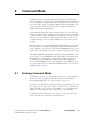
1
TM8000 mobiles
TM8100 Computer Controlled Data Interface (CCDI)
Protocol Manual
MM8100-00-00-441 Version 1.00
September 2003 © Tait Electronics Limited
Contact Information
Tait Radio Communications
http://www.taitworld.com
Corporate Head Office
New Zealand
Tait North Asia
Tait Electronics Ltd
P.O. Box 1645
Christchurch
New Zealand
E-mail: [email protected]
Website: http://www.taitworld.com
Technical Support:
E-mail: [email protected]
Website: http://support.taitworld.com
Tait North America
Regional Head Office United States of America
Tait North America Inc
E-mail: [email protected]
Regional Head Office - Hong Kong
Tait Mobile Radio (Hong Kong) Ltd
E-mail: [email protected]
Beijing
Tait Mobile Radio (Hong Kong) Ltd
E-mail: [email protected]
Tait South Asia
Regional Head Office - Singapore
Tait Electronics (Far East) Pte Ltd
E-mail: [email protected]
Thailand
Tait Mobile Radio Ltd
E-mail: [email protected]
Canada
Tait North America Inc
E-mail: [email protected]
Tait Oceania
Tait Latin America
Australia
Tait Electronics (Aust) Pty Ltd
E-mail: [email protected]
Tait Latin America
E-mail: [email protected]
Tait Europe
Regional Head Office - United Kingdom
Tait Mobile Radio Ltd
E-mail: [email protected]
2
New Zealand
Tait Communications Ltd
E-mail: [email protected]
Note: For the addresses and phone numbers
of the above regional offices refer to the
TaitWorld website.
TM8100 Computer Controlled Data Interface (CCDI) Protocol Manual
September 2003 © Tait Electronics Limited
Tait General Software Licence Agreement
This legal document is an Agreement between
you (the “Licensee”) and Tait Electronics
Limited (“Tait”). By using any of the Software
or Firmware items prior-installed in the
related Tait product, included on this CD or
downloaded from the Tait website,
(hereinafter referred to as “the Software or
Firmware”) you agree to be bound by the
terms of this Agreement. If you do not agree
to the terms of this Agreement, do not install
and use any of the Software or Firmware.
If you install and use any of the Software or
Firmware that will be deemed to be
acceptance of the terms of this licence
agreement.
The terms of this agreement shall apply
subject only to any express written terms of
agreement to the contrary between Tait and
the Licensee.
Licence
TAIT GRANTS TO YOU AS LICENSEE THE NONEXCLUSIVE RIGHT TO USE THE SOFTWARE OR
FIRMWARE ON A SINGLE MACHINE PROVIDED
YOU MAY ONLY:
1. COPY THE SOFTWARE OR FIRMWARE INTO
ANY MACHINE READABLE OR PRINTED FORM
FOR BACKUP PURPOSES IN SUPPORT OF YOUR
USE OF THE PROGRAM ON THE SINGLE MACHINE
(CERTAIN PROGRAMS, HOWEVER, MAY INCLUDE
MECHANISMS TO LIMIT OR INHIBIT COPYING,
THEY ARE MARKED “COPY PROTECTED”),
PROVIDED THE COPYRIGHT NOTICE MUST BE
REPRODUCED AND INCLUDED ON ANY SUCH
COPY OF THE SOFTWARE OR FIRMWARE;
AND / OR
2. MERGE IT INTO ANOTHER PROGRAM FOR
YOUR USE ON THE SINGLE MACHINE (ANY
PORTION OF ANY SOFTWARE OR FIRMWARE
MERGED INTO ANOTHER PROGRAM WILL
CONTINUE TO BE SUBJECT TO THE TERMS AND
CONDITIONS OF THIS AGREEMENT).
THE LICENSEE MAY NOT DUPLICATE, MODIFY,
REVERSE COMPILE OR REVERSE ASSEMBLE ANY
SOFTWARE OR FIRMWARE IN WHOLE OR PART.
Title to Software
THIS AGREEMENT DOES NOT CONSTITUTE A
CONTRACT OF SALE IN RELATION TO THE
SOFTWARE OR FIRMWARE SUPPLIED TO THE
LICENSEE. NOT WITHSTANDING THE LICENSEE
MAY OWN THE MAGNETIC OR OTHER PHYSICAL
MEDIA ON WHICH THE SOFTWARE OR
FIRMWARE WAS ORIGINALLY SUPPLIED, OR HAS
SUBSEQUENTLY BEEN RECORDED OR FIXED, IT IS
A FUNDAMENTAL TERM OF THIS AGREEMENT
THAT AT ALL TIMES TITLE AND OWNERSHIP OF
THE SOFTWARE OR FIRMWARE, WHETHER ON
THE ORIGINAL MEDIA OR OTHERWISE, SHALL
REMAIN VESTED IN TAIT OR THIRD PARTIES
WHO HAVE GRANTED LICENCES TO TAIT.
Term and Termination
THIS LICENCE SHALL BE EFFECTIVE UNTIL
TERMINATED IN ACCORDANCE WITH THE
PROVISIONS OF THIS AGREEMENT. THE LICENSEE
MAY TERMINATE THIS LICENCE AT ANY TIME BY
DESTROYING ALL COPIES OF THE SOFTWARE OR
FIRMWARE AND ASSOCIATED WRITTEN
MATERIALS. THIS LICENCE WILL BE TERMINATED
AUTOMATICALLY AND WITHOUT NOTICE FROM
TAIT IN THE EVENT THAT THE LICENSEE FAILS TO
COMPLY WITH ANY TERM OR CONDITION OF
THIS AGREEMENT. THE LICENSEE AGREES TO
DESTROY ALL COPIES OF THE SOFTWARE OR
FIRMWARE AND ASSOCIATED WRITTEN
MATERIALS IN THE EVENT OF SUCH
TERMINATION.
Limited Warranty
THE SOFTWARE OR FIRMWARE IS SUPPLIED BY
TAIT AND ACCEPTED BY THE LICENSEE “AS IS”
WITHOUT WARRANTY OF ANY KIND EITHER
EXPRESSED OR IMPLIED, INCLUDING BUT NOT
BEING LIMITED TO ANY IMPLIED WARRANTIES AS
TO MERCHANTABILITY OR FITNESS FOR ANY
PARTICULAR PURPOSE. THE LICENSEE
ACKNOWLEDGES THAT THE SOFTWARE OR
FIRMWARE IS USED BY IT IN BUSINESS AND
ACCORDINGLY TO THE MAXIMUM EXTENT
PERMITTED BY LAW NO TERMS OR WARRANTIES
WHICH ARE IMPLIED BY LEGISLATION SHALL
APPLY TO THIS AGREEMENT. TAIT DOES NOT
WARRANT THAT THE FUNCTIONS CONTAINED
IN THE SOFTWARE OR FIRMWARE WILL MEET
THE LICENSEE’S REQUIREMENTS OR THAT THE
OPERATION OF THE SOFTWARE OR FIRMWARE
WILL BE UNINTERRUPTED OR ERROR FREE.
TM8100 Computer Controlled Data Interface (CCDI) Protocol Manual
September 2003 © Tait Electronics Limited
3
Exclusion of Liability
No Other Terms
TAIT’S ENTIRE LIABILITY AND THE LICENSEE’S
EXCLUSIVE REMEDY SHALL BE THE FOLLOWING:
THE LICENSEE ACKNOWLEDGES THAT IT HAS
READ THIS AGREEMENT, UNDERSTANDS IT AND
AGREES TO BE BOUND BY ITS TERMS AND
CONDITIONS. THE LICENSEE FURTHER AGREES
THAT SUBJECT ONLY TO ANY EXPRESS WRITTEN
TERMS OF AGREEMENT TO THE CONTRARY
BETWEEN TAIT AND THE LICENSEE THIS IS THE
COMPLETE AND EXCLUSIVE STATEMENT OF THE
AGREEMENT BETWEEN IT AND TAIT IN
RELATION TO THE SOFTWARE OR FIRMWARE
WHICH SUPERSEDES ANY PROPOSAL OR PRIOR
AGREEMENT, ORAL OR WRITTEN AND ANY
OTHER COMMUNICATIONS BETWEEN THE
LICENSEE AND TAIT RELATING TO THE
SOFTWARE OR FIRMWARE.
1. IN NO CIRCUMSTANCES SHALL TAIT BE
UNDER ANY LIABILITY TO THE LICENSEE, OR
ANY OTHER PERSON WHATSOEVER, FOR ANY
DIRECT OR CONSEQUENTIAL DAMAGE ARISING
OUT OF OR IN CONNECTION WITH ANY USE OR
INABILITY OF USING THE SOFTWARE OR
FIRMWARE.
2. TAIT WARRANTS THE OPERATION OF THE
SOFTWARE OR FIRMWARE ONLY WITH THE
OPERATING SYSTEM FOR WHICH IT WAS
DESIGNED. USE OF THE SOFTWARE OR
FIRMWARE WITH AN OPERATING SYSTEM
OTHER THAN THAT FOR WHICH IT WAS
DESIGNED MAY NOT BE SUPPORTED BY TAIT,
UNLESS OTHERWISE EXPRESSLY AGREED BY
TAIT.
General
THE LICENSEE CONFIRMS THAT IT SHALL
COMPLY WITH THE PROVISIONS OF LAW IN
RELATION TO THE SOFTWARE OR FIRMWARE.
Law and Jurisdiction
THIS AGREEMENT SHALL BE SUBJECT TO AND
CONSTRUED IN ACCORDANCE WITH
NEW ZEALAND LAW AND DISPUTES BETWEEN
THE PARTIES CONCERNING THE PROVISIONS
HEREOF SHALL BE DETERMINED BY THE NEW
ZEALAND COURTS OF LAW. PROVIDED HOWEVER
TAIT MAY AT ITS ELECTION BRING PROCEEDINGS
FOR BREACH OF THE TERMS HEREOF OR FOR
THE ENFORCEMENT OF ANY JUDGEMENT IN
RELATION TO A BREACH OF THE TERMS HEREOF
IN ANY JURISDICTION TAIT CONSIDERS FIT FOR
THE PURPOSE OF ENSURING COMPLIANCE WITH
THE TERMS HEREOF OR OBTAINING RELIEF FOR
BREACH OF THE TERMS HEREOF .
No Dealings
THE LICENSEE MAY NOT SUBLICENSE, ASSIGN OR
TRANSFER THE LICENCE OR THE PROGRAM
EXCEPT AS EXPRESSLY PROVIDED IN THIS
AGREEMENT. ANY ATTEMPT OTHERWISE TO
SUBLICENSE, ASSIGN OR TRANSFER ANY OF THE
RIGHTS, DUTIES OR OBLIGATIONS HEREUNDER
IS VOID.
4
TM8100 Computer Controlled Data Interface (CCDI) Protocol Manual
September 2003 © Tait Electronics Limited
Contents
1
Introduction . . . . . . . . . . . . . . . . . . . . . . . . . . . . . . . . . . . . . . . . . . 11
1.1 Serial Ports . . . . . . . . . . . . . . . . . . . . . . . . . . . . . . . . . . . . . . . . . . . . . . . 12
Auxiliary Connector. . . . . . . . . . . . . . . . . . . . . . . . . . . . . . . . . . . . . . 12
Microphone Connector . . . . . . . . . . . . . . . . . . . . . . . . . . . . . . . . . . . 14
Data Characteristics . . . . . . . . . . . . . . . . . . . . . . . . . . . . . . . . . . . . . . 14
Logic Level Compatibility. . . . . . . . . . . . . . . . . . . . . . . . . . . . . . . . . . 15
1.2 Before Operating . . . . . . . . . . . . . . . . . . . . . . . . . . . . . . . . . . . . . . . . . . 15
1.3 Limitations . . . . . . . . . . . . . . . . . . . . . . . . . . . . . . . . . . . . . . . . . . . . . . . 16
2
Radio Programming . . . . . . . . . . . . . . . . . . . . . . . . . . . . . . . . . . . . 17
2.1 Data form . . . . . . . . . . . . . . . . . . . . . . . . . . . . . . . . . . . . . . . . . . . . . . . . 17
Software Flow Control . . . . . . . . . . . . . . . . . . . . . . . . . . . . . . . . . . . . 17
CCDI Options . . . . . . . . . . . . . . . . . . . . . . . . . . . . . . . . . . . . . . . . . . 18
Data. . . . . . . . . . . . . . . . . . . . . . . . . . . . . . . . . . . . . . . . . . . . . . . . . . 18
SDM Options . . . . . . . . . . . . . . . . . . . . . . . . . . . . . . . . . . . . . . . . . . 19
Data Flow . . . . . . . . . . . . . . . . . . . . . . . . . . . . . . . . . . . . . . . . . . . . . 19
3
Transparent Mode . . . . . . . . . . . . . . . . . . . . . . . . . . . . . . . . . . . . . . 21
3.1 Entering Transparent Mode . . . . . . . . . . . . . . . . . . . . . . . . . . . . . . . . . . . 21
3.2 Transparent Mode Format . . . . . . . . . . . . . . . . . . . . . . . . . . . . . . . . . . . . 22
Transparent Mode Packetisation . . . . . . . . . . . . . . . . . . . . . . . . . . . . . 22
FFSK Transmission Format . . . . . . . . . . . . . . . . . . . . . . . . . . . . . . . . . 22
Effective Over-Air Data Rate . . . . . . . . . . . . . . . . . . . . . . . . . . . . . . . 23
Lead-In Delay . . . . . . . . . . . . . . . . . . . . . . . . . . . . . . . . . . . . . . . . . . 23
3.3 XON/XOFF Software Flow Control . . . . . . . . . . . . . . . . . . . . . . . . . . . 24
4
Command Mode . . . . . . . . . . . . . . . . . . . . . . . . . . . . . . . . . . . . . . . 27
4.1 Entering Command Mode. . . . . . . . . . . . . . . . . . . . . . . . . . . . . . . . . . . . 27
4.2 CCDI Command Format . . . . . . . . . . . . . . . . . . . . . . . . . . . . . . . . . . . . 28
4.3 Calculating the CCDI [CHECKSUM]. . . . . . . . . . . . . . . . . . . . . . . . . . . 29
Checksum Example . . . . . . . . . . . . . . . . . . . . . . . . . . . . . . . . . . . . . . 29
4.4 Commands to the TM8100 . . . . . . . . . . . . . . . . . . . . . . . . . . . . . . . . . . . 30
DIAL. . . . . . . . . . . . . . . . . . . . . . . . . . . . . . . . . . . . . . . . . . . . . . . . . 31
GO_TO_CHANNEL . . . . . . . . . . . . . . . . . . . . . . . . . . . . . . . . . . . . 32
CANCEL . . . . . . . . . . . . . . . . . . . . . . . . . . . . . . . . . . . . . . . . . . . . . 32
FUNCTION . . . . . . . . . . . . . . . . . . . . . . . . . . . . . . . . . . . . . . . . . . . 33
QUERY . . . . . . . . . . . . . . . . . . . . . . . . . . . . . . . . . . . . . . . . . . . . . . 34
TRANSPARENT . . . . . . . . . . . . . . . . . . . . . . . . . . . . . . . . . . . . . . . 35
SEND_SDM . . . . . . . . . . . . . . . . . . . . . . . . . . . . . . . . . . . . . . . . . . . 36
4.5 Messages from the TM8100. . . . . . . . . . . . . . . . . . . . . . . . . . . . . . . . . . . 37
ERROR . . . . . . . . . . . . . . . . . . . . . . . . . . . . . . . . . . . . . . . . . . . . . . 38
TM8100 Computer Controlled Data Interface (CCDI) Protocol Manual
September 2003 © Tait Electronics Limited
5
MODEL . . . . . . . . . . . . . . . . . . . . . . . . . . . . . . . . . . . . . . . . . . . . . .
RING . . . . . . . . . . . . . . . . . . . . . . . . . . . . . . . . . . . . . . . . . . . . . . . .
PROGRESS . . . . . . . . . . . . . . . . . . . . . . . . . . . . . . . . . . . . . . . . . . .
GET_SDM . . . . . . . . . . . . . . . . . . . . . . . . . . . . . . . . . . . . . . . . . . . .
6
39
40
41
43
TM8100 Computer Controlled Data Interface (CCDI) Protocol Manual
September 2003 © Tait Electronics Limited
Preface
Scope of Manual
This manual contains reference information about the TM8100 CCDI
protocol.
Enquiries and Comments
If you have any enquiries regarding this manual, or any comments,
suggestions and notifications of errors, please contact support at one of the
addresses listed on page 2).
Updates of Manual and Equipment
In the interests of improving the performance, reliability or servicing of the
equipment, Tait Electronics Ltd reserves the right to update the equipment
or this manual or both without prior notice.
Copyright
All information contained in this manual is the property of
Tait Electronics Ltd. All rights are reserved. This manual may not, in whole
or in part, be copied, photocopied, reproduced, translated, stored, or
reduced to any electronic medium or machine-readable form, without prior
written permission from Tait Electronics Ltd.
All trade names referenced are the service mark, trademark or registered
trademark of the respective manufacturers.
Disclaimer
There are no warranties extended or granted by this manual.
Tait Electronics Ltd accepts no responsibility for damage arising from use of
the information contained in the manual or of the equipment and software
it describes. It is the responsibility of the user to ensure that use of such
information, equipment and software complies with the laws, rules and
regulations of the applicable jurisdictions.
TM8100 Computer Controlled Data Interface (CCDI) Protocol Manual
September 2003 © Tait Electronics Limited
7
Associated Documentation
TM8100 Mobile Radio User’s Guide (MM8100-00-03-804)
TM8100 Mobile Radio Service Manual (MM8100-00-00-812)
TM8000 Mobile Radio Accessories Manual (MMAA00-00-00-812)
TM8000 3DK Hardware Developer’s Kit Application Manual
(MMAA30-01-00-807
TM8000 3DK Resource CD (TMAA30-01)
TMAA30-02 TM8000 3DK Application Board Service Manual
(MMAA30-02-00-812)
TMAA30-02 TM8000 3DK Application Board Software Manual
(MMAA30-02-00-429)
Publication Record
Issue
Publication Date
1
September 2003
Description
new manual
Alert Notices
Within this manual, three types of alerts are given to the reader: warning,
important and note. The following paragraphs illustrate each type of alert
and its associated symbol.
Warning!!
This alert is used when there is a potential risk
of death or serious injury.
Caution
This alert is used when there is the risk of minor or
moderate injury to people.
Important
This alert is used to warn about the risk of equipment damage or malfunction.
Note
8
This alert is used to highlight information that is required to
ensure that procedures are performed correctly.
TM8100 Computer Controlled Data Interface (CCDI) Protocol Manual
September 2003 © Tait Electronics Limited
Abbreviations
Abbreviation
Description
3DK
Third-Party Developer’s Kit
ASCII
American Standard Code for Information Interchange
CCDI
Computer Controlled Data Interface
CRC
Cyclic Redundancy Check
CTCSS
Continuous Tone Coded Squelch System
CTS
Clear to Send
DCS
Data Carrier System
DTE
Data Terminal Equipment
DTMF
Dual Tone Multi-Frequency
FFSK
Fast Frequency Shift Keying
GPIO
General Purpose Input/Output
IPN
Internal Part Number
LED
Light-Emitting Diode
MSD
Most Significant Digit
PC
Personal Computer
PTT
Press To Talk
RTS
Request to Send
Rx
Receive
RXD
Receive Data
SDM
Short Data Message
Tx
Transmit
TXD
Transmit Data
UART
Universal Asynchronous Receiver-Transmitter
XON
Transmitter On
XOFF
Transmitter Off
TM8100 Computer Controlled Data Interface (CCDI) Protocol Manual
September 2003 © Tait Electronics Limited
9
10
TM8100 Computer Controlled Data Interface (CCDI) Protocol Manual
September 2003 © Tait Electronics Limited
1
Introduction
The Computer Controlled Data Interface (CCDI) protocol is a Tait
proprietary command protocol embedded in the TM8100 and used for
communicating with the TM8100 via asynchronous serial ports.
The TM8100 is the DCE (Data Circuit-Terminating Equipment) and is
connected directly to the DTE (Data Terminal Equipment), usually a PC,
via the serial port.
Two modes of operation are available using the serial ports:
■
Command mode
■
Transparent mode
PC running
terminal application
PC running
terminal application
PC Serial Port
PC Serial Port
FI
F4
F2
F3
TM8000 radio
FI
F4
F2
F3
TM8000 radio
When in Command mode, commands and response messages are passed
between the PC and the TM8100 using the CCDI protocol. The
Command mode baud rate is selectable using the TM8000 Programming
Application to either 1200, 2400, 4800, 9600, 14400 or 19200 baud.
When in Transparent mode, communication between the PC and the
TM8100 is Fixed Frequency Shift Keying (FFSK) data and is selectable using
the TM8000 Programming Application to either 1200, 2400, 4800, 9600,
14400 or 19200 baud.
The over-air data rate is always fixed at 1200 bps for FFSK data.
CCDI2 refers to CCDI version 2.XX.
TM8100 Computer Controlled Data Interface (CCDI) Protocol Manual
September 2003 © Tait Electronics Limited
Introduction
11
1.1
Serial Ports
There are three ports available for CCDI asynchronous serial
communication with the TM8100. The microphone and auxiliary ports are
accessed externally, and the internal options connector is internal to the
radio.
Only one of these ports can be used for CCDI transmission and reception
at any time and the port is selected in the Data form of the TM8000
Programming Application. Select “Mic”, “Aux” or “Internal Connector”.
1.1.1
■
Mic: the radio will transmit and receive data via the MIC_TXD and
MIC_RXD lines on the microphone connector. Refer to “Microphone
Connector” for signal details.
■
Aux: the radio will transmit and receive data via the AUX_TXD and
AUX_RXD lines on the auxiliary connector. Refer to “Auxiliary
Connector” for signal details.
■
Internal Connector: the radio will transmit and receive data via the
IOP_TXD and IOP_RXD lines on the internal options connector. This
connector is used to fit an internal options board into the TM8100.
Refer to the TM8000 3DK Hardware Developer’s Kit Application
Manual for more details.
Auxiliary Connector
The auxiliary connector is the standard interface for external devices that are
typically connected to a radio. The auxiliary connector is a 15-way standarddensity D-range socket. The auxiliary connector provides a serial port, three
programmable input lines, four programmable digital I/O lines and audio
I/O. The AUX_TXD and AUX_RXD lines are used to transmit and
receive data from the radio.
Note
The space for a mating plug is limited to 41mm in width and
18mm in height. Although most plugs will fit this space, it is recommended that you test the plug to be used before manufacturing
a cable. The internal options kit available from Tait includes a suitable plug (Tait IPN 240-00020-55).
If the auxiliary cable is longer than 1 metre, it is recommended that the cable
and connector backshell be shielded. The diagram shows the recommended
shielding arrangement. The earth braid wire (bare copper) and aluminium
foil should only be earthed at the radio end of the cable.
12
Introduction
TM8100 Computer Controlled Data Interface (CCDI) Protocol Manual
September 2003 © Tait Electronics Limited
metal D-range shroud in
contact with backshell
metal backshell
signal earth wire
cable insulation
aluminium foil
metal cable clamp
earth braid wire
analogue ground pin
Pinout
Pin
B
C
D
E
F
G
H
I
J
1)
1!
1@
1#
1$
1%
rear view
Signal name
12
AUX_GPI1
5
AUX_GPI2
4
AUX_GPI3
10
2
9
1
11
3
7
13
14
6
8
15
AUX_GPIO4
AUX_GPIO5
AUX_GPIO6
AUX_GPIO7
AUX_TXD
Description
General purpose digital input.
Programmable function.
General purpose digital input.
Programmable function.
With LK3 fitted, GPI2 is an
emergency power sense input.
General purpose digital input.
Programmable function.
With LK2 fitted, GPI3 is a power
sense input.
Programmable function and
direction.
Pads available to fit a higher power
driver transistor on GPIO4 line.
Asynchronous serial port Transmit data
AUX_RXD
Asynchronous serial port Receive data
AUD_TAP_IN
Programmable tap point into the Rx
or Tx audio chain. DC-coupled.
AUD_TAP_OUT Programmable tap point out of the
Rx or Tx audio chain. DC-coupled.
AUX_MIC_AUD Auxiliary microphone input.
Electret microphone biasing
provided. Dynamic microphones are
not supported.
RSSI
Analogue RSSI output.
+13V8_SW
Switched 13.8V supply. Supply is
switched off when radio body is
switched off.
AGND
Analogue ground
Signal type
Digital. 3V3 CMOS.
Digital. 3V3 CMOS.
Digital. 3V3 CMOS.
Digital.
3V3 CMOS input.
Open collector
output with pullup.
Digital. 3V3 CMOS.
Digital. 3V3 CMOS.
Analogue.
Analogue.
Analogue.
Analogue.
Power.
Ground.
Refer to the TM8000 3DK Hardware Developer’s Kit Application Manual
for more details about the auxiliary connector.
TM8100 Computer Controlled Data Interface (CCDI) Protocol Manual
September 2003 © Tait Electronics Limited
Introduction
13
1.1.2
Microphone Connector
The microphone connector on the TM8100 control head is an RJ-45
socket.
When the TM8100 control head is connected to the control-head
connector of the radio body using the loom provided, the microphone
connector uses the following eight control-head connector signals:
Pinout
Pin
Signal name
Description
Signal type
1
MIC_RX_AUD
Receive audio output.
Analogue
B
2
+13V8_SW
Power supply output. Switched off
when radio body is switched off.
Power
I
3
MIC_TXD
Asynchronous serial port Transmit data.
3.3V CMOS
4
MIC_PTT
PTT input from microphone.
Also carries hookswitch signal.
Digital
5
MIC_AUD
Fist microphone audio input.
Analogue
6
AGND
Analog ground.
Analogue ground
7
MIC_RXD
Asynchronous serial port Receive data.
3.3V CMOS
8
MIC_GPIO1
General purpose digital input/
output.
Open collector out
3.3V CMOS in
front view
The MIC_TXD and MIC_RXD lines are used to transmit and receive data
from the radio. Refer to the TM8000 3DK Hardware Developer’s Kit
Application Manual for more details about the microphone connector.
1.1.3
Data Characteristics
Standard
Parameter
Comments
min.
typ.
max.
units
Serial port
Baud rate:
1200, 2400, 4800,
9600, 14400, 19200
Data bits:
8
Start bit:
1
Stop bit:
1
Parity:
None
Protocol:
CCDI2
Flow control:
Software
XON/XOFF
bit/s
All UART parameters are
fixed and common to all
UARTs except for the baud
rate which is configurable
and different for different
modes/applications
GPIO
Delays:
I/O mirror to IOP
UI key delay
14
Introduction
500
50
µs
ms
TM8100 Computer Controlled Data Interface (CCDI) Protocol Manual
September 2003 © Tait Electronics Limited
1.1.4
Logic Level Compatibility
The following table show the compatibility of the TM8000 digital I/O used
for CCDI with common industry logic standards.
Digital Input
Compatibility and
Tolerance
Logic standard input compatibility and tolerance
Digital Input
Line
3.3V CMOS
5V TTL
RS-232
AUX_RXD
Yes
Yes
Yes
Yes
IOP_RXD
Yes
Yes
Yes
Noa
CH_RXD
MIC_RXD
PRG_RXD
Yes
Yes
Yes
Yes
a.
Level compatible but not tolerant. Inputs can be made RS-232 tolerant
by using 3.3kOhm series resistance inserted at the radio end.
Digital Output
Compatibility
Logic standard input compatibility and tolerance
Digital Output
Line
3.3V CMOS
5V CMOS
5V TTL
RS-232
AUX_TXD
Yes
No
Yes
No
IOP_TXD
Yes
Noa
Yes
No
CH_TXD
MIC_TXD
PRG_TXD
Yes
No
Yes
No
a.
1.2
5V CMOS
These outputs can be made 5V CMOS compatible using a 3.3k Ohm
pull-up resistor to 5V that is provided by the device being driven.
Before Operating
Before using CCDI, the following may be useful to check.
■
The radio must be correctly programmed for use with the CCDI
protocol. See “Radio Programming” on page 17 for configuration
information.
■
At power on, the radio will select its default channel. To change the
channel, select the channel using the normal radio interface or using the
CCDI Go_to_Channel command (see “GO_TO_CHANNEL” on
page 32).
Note that some channels are designated data channels in the Details tab
of the Channels form which means they are optimised for data.
■
The radio will power on into the mode selected in the ‘Powerup State’
field in the Data form.
■
Power, Tx and Rx LED indicators are helpful for establishing proper
operation. The radio speaker can be used to listen to data coming in.
TM8100 Computer Controlled Data Interface (CCDI) Protocol Manual
September 2003 © Tait Electronics Limited
Introduction
15
■
Data flow is controlled either by the customer’s embedded computer
system or by a PC running a data-sending application such as
Hyperterminal.
Note
1.3
In accordance with RS-232 specifications, the radio should be
within 15m of the computer equipment for optimum performance.
Limitations
Important
16
Introduction
Some data applications require extended transmission
times. This may be for larger file transfers or for real-time
telemetry information. This may put undue stress on the
radio transmitter and care must be taken to control transmission times using flow control. See “XON/XOFF Software Flow Control” on page 24.
TM8100 Computer Controlled Data Interface (CCDI) Protocol Manual
September 2003 © Tait Electronics Limited
2
Radio Programming
This section describes how to configure the TM8100 radio using the
TM8000 programming application, for use with CCDI and data.
2.1
Data form
The Data form is used for setting up the majority of the parameters affecting
data.
2.1.1
Software Flow Control
Software Flow Control assigns the XON and XOFF characters used for
software handshaking. See “XON/XOFF Software Flow Control” on
page 24.
Software Flow Control is only enabled when the flow control is set to
‘Software’ in the Data Flow section of the Data form in the TM8100
Programming Application. The type of flow control is applied to each mode
independently, although flow control has no affect in Command mode as
commands are generally smaller than the input buffer.
TM8100 Computer Controlled Data Interface (CCDI) Protocol Manual
September 2003 © Tait Electronics Limited
Radio Programming
17
2.1.2
CCDI Options
Transparent Mode
Enabled
If this is enabled, the radio is able to enter Transparent mode. See
“Transparent Mode” on page 21 for more information.
CCDI UART Port
Specifies the UART port to be used for CCDI transmission and reception.
‘Internal Connector’ means that data will flow via the internal options
connector using the IOP-TXD and IOP_RXD lines.
‘Mic’ means that data will flow via the front panel serial interface
(microphone connector) using the MIC_TXD and MIC_RXD lines.
’Aux’ means that data will flow via the auxiliary serial interface (rear
auxiliary connector) using the AUX_TXD and AUX_RXD lines.
2.1.3
Data
Lead In Delay
The Lead-In Delay begins after the transmitter key-up time. It gives the
receiver at the other end time to open before data is sent.
Set the Lead-In Delay to a suitable value depending on flow control settings
and subaudible signalling and data requirements. See “Lead-In Delay” on
page 23 for more information.
Lead-Out Delay
The Lead-Out Delay is the time that the transmitter stays keyed-up after a
data block is sent. This parameter is sometimes know as the Tail Time.
Ignore DCS/CTCSS
This option applies to all FFSK Transparent mode and SDM data
transmissions. It is only relevant if the current channel is programmed for
subaudible signalling.
Leave this option unchecked if you want the radio to only process over-air
data that is accompanied by valid subaudible signalling.
Checking this option will deactivate validation of CTCSS and DCS
subaudible signalling. This means that when the TM8100 receives data, it
will be processed regardless of the subaudible signalling. The advantage of
this is faster decoding of the incoming data, as subaudible signalling does not
require decoding.
The default radio setting at power on is set by this option. The CCDI
Function command can be used after power on to change subaudible signal
decoding. See “FUNCTION” on page 33.
18
Radio Programming
TM8100 Computer Controlled Data Interface (CCDI) Protocol Manual
September 2003 © Tait Electronics Limited
2.1.4
SDM Options
SDM Enable
Must be checked for the TM8100 to send and receive Short Data Messages
(SDMs).
SDM Auto
Acknowledge
If checked, an SDM Auto Aknowledge is sent by the radio to the PC, when
it receives an SDM.
SDM Auto
Acknowledge Delay
Sets the delay between receiving an SDM and sending an Auto
Acknowledge, if configured to do so.
SDM Wait For
Acknowledge
The maximum time that the radio will wait for an Auto Acknowledge
before sending a Progress message to say that no SDM Auto Acknowledge
was received.
Unit Data Identity
Sets the radio’s identity for operation in CCDI mode. Enter an identity of 8
characters from A to Z, 0 to 9 or the wildcard character *.
2.1.5
Data Flow
Powerup State
Determines the data state the radio defaults to at power on. We recommend
that this field is set to “C-Mode” (Command Mode) so that the radio will
be in Command mode at power on. Set to “T-Mode” for Transparent
mode.
Ignore Escape
Sequence in T-Mode
If this field is checked, the radio will ignore all incoming escape sequences
instructing it to exit Transparent mode and change to Command mode. We
recommend that this field is unchecked.
Baud Rate
Determines the data transfer rate in bits per second (bps) between radio and
computer equipment.
Note that the over-air data rate is always 1200 bps for FFSK data and
selecting higher baud rates requires Flow Control to be enabled unless the
amount of data per transmission is restricted to 100 bytes or less.
TM8100 Computer Controlled Data Interface (CCDI) Protocol Manual
September 2003 © Tait Electronics Limited
Radio Programming
19
20
Radio Programming
TM8100 Computer Controlled Data Interface (CCDI) Protocol Manual
September 2003 © Tait Electronics Limited
3
Transparent Mode
In Transparent mode, the radio acts as a modem, automatically transmitting
in FFSK format the serial data received from the PC. In this mode, the baud
rate between the PC (DTE) and the radio (DCE) can be set to either 1200,
2400, 4800, 9600, 14400 or 19200 baud using the TM8000 Programming
Application. The over-air data rate is always fixed at 1200 bps for FFSK data.
The TM8100 serial data input buffer is 128 bytes to adequately cope with
the data flow.
CTCSS and DCS subaudible signalling is available in Transparent mode but
other programmable features such as Selcall and DTMF are unavailable.
Communication in Transparent mode is free-format, with the protocol
determined entirely by the PC and the modem. It is transparent to the
CCDI, allowing the PC to send and receive data without passing through
CCDI.
If an SDM is received in Transparent mode, it is tested for SDM validity by
checking the leading ‘s’, the checksum, the SDM identity and the size. If it
is found to be a valid SDM, it is saved in the SDM buffer for later retrieval.
3.1
Entering Transparent Mode
Transparent mode can be set as the default mode at power on by selecting
“T-Mode” in the ‘Powerup State’ field in the Data form of the TM8000
Programming Application. See “Powerup State” on page 19.
To change to Transparent mode while operating in Command mode, the
PC must send a TRANSPARENT command to the radio. E.g. t01zB1
sends a TRANSPARENT command, requesting that the radio be put into
Transparent mode. The escape character specified here is “z” (ASCII code
= $7A). Once acknowledged, any further data is linked directly to the radio
in Transparent mode.
If the radio default is set to Transparent mode at power on, the default escape
character is “+”.
TM8100 Computer Controlled Data Interface (CCDI) Protocol Manual
September 2003 © Tait Electronics Limited
Transparent Mode
21
3.2
Transparent Mode Format
3.2.1
Transparent Mode Packetisation
over-air
no Flow Control
TM8000 radio
PC
data
RS232
TM8000 radio
FFSK-OUT
FFSK-OUT
FFSK-IN
FFSK-IN
processing...
processing...
SER-OUT
SER-OUT
SER-IN
SER-IN
data
RS232
PC
time...
Flow
Control
data block 1
Lead-In
Delay
Flow
Control
data block n
Lead-Out
Delay
Transparent mode data is packetised into data blocks before it is sent overair. The start and stop bits are removed and a header is sent at the start of
each data block.
3.2.2
FFSK Transmission Format
The Transparent Mode transmission format is as follows:
Singe Data Block
LID
preamble
2 bytes
sync
2 bytes
size
2 bytes
H E
A D E R
HEADER
6 bytes
FFSK data block
max 46 bytes
FFSK data block
max 46 bytes
CRC
2 bytes
(00)
Tail Time
Multiple Data
Blocks
LID
22
Transparent Mode
............
HEADER
6 bytes
FFSK data block
max 46 bytes
CRC
2 bytes
(00)
Tail Time
TM8100 Computer Controlled Data Interface (CCDI) Protocol Manual
September 2003 © Tait Electronics Limited
3.2.3
Effective Over-Air Data Rate
Data rate varies depending on the quantity of data. For example, assuming
460 byte data is being sent, with a Lead-In Delay of 100ms and Lead-Out
Delay of 20ms, the effective data rate is calculated below. Note that these
calculations are theoretical only as there are other real-life factors not being
considered.
460 bytes /46 bytes per data block = 10 data blocks
Bytes sent:
2 bytes preamble + 2 sync + 2 size + 2 CRC = 8 bytes for Header and CRC
per data block
8 bytes overhead x 10 data blocks = 80 total overhead bytes
460 bytes of data + 80 bytes overhead = 540 total bytes sent
540 bytes sent x 10 bits per bytes = 5400 bits
5400 - 1080 (start and stop bits removed) = 4320 bits sent over-air
Time taken:
4320 / 1200 = 3.6 seconds time to send bits
3.6 seconds + 120 ms = 3.72 seconds including Lead-In and Lead-Out
Delay
Data Rate
(effective):
460 bytes x 8 bits = 3680 bits to be sent
3680 bits / 3.72 seconds = 989 bits / second
Note
3.2.4
If 461 bytes are sent, then the number of data blocks rounds up to
11. This reduces the effective data rate significantly to 915 bits /
second.
Lead-In Delay
The Lead-In Delay begins after the transmitter key-up time. It gives the
receiver(s) at the other end time to open before data is sent.
carrier
Tx
Lead-In
Delay
data
Lead-Out
Delay
Tx
Key-up
Tx
Key-down
time
When data is detected at the TM8100 input buffer, the following occurs:
TM8100 Computer Controlled Data Interface (CCDI) Protocol Manual
September 2003 © Tait Electronics Limited
Transparent Mode
23
■
The transmitter keys up.
■
A carrier is sent from the transmitter. When the carrier reaches its full
potential, the Lead-In Delay begins.
■
If the receiving base station is set to Repeater mode, the carrier is
detected and Rx Gate becomes active (opens), which in turn makes the
PTT line active.
■
The active PTT line keys up the transmitter.
This sequence is repeated with as many base stations as are in the chain. The
optimum length of the Lead-In Delay should be set keeping in mind the
number of Base Stations that need to be activated before any data is sent.
The Lead-In Delay must also allow for subaudible signalling decoding, if it
is enabled, when used in conjunction with FFSK data.
3.3
XON/XOFF Software Flow Control
XON/XOFF software handshaking is used for flow control in Transparent
mode and becomes active when the data flow is set for software flow control.
This is set in the Data Flow section of the Data form of the TM8000
Programming Application. See “Software Flow Control” on page 17.
The XOFF character is sent to the PC:
■
when the serial input data buffer has reached approximately 2/3 of its 128
byte capacity.
The XON character is sent to the PC:
■
after the XOFF character has been sent and then the serial input data
buffer becomes empty
■
when entering Transparent mode if the channel is not busy
The data rate is set depending on the value set by the Transparent mode
Baud Rate set in the Data form. Since the over-air FFSK data is transmitted
or received at 1200 baud regardless, if the radio is set to a higher baud rate
than 1200 baud, XON/XOFF software handshaking must be used
otherwise some part of the data stream will be lost.
If 1200 baud is selected as the Transparent mode baud rate and the Lead-In
Delay is short (less than 300 ms) in Transparent mode, XON/XOFF
software handshaking is not necessary. Even if higher baud rates are used, as
long as the data throughput rate is slow enough (less than 40 bytes in one
transmission) then XON/XOFF is not necessary, assuming the Lead-In
Delay is short enough.
24
Transparent Mode
TM8100 Computer Controlled Data Interface (CCDI) Protocol Manual
September 2003 © Tait Electronics Limited
Important
When using XON/XOFF software handshaking, the data
stream (or the data file) must not include the programmed
XON and XOFF characters. If these characters are received
by the PC of the receiving radio, there is no way to differentiate between data and XON/XOFF characters.
ASCII text files or data work well with XON/XOFF flow control but
binary files or data may have problems. When sending and receiving binary
files or data, 1200 baud rate must be selected in the Transparent mode. If the
Lead-In Delay is programmed longer than 300 ms with 1200 baud selected,
XON/XOFF flow control must be used, otherwise some data in the initial
part may be lost.
Note
Communication standards typically set XON = [CTRL] Q = 11
Hex; XOFF = [CTRL] S = 13 Hex; XON/XOFF values must
are set in the Data form of the TM8000 Programming Application.
TM8100 Computer Controlled Data Interface (CCDI) Protocol Manual
September 2003 © Tait Electronics Limited
Transparent Mode
25
26
Transparent Mode
TM8100 Computer Controlled Data Interface (CCDI) Protocol Manual
September 2003 © Tait Electronics Limited
4
Command Mode
Command mode uses the Tait proprietary Computer Controlled Data
Interface (CCDI), a command protocol embedded in the radio firmware. It
is accessed using the serial port lines from the PC. In this mode, the baud
rate between the computer equipment (DTE) and the radio (DCE) can be
set to either 1200, 2400, 4800, 9600, 14400 or 19200 baud using the
TM8000 Programming Application
In Command mode, the PC sends command sequences to the radio and
waits for a prompt before beginning the next transaction. Some commands
require the radio to send a CCDI message in response, before the prompt
character ‘.’ is sent to the PC to indicate that it is ready to accept a new
command. Messages sent to the radio will always be responded to by the
prompt.
Unsolicited messages such as PROGRESS or ERROR messages are sent by
the radio if there is a significant change in its state that the PC should be
aware of. When errors are detected, an unsolicited ERROR message is sent
by the radio to the PC. The radio cannot send messages that require a reply.
The SEND_SDM and GET_SDM commands require that SDMs are sent
and received as over-air FFSK data by the radio while in Command mode.
If an SDM is received from the over-air interface while the radio is in
Command mode, the SDM data is buffered and both an ‘FFSK Data
Received’ PROGRESS message and a ‘SDM Received’ RING messages
are generated by the radio to indicate that SDM data has been received. See
“SEND_SDM” on page 36.
4.1
Entering Command Mode
Command mode can be set as the default mode at power on by selecting CMode in the ‘Powerup State’ field in the Data form of the TM8000
Programming Application. See “Powerup State” on page 19.
To change to Command mode while operating in Transparent mode, send
the escape sequence. The escape sequence consists of a 2 second idle time,
followed by three escape characters (sent within 2 seconds), followed by a
further 2 second idle time i.e. [2 second idle] +++ [2 second idle].
In Transparent mode, when the escape sequence is detected in the data
stream, the radio is forced back to Command mode.
TM8100 Computer Controlled Data Interface (CCDI) Protocol Manual
September 2003 © Tait Electronics Limited
Command Mode
27
4.2
CCDI Command Format
The Tait Computer Controlled Data Interface (CCDI) protocol provides
the means of controlling a TM8100 from a PC, to allow either a semi- or
fully automatic communications system. CCDI is embedded in the radio
software, and accessed via the serial lines on the programming lead between
the PC and the TM8100.
Note
What is transmitted over-air is an analogue version of CCDI suitable for RF.
All CCDI message packets take the general form:
[IDENT] [SIZE] [PARAMETERS] [CHECKSUM] <CR>
Restrictions
28
Command Mode
■
[IDENT] = The message identifier. Identifiers are single ASCII
characters (lower-case alphabetical) which categorise the message type.
■
[SIZE] = The number of characters which make up the
[PARAMETERS] field. [SIZE] is an 8-bit number expressed in ASCII
hex notation (two characters).
■
[PARAMETERS] = An optional field, depending upon the command.
Parameter values are generally character strings unless explicitly stated
otherwise. Parameter type is dependent upon the command, and often
has multiple parts.
■
[CHECKSUM] = An 8-bit checksum of the [IDENT], [SIZE] and
[PARAMETERS] fields. Expressed in two character ASCII hex
notation.
■
<CR> = The carriage return packet terminator.
■
All characters in a message are printable ASCII.
■
Where numeric values are represented in ASCII hex notation (two
characters per byte), characters A to F are upper case.
■
The minimum length of a command packet is 5 characters. For example
q002F is the QUERY command where [SIZE] = 00 as there is no
[PARAMETERS] field required.
■
The maximum length of the [PARAMETERS] field is 42 characters.
The maximum length of the command packet is therefore 47 characters.
TM8100 Computer Controlled Data Interface (CCDI) Protocol Manual
September 2003 © Tait Electronics Limited
4.3
Calculating the CCDI [CHECKSUM]
[CHECKSUM] is calculated by applying the following algorithm:
4.3.1
1.
Take the modulo-2 sum of all message bytes preceding [CHECKSUM].
2.
Retain bits 0 to 7, discarding any higher order bits resulting from the
summation.
3.
Form the two’s complement of the remainder.
4.
Convert the binary number into two ASCII hex digits, MSD first.
Checksum Example
s0D050800TESTHi!DA
1.
Take the modulo-2 sum of all message bytes preceding [CHECKSUM].
■
s = 73h, 0 = 30h, D = 44h etc. therefore the modulo-2 sum is:
73 + 30 + 44 + 30 + 35 + 30 + 38 + 30 + 30 + 54 + 45 + 53 +
54 + 48 + 69 + 21 = 426h
2.
Retain bits 0 to 7, discarding any higher order bits resulting from the
summation.
26h
3.
Form the two’s complement of the remainder.
26h = 0010 0110
two’s complement = 1101 1010
4.
Convert the binary number into two ASCII hex digits, MSD first.
1101 1010 = DA
TM8100 Computer Controlled Data Interface (CCDI) Protocol Manual
September 2003 © Tait Electronics Limited
Command Mode
29
4.4
Commands to the TM8100
The following commands are available to send from the PC to control the
radio.
Command
IDENT
Function
DIAL
d
initiate a call
GO_TO_CHANNEL
g
sets the radio to a particular channel
CANCEL
c
abort current activities
FUNCTION
f
controls various hardware and miscellaneous
radio functions
QUERY
q
requests information from the radio
TRANSPARENT
t
change to transparent mode
SEND_SDM
s
send a Short Data Message (SDM)
In all cases, if a command is received without error by the TM8100 and all
parameters are valid, the command is executed. The prompt character ‘.’ is
then returned to the PC after the TM8100 completes the current
transaction, to signify that another may begin. If an error arises, the PC is
notified with an appropriate ERROR response.
30
Command Mode
TM8100 Computer Controlled Data Interface (CCDI) Protocol Manual
September 2003 © Tait Electronics Limited
4.4.1
DIAL
The DIAL command allows access to the full dialling capability of the radio.
Selcall and DTMF sequences can be dialled on the current channel. It has
the format:
d [SIZE] [DTYPE] [NUMBER_STR] [CHECKSUM]
■
‘ d ‘ is sent as a single ASCII character and represents the DIAL
command.
■
[DTYPE] is a single ASCII character representing the type of dialling
required.
[DTYPE]
Function
0
Selcall
1
DTMF
2
Reserved for Trunked radio dialling
■
[NUMBER_STR] represents the dialled sequence. The range of allowed
characters depends upon the value of [DTYPE].
[DTYPE]
[NUMBER_STR]
0
(Selcall)
0...9, A...F, -, V (maximum of 32 digits).
Selcall strings usually use the digits 0 to 9 as some of the tones A to F
have special meaning, e.g. A = Group; C = Reset; E = Repeat.
Selcall calls are made within the bounds of the following parameters,
as programmed into the TM8100: tone period, tone set and Lead-In
Delay, etc.
1
(DTMF)
0...9, A...D, *, #,-(maximum of 32 digits)
DTMF calls are made within the bounds of the following parameters,
as programmed into the TM8100 e.g. key-up delay, tone period and
inter-tone gap.
Note
The DIAL command initiates the calling process only. The call
may take some time to get through, especially if the channel is
busy or the system heavily loaded. The receiver will return a
prompt as soon as the DIAL command is accepted, but the PC
may have to wait for a PROGRESS message advising successful
call set-up before proceeding.
Examples of DIAL commands are:
d0601234507
a command to initiate Selcall dialling of the number
1 2 3 4 5.
d0611234506
a command to initiate DTMF dialling of the number
1 2 3 4 5.
TM8100 Computer Controlled Data Interface (CCDI) Protocol Manual
September 2003 © Tait Electronics Limited
Command Mode
31
4.4.2
GO_TO_CHANNEL
The GO_TO_CHANNEL command tells the TM8100 to change to
another channel. It has the following format:
g [SIZE] [CHANNEL_NO] [CHECKSUM]
■
‘ g ‘ is sent as a single ASCII character and represents the
GO_TO_CHANNEL command.
■
[CHANNEL_NO] is a maximum of three characters representing the
new channel number. The range of allowed characters is 0 to 9. and must
be a valid channel for the radio.
Examples of GO_TO_CHANNEL commands are:
4.4.3
g0223D2
go to channel 23.
g0299C5
go to channel 99.
CANCEL
The CANCEL command tells the PC to abort the current action that the
radio is performing. It has the following format:
c [SIZE] [CANCEL_TYPE] [CHECKSUM]
■
‘ c ‘ is sent as a single ASCII character and represents the CANCEL
command.
■
[CANCEL_TYPE] is a single ASCII character representing the
cancelling type.
[CANCEL_TYPE]
Function
0
Cancel Call
Cancel call can do the following:
clear down a Selcall call, including retries
cancel deferred calling
take the radio out of emergency operation if in Emergency Tx/
Rx cycles by resetting the radio
1
Delete SDM data of the last received SDM (if any)
2
Reset menu to first menu item
Note
If no [CANCEL_TYPE] is sent, then the CANCEL command
will default to CANCEL_TYPE = 0.
Examples of CANCEL commands are:
32
Command Mode
c0100C
a command to cancel the existing call.
c003D
also a command to cancel the existing call.
c0110B
a command to delete the currently held SDM.
TM8100 Computer Controlled Data Interface (CCDI) Protocol Manual
September 2003 © Tait Electronics Limited
4.4.4
FUNCTION
The FUNCTION command provides access to various hardware and
miscellaneous functions. It has the following format:
f [SIZE] [CATEGORY] [QUALIFIER] [CHECKSUM]
■
‘ f ‘ is sent as a single ASCII character and represents the FUNCTION
command.
■
[CATEGORY] is a single ASCII characters representing the required
function category.
■
[QUALIFIER] is a single ASCII character representing the action to be
taken, depending on the value of [CATEGORY].
[CATEGORY] [QUALIFIER] Action
0
none
Reserved for future use
1
none
Reserved for future use
2
none
Reserved for future use
3
none
Reserved for future use
4
(User
Controls)
0
Disable all user controls, display and indicators.The
TM8100 will indicate “CCDI BUSY” indication.
1
Disable user input only. Display and indicators still
operational. Any attempt on user input will result in
the invalid keypress tone being sounded.
2
Enable all user controls except when CCDI commands
are being processed when TM8100 indicates “CCDI
BUSY”
Set as default at power on.
5
0
(Rx Audio
Mute Control) 1
Cancel CCDI request for Rx audio mute.
6
none
Reserved for future use
7
(Subaudible
Signalling)
0
Deactivate validation of CTCSS and DCS subaudible
signalling. Incoming data will be processed regardless
of the subaudible signalling.
The default radio setting at power on depends on the
‘Ignore DCS/CTCSS’ option set in the Data form of
the programming application. The Function command
is only valid during power on.
1
Activate validation of CTCSS and DCS subaudible
signalling. Incoming data will only be processed if the
subaudible signalling matches.
Only effective if current channel is programmed for
subaudible signalling.
0
Deactivate monitor function.
1
Activate monitor function.
8
(Monitor)
Request mute of Rx audio. Can only be overridden by
Squelch Override.
TM8100 Computer Controlled Data Interface (CCDI) Protocol Manual
September 2003 © Tait Electronics Limited
Command Mode
33
9
(Rx/Tx)
0
Forces radio into a Rx state.
1
Forces radio into a Tx state.
Examples of FUNCTION commands are:
4.4.5
f0241D3
a command to disable the user input.
f0250D3
a command to mute the receiver audio.
f0271D0
a command which specifies the validation of sub signalling.
f0281CF
a command to activate the monitor function.
f0291CE
a command to activate the transmitter.
f0290CF
a command to deactivate the transmitter following an “activate
transmitter” command.
QUERY
The QUERY command requests information from the radio. It has the
following format:
q [SIZE] [QUERY_TYPE] [CHECKSUM]
■
‘ q ‘ is sent as a single ASCII character and represents the QUERY
command.
■
[QUERY_TYPE] is a single ASCII character representing the query
type required.
[QUERY_TYPE]
Function
0
Query Model
Identity data is returned as a MODEL message.
1
Query SDM
Buffered SDM data is returned to the PC as a GET_SDM message.
Note
If no [QUERY_TYPE] is sent, then the QUERYL command will
default to [QUERY_TYPE] = 0.
Examples of QUERY commands are:
34
Command Mode
q010FE
a command requesting a MODEL message.
q002F
also a command requesting a MODEL message.
q011FD
a command requesting a GET_SDM message.
TM8100 Computer Controlled Data Interface (CCDI) Protocol Manual
September 2003 © Tait Electronics Limited
4.4.6
TRANSPARENT
The TRANSPARENT command changes the radio to Transparent mode
and sends the escape character required to change it back to Command
mode. It has the following format:
t [SIZE] [ESC_CHAR] [CHECKSUM]
■
‘ t ‘ is sent as a single ASCII character and represents the
TRANSPARENT command.
■
[ESC_CHAR] is a single ASCII character representing the escape
character. The escape sequence is three consecutive escape characters
sent within two seconds, with two seconds of idle time each side. When
the escape sequence is sent to the radio, it is forced into Command mode.
See “Entering Transparent Mode” on page 21 for details.
Note
When data is transmitted in Transparent mode it has a Lead-In
Delay set in the Data form of the TM8000 Programming Application.
Examples of TRANSPARENT commands are:
t01zB1
a command requesting that the radio be put into Transparent
mode. The escape character specified here is “z”
(ASCII code = $7A).
TM8100 Computer Controlled Data Interface (CCDI) Protocol Manual
September 2003 © Tait Electronics Limited
Command Mode
35
4.4.7
SEND_SDM
The SEND_SDM command tells the radio to send a Short Data Message
(SDM) and has the format:
s [SIZE] [LEAD_IN_DELAY] [DATA_MESSAGE_ID]
[MESSAGE] [CHECKSUM]
■
‘ s ‘ is sent as a single ASCII character and represents the SEND_SDM
command.
■
[LEAD_IN_DELAY] is two ASCII hex characters representing the delay
after the radio transmitter keys-up and the start of data transmission,
while the radio is in Command mode.
The range is 00 to FFh. The actual delay is calculated by multiplying the
number by 20 ms. A minimum of at least 100 ms of Lead-In Delay is
required, so 00 to 04 will always be treated as 05. This corresponds to a
Lead-In Delay between 100 ms and 5.1 seconds, in steps of 20 ms.
■
[DATA_MESSAGE_ID] is an 8-character string representing the SDM
data identity of the radio to which the SDM is being sent. It can be any
alphanumeric characters. “ * “ is the wildcard for any character. e.g.
12**5678. The first four bytes are generally the fleet identity, the second
four the radio identity.
When a radio receives a SDM message, the data identity is checked
against the ‘Unit Data Identity’ set in the Data form of the TM8000
Programming Application. If the data identity matches, the received
SDM data is stored and the radio sends a response. If the data identity
does not match then the SDM data is ignored.
■
[MESSAGE] is optional and contains SDM text with commands to the
TM8100. The field is limited to 32 hex characters in standard ASCII
range 20h to 2Fh. Characters between 00 and FFh can be sent but
characters above 7Fh can not be displayed.
A valid SDM with a [MESSAGE] component will cause the TM8100 to
generate a ‘SDM Received’ RING message to the PC. If no
[MESSAGE] component is received, RING will be type DATA.
Any SDM, whether valid or not, will cause an ‘FFSK Data Received’
PROGRESS message to be generated.
Note
The radio can not receive any further SDMs if one is already
stored in the buffer. The buffer must be cleared using a CANCEL
command.
Examples of SEND_SDM commands are:
s0A051234567813
This message transmits data identity “12345678” with 100
msec Lead-In Delay through current channel.
s0CFF12345678Hi39
This message transmits data identity “12345678” and SDM
data “Hi” with 5.1 sec Lead-In Delay through current channel.
36
Command Mode
TM8100 Computer Controlled Data Interface (CCDI) Protocol Manual
September 2003 © Tait Electronics Limited
4.5
Messages from the TM8100
The following messages are sent from the TM8100 to the PC. Some are
solicited by commands from the PC, while others are unsolicited and are
sent because of changes within the radio.
Command
Ident
Function
ERROR
e
Transaction processing error
MODEL
m
Identify TM8100 type
RING
r
Incoming call alert
PROGRESS
p
Call progress report
GET_SDM
s
Get SDM data
In all cases, the prompt character ‘.’ will be sent after the TM8100 message,
to terminate the transaction and signify that another may begin.
TM8100 Computer Controlled Data Interface (CCDI) Protocol Manual
September 2003 © Tait Electronics Limited
Command Mode
37
4.5.1
ERROR
Solicited and Unsolicited.
The ERROR message advises the PC that the TM8100 has detected an
error condition and cannot proceed with the current transaction. In some
cases, an exception condition in the TM8100 may cause an ERROR
message to be sent to the PC independently of any control transactions. This
is a system error, which is an unsolicited message.
The ERROR message has the following format:
e [SIZE] [ETYPE] [ERRNUM] [CHECKSUM]
■ ‘ e ’ is sent as a single ASCII character and represents the ERROR
command.
■ [ETYPE] is a single character representing the error category.
■ [ERRNUM] is two ASCII hex characters which identify the specific
error condition.
[ETYPE]
0
(Transaction
Error)
[ERRNUM] Error
01
Unsupported Command
Unsupported command errors can arise when the PC
expects a later version of CCDI than is attached and
attempts to use a command which is not recognised by
the TM8100.
02
Checksum Error
A checksum error indicates that the checksum calculated
by the TM8100 did not match the one received in the
command packet.
03
Parameter Error
Parameter errors encompass values out of range or
missing fields.
04
Invalid Terminating Character
A character terminating error can occur on a packet sent
to the TM8100.
05
TM8100 Not Ready Error
TM8100 not ready error occurs when another new
message is receiving from PC even before a prompt
character “.” is sent from TM8100.
06
Command Error
The command has not been accepted. E.g. an SDM was
sent but SDMs are not enabled in the Programming
Application.
0Ah
Communication Failure
Communication failure errors encompass all low level
mechanisms, i.e. framing error, overrun error, parity error
etc.
1
Fatal system error - contact Tait Technical Support
(System Error)
An example of an ERROR response message is:
e03003A5
38
Command Mode
This message indicates that the parameters of the currently
received message are incorrect.
TM8100 Computer Controlled Data Interface (CCDI) Protocol Manual
September 2003 © Tait Electronics Limited
4.5.2
MODEL
Solicited.
The MODEL message is sent to the PC in response to a QUERY
command. It identifies the type of TM8100 and the version of CCDI
software operating in the TM8100. It has the following format:
m [SIZE] [RUTYPE] [RUMODEL] [RUTIER] [VERSION]
[CHECKSUM]
■ ‘ m ’ is sent as a single ASCII character and represents the MODEL
command.
■ [RUTYPE] is a single character representing the type of radio.
Char
Function
1
Conventional radio
2
Reserved for Trunked radio
3
North American Signalling Conventional radio
[RUMODEL] is a single character representing the model of the radio.
■
Char
Function
1
Tait Orca Portable (TOP) conventional unit
2
TOP Orca Mobile conventional unit
3
TM8100 Mobile
[RUTIER] is a single character representing the tier of the radio.
■
Char
Function
1
Tait Orca Elan radio or TM8100 FMx (small display)
2
Tait Orca Excel radio or TM8100 MFx (large display)
3
Tait Orca Eclipse radio
4
Tait Orca 5010/5011 radio
5
reserved
6
Tait Orca 5020/5021 radio
7
Tait Radio Modem (TRM)
8
Tait Orca 5015 radio
[VERSION] CCDI software version. A character string, in the format
of XX.XX, identifying the capabilities of the TM8100 operating in
CCDI mode.
An example of the MODEL response message is:
■
m0813102.03A3
This message is sent is response to a QUERY q002F
command. It indicates that the radio is a Conventional,
TM8100 radio of FMx model with a small display, and the
CCDI version is 02.03.
TM8100 Computer Controlled Data Interface (CCDI) Protocol Manual
September 2003 © Tait Electronics Limited
Command Mode
39
4.5.3
RING
Unsolicited.
The RING message advises the PC that an incoming call has been received.
It has the following format:
r [SIZE] [PARAMETERS] [RCATEGORY] [TYPE1] [TYPE2]
[TYPE3] [TYPE4] [STATUS] [CALLER_ID] [CHECKSUM]
■ ‘ r ’ is sent as a single ASCII character representing the RING command.
■ [RCATEGORY] is a single character representing the category of the
incoming call.
Character
Function
0
Selcall
1
Undefined
2
Reserved for Trunked system call
■
The RING type is a four character string qualifying the type of call
received.
Type
[TYPE1]
[TYPE2]
[TYPE3]
[TYPE4]
Character
Function
0
Voice Call received
1
reserved for Trunked non-prescribed data call
2
Status Call received
3
Interrogation Call received
4
SDM received
5
Data Call received
6
Remote Monitor Call received
0
Normal Priority Call received
1
Emergency Priority Call received
0
Individual Call received
1
Group Call received
0
reserved for ‘not an include call’ (Trunked radio only)
1
reserved for ‘include call’ (Trunked radio only)
■
[STATUS] is a two digit string representing the received status for status
calls. If [STATUS] value is not received then [STATUS] will be “FF”.
■
[CALLER_ID] is a caller’s ID which has a variable length. Optional and
of variable length.
Note
By checking [SIZE] in RING message, PC will be able to know
if the whole [CALLER_ID] part is missed or not.
An example of a RING response message is:
r0714000FFA6
40
Command Mode
This message indicates that the received call is an
SDM call.
TM8100 Computer Controlled Data Interface (CCDI) Protocol Manual
September 2003 © Tait Electronics Limited
4.5.4
PROGRESS
Unsolicited.
The PROGRESS message advises the PC of the TM8100 status when some
significant change of state in the radio occurs (typically during call
processing). PROGRESS messages are not sent by the TM8100 while the
radio is in Transparent mode.
p [SIZE] [PTYPE] [PARA1] [CHECKSUM]
■
‘ p ’ is sent as a single ASCII character and represents the PROGRESS
command.
■
[PTYPE] is two ASCII hex characters which identify the progress
message category.
Character
Function
00
Selcall Answered
A standard Selcall has been answered. This message will be sent when
the call has been answered either by the PC or manually by the user.
01
Deferred Calling
Deferred calling is in progress. This message will be sent every three
seconds while the radio is still waiting to make the deferred call.
02
Tx Inhibited
Transmission has been inhibited. This message will be sent whenever
transmission is requested but is inhibited.
03
Emergency Mode Initiated
The TM8100 has been put into emergency mode. This message will be
sent when the TM8100 emergency mode switch is activated.
04
Emergency Mode Terminated
The TM8100 is no longer in emergency mode. This message will be
sent when the TM8100 receives a “reset” to take it out of emergency
mode. The reset can be a Remote Monitor Reset (enabled in
programming application), a power off and on, or a CANCEL
command.
05
Receiver Busy
The receiver has detected an RF signal on the current channel. This
message will be sent when the current channel becomes busy.
06
Receiver Not Busy
The receiver no longer detects an RF signal on the current channel.
This message will be sent when the current channel becomes not busy.
07
PTT Mic Activated
The PTT has been pressed. This message will be sent whenever the PTT
is pressed in an attempt to transmit.
08
PTT Mic Deactivated
The PTT has been released. This message will be sent whenever the
PTT is released after attempting to transmit.
09 - 15
reserved for trunked radios
16
Selcall Retry
TM8100 Computer Controlled Data Interface (CCDI) Protocol Manual
September 2003 © Tait Electronics Limited
Command Mode
41
17
Radio Stunned
18
Radio Revived
19
FFSK Data Received
Indicates to that the radio has received valid FFSK data in Command
mode.
Note that if FFSK data is received in Transparent mode, it will be sent
directly to the PC without sending this progress message.
1C
Selcall Auto-acknowledge
Indicates whether an auto-acknowledge was received from the last
Selcall call.
0 = no acknowledge received
1 = acknowledge received.
Note that this progress message will only be generated if the radio has
been programmed to transmit Selcall Auto Acknowledge in the
programming application.
1D
SDM Auto-acknowledge
Indicates whether an Auto Acknowledge was received from the last
SDM call.
0 = no acknowledge received
1 = acknowledge received.
Note that this progress message will only be generated if the radio has
been programmed to transmit SDM Auto Acknowledge in the
programming application.
[PARA1] is a single digit string:
■
Character
Function
0
Not Received
1
Received
An example of a PROGRESS response message is:
p0202CC
42
Command Mode
This message sends the progress message to say that Tx has
been inhibited.
TM8100 Computer Controlled Data Interface (CCDI) Protocol Manual
September 2003 © Tait Electronics Limited
4.5.5
GET_SDM
Solicited.
The GET_SDM message is sent to the PC in response to a QUERY
command. It sends the buffered SDM data the TM8100 and has the
following format:
s [SIZE] [SDM_DATA] [CHECKSUM]
■
‘ s ’ is sent as a single ASCII character and represents the GET_SDM
command.
■
[SDM_DATA] is a optional string of up to 32 character.
Note
If no [SDM_DATA] is sent, then the GET_SDM command will
default to [SDM_DATA] = 0 and no [PARAMETERS].
If there is buffered SDM data in the TM8100, the SDM data will
be sent to the PC.
Examples of the GET_SDM response message are:
s002D
This message indicates that the TM8100 has no SDM data
available.
s02Hi7A
This message indicates that the TM8100 has a valid SDM data
“Hi”.
TM8100 Computer Controlled Data Interface (CCDI) Protocol Manual
September 2003 © Tait Electronics Limited
Command Mode
43
44
Command Mode
TM8100 Computer Controlled Data Interface (CCDI) Protocol Manual
September 2003 © Tait Electronics Limited