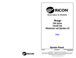
1
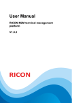
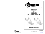
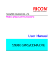
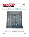
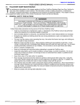
-PRINT- - TABLE OF CONTENTS- K-SERIES PUBLIC USE SERVICE MANUAL AUGUST 2013 MAINTENANCE III. MAINTENANCE AND REPAIR R egular maintenance of the Ricon K-Series® Public Use wheelchair lift will optimize its performance and reduce the need for repairs. This chapter contains lubrication and cleaning instructions, a maintenance schedule, troubleshooting section, and maintenance diagrams. CAUTION This Ricon product is highly specialized. Maintenance and repairs must be performed by an authorized Ricon service technician using Ricon replacement parts. A. LUBRICATION CAUTION Do not lubricate motor or other electrical components. Lubrication of electrical components may collect dirt and debris, causing short circuits. Lubrication should be performed at least every six months or sooner depending on usage. Refer to Figure 3-1 and the following Maintenance Schedule. Lubricate lift at points indicated with lubricants specified. 1 TORSION SPRINGS (BOTH SIDES) "A" DETAIL "A" "B" 1 KNUCKLE LINKS (BOTH SIDES) 2 1 TORSION SPRINGS (BOTH SIDES) 1 HINGE 2 DETAIL "B" 1 LUBRICATE WITH PENETRATING OIL 2 LUBRICATE WITH DRY LUBRICANT (GRAPHITE) FIGURE 3-1: LIFT LUBRICATION POINTS 32DSSK06.B.3 3-1 MAINTENANCE B. K-SERIES PUBLIC USE SERVICE MANUAL AUGUST 2013 CLEANING Regular cleaning with mild soap (i.e. hand soap, car wash liquid) and drying thoroughly will protect lift painted surfaces. Cleaning is especially important in areas where roads are salted in winter. Make sure that lift pivot points remain clear and clean prior to lubrication. C. MAINTENANCE SCHEDULE Under normal operating conditions, maintenance inspections are required at least every six months (1750 cycles) and a thorough inspection should be performed at service intervals referenced in Table 3-1. Service should be increased under conditions of heavy use (more than 10 cycles per day.) TABLE 3-1: MAINTENANCE SCHEDULE SERVICE POINT ACTION TO PERFORM 10 CYCLES Overall condition Listen for abnormal noises as lift operates (i.e. grinding or binding noises.) Control pendant Verify that control pendant is undamaged and cable connector is tight. 150 CYCLES Electrical wiring Inspect electrical wiring for frayed wires, loose connectors, etc. Vehicle interlock Place vehicle in non-interlock mode and verify that lift does not operate. Decals Verify that lift decals are properly affixed, clearly visible, and legible. Replace, if necessary. Handrails Verify that handrail fasteners are properly tightened. Lift mounting points Verify that vehicle mounting and support points are undamaged. Verify that mounting bolts are sufficiently tight and free of corrosion. Main lifting pivots Verify that link pins on arms are properly installed, free from damage, and locked in position. Platform pivot points Verify that platform moves freely, without binding, and does not wobble. Bridgeplate Verify that bridgeplate operates without binding during lift functions. Verify that bridgeplate deploys fully when platform stops at floor level. Verify bridgeplate rests flat against baseplate. Front rollstop Verify that rollstop is opened completely when platform is at ground level. Verify that rollstop closes and locks when platform leaves ground. Hydraulic power unit CAUTION Check and add fluid when platform is at ground level. Fluid that is added when platform is raised will overflow when platform is lowered. Verify that pump hydraulic fluid level is at FULL mark when platform is at ground level. Add Texaco 01554 Aircraft Hydraulic Oil or equivalent U.S. mil spec H5606G fluid. Verify there are no hydraulic fluid leaks. Verify that manual backup pump operates properly. 1800 CYCLES Cleaning and lubrication 1. Clean lift with mild soap and water and wipe dry. Prevent rust by coating all surfaces with a light weight oil. Remove excess oil. 2. Spray penetrating oil (Curtisol Red Grease 88167 or WD-40) where specified following directions on container. Remove excess grease from surrounding areas. CAUTION A Ricon authorized dealer must perform the following safety check. 3600 CYCLES 3-2 32DSSK06.B.3 K-SERIES PUBLIC USE SERVICE MANUAL AUGUST 2013 MAINTENANCE TABLE 3-1: MAINTENANCE SCHEDULE SERVICE POINT ACTION TO PERFORM Hydraulic cylinder, hoses and fittings Check hydraulic cylinder for evidence of leaks. Inspect hydraulic hoses for damage. Verify that all fittings are tight. END OF TABLE D. TROUBLESHOOTING The troubleshooting guides are designed to provide logical starting points to locate general problems that could occur with lift. However, not all possible problems or combinations of problems are listed. For troubleshooting lift, refer to Table 3-2. The guide does not incorporate routine safety precautions or preliminary procedures, and assumes that vehicle battery is fully charged and battery terminals/connectors are clean and tight. WARNING THE TROUBLESHOOTING GUIDES DO NOT INCORPORATE ROUTINE SAFETY PRECAUTIONS OR PRELIMINARY PROCEDURES. DURING THE RICON WARRANTY PERIOD ONLY A TRAINED, AUTHORIZED RICON SERVICE TECHNICIAN CAN PERFORM TROUBLESHOOTING. AFTER THE WARRANTY PERIOD, IT IS RECOMMENDED THAT TROUBLESHOOTING CONTINUE TO BE PERFORMED BY AN AUTHORIZED RICON SERVICE TECHNICIAN. 1. LIFT TROUBLESHOOTING TABLE 3-2: LIFT OPERATIONAL TROUBLESHOOTING GUIDE SYMPTOM Hydraulic fluid leaks Rollstop does not open Lift functions Abnormal operation. No operation. 32DSSK06.B.3 POSSIBLE CAUSE REMEDY Loose hydraulic fitting. Make sure fitting is PROPERLY tightened. Hydraulic component defective. Do not use lift until repairs are made by an authorized Ricon service technician. Obstruction of rollstop release latch. Raise lift and remove obstruction. Obstruction in lifting frame. Remove obstruction and check for any damage Backup pump manual release valve OPEN. Turn manual release valve CLOCKWISE until slightly snug. Hydraulic fluid may be low. While platform is at GROUND LEVEL, be certain that pump hydraulic fluid level is maintained at required FULL level. Add only Texaco 01554 Aircraft Hydraulic Oil or equivalent U.S. mil spec H5606G fluid. Air may be trapped in hydraulic system. Purge hydraulic system by operating lift through its maximum range of travel for at least four complete cycles. (For vehicles that do not use full travel of lift, the maximum range of travel is accomplished by raising vehicle on a service hoist or ramp.) Control system circuit breaker tripped. Reset circuit breaker. Backup pump manual release valve OPEN. Turn manual release valve CLOCKWISE until slightly snug. Hydraulic hose or fitting leak. Contact an authorized Ricon service technician for repair. 3-3 MAINTENANCE K-SERIES PUBLIC USE SERVICE MANUAL AUGUST 2013 Hydraulic fluid may be low. While platform is at GROUND LEVEL, be certain that pump hydraulic fluid level is maintained at required FULL level. Add only Texaco 01554 Aircraft Hydraulic Oil or equivalent U.S. mil spec H5606G fluid. Air may be trapped in hydraulic system. Purge hydraulic system by operating lift through its maximum range of travel for at least four complete cycles. (For some vehicles, the maximum range of travel is accomplished by raising vehicle on a service hoist or ramp.) END OF TABLE 2. PUMP SOLENOID LED STATUS INDICATOR Refer to Figure 3-2. Two solenoids provide a margin of safety if one of the solenoids fails with its contacts closed. A status two-color indicator LED is located between the two 8A circuit breakers to monitor the condition of the two solenoids. The LED is normally off when the pump is not operating and becomes green when the pump operates. When the pump is not operating and the top solenoid has failed the LED will be red. The LED will be green when the side solenoid has failed. LED STATUS INDICATOR TOP PUMP SOLENOID SIDE PUMP SOLENOID FIGURE 3-2: STATUS INDICATOR FOR PUMP SOLENOIDS 3. BRIDGEPLATE CABLE ASSEMBLY REPLACEMENT The following steps provide instructions for replacing the bridgeplate (also known as inner rollstop or IRS) cable assembly. Refer to Figure 3-3 on following page. Please follow these instructions carefully. Contact Ricon Product Support if you need assistance. 1) Study the routing of the cable before removing it. 2) Deploy the lift platform to vehicle floor level. Be certain that bridgeplate is resting against baseplate assembly. 3) Remove pinch point shields from the left and right vertical arm assemblies. 4) Assemble and secure one end of an IRS cable to the IRS pulley mount block (#1; located inside the left vertical arm assembly) using a hex screw, bushing, and washer. 3-4 32DSSK06.B.3 AUGUST 2013 K-SERIES PUBLIC USE SERVICE MANUAL MAINTENANCE 5) Route the cable around the IRS pulley mount block bushing (#2). Verify that cable is routed between the bushing tab and the point where the cable makes contact with the bushing. Install washer and hex nut over bushing and cable assembly. 6) Continue to route the cable around grooved bearings #3, #4, and #5. 7) Route the cable down the length of the vertical arm assembly and around grooved bearing #6. 8) Assemble and secure the end of the IRS cable to the left side of the bridgeplate (#7) using a hex screw, washer, bushing, and he nut. Be sure to install a hex nut on the inside of the inner rollstop. 9) Repeat for right side. 10) Reinstall pinch point shields removed in step 2. 32DSSK06.B.3 3-5 MAINTENANCE K-SERIES PUBLIC USE SERVICE MANUAL AUGUST 2013 FIGURE 3-3: BRIDGEPLATE CABLE ROUTING 4. LIMIT SWITCH STATES Refer to Figure 3-4. The limit switch actuation chart shows the state of all limit switches as the platform travels from stowed, to vehicle floor level, and then to ground level. The solid line segments (▬) represent current flow through the normally CLOSED switch contacts, and the open line segments (═) represent current flow through the normally OPEN switch contacts. The heavy dashed lines (∎ ∎ ∎ ) show switch states when platform is beyond normal travel boundaries. This is useful in showing the operation of switches that change states at stowed or ground level positions. For proper operation of lift, the switch actuations must overlap as shown. 3-6 FIGURE 3-4: LIMIT SWITCH ACTUATION CHART 32DSSK06.B.3 AUGUST 2013 E. K-SERIES PUBLIC USE SERVICE MANUAL MAINTENANCE HYDRAULIC CIRCUIT DIAGRAM FIGURE 3-5: K-SERIES HYDRAULIC CIRCUIT DIAGRAM 32DSSK06.B.3 3-7 MAINTENANCE F. K-SERIES PUBLIC USE SERVICE MANUAL AUGUST 2013 ELECTRICAL WIRING DIAGRAM 1. DIAGRAM LEGENDS a. Wire Color Codes TABLE 3-3: WIRE COLOR CODES LETTER COLOR LETTER COLOR BK Black R Red BL Blue VI Violet BR Brown GY Gray GN Green W White O Orange Y Yellow END OF TABLE b. Electrical Connector Description Refer to Figure 3-6. The standard electrical connectors, used by Ricon are Molex .062” Series. These connectors have terminal numbers molded onto the back; use these numbers and wire colors to identify wires. FIGURE 3-6: MOLEX CONNECTORS c. Diagram Labels FIGURE 3-7: DIAGRAM LABELS 3-8 32DSSK06.B.3 K-SERIES PUBLIC USE SERVICE MANUAL AUGUST 2013 d. MAINTENANCE Electrical Symbols Figure 3-8 defines the symbols used on the electrical wiring diagram. FIGURE 3-8: ELECTRICAL WIRING DIAGRAM SYMBOLS 32DSSK06.B.3 3-9 MAINTENANCE K-SERIES PUBLIC USE SERVICE MANUAL AUGUST 2013 2. WIRING DIAGRAM Refer to Figures 3-9 and 3-10 on the following two pages. The diagram is divided into two sheets. 3 - 10 32DSSK06.B.3 K-SERIES PUBLIC USE SERVICE MANUAL AUGUST 2013 RED (TOP) MOTOR CONTACTOR (SIDE) MAINTENANCE MOTOR CONTACTOR (TOP) DOWN VALVE SLO-BLOC VALVE GRN (SIDE) PLATFORM PRESSURE SWITCH N/C R R 1 FAST GN 2 PUMP ON P15 J15 P16 J16 W 3 DOWN VALVE GN BK 4 12V-8A R 1 P3 J3 GN 2 W/O 3 SLOW BLOCK DIODES BL BK 4 V O W/BK BK J14 P14 J13 P13 UP enable W STOW enable NC STOW-LOCK SOLENOID #4 R NO LIFT CONTROL CAM STOW STATUS CUTOFF SWITCHES (2EA) GN DOWN enable BK DEPLOY enable 24 VDC W BK 2 3 4 5 6 1 2 NO 3 4 5 R BK 1 INTERLOCK O BK NC GN COM DEPLOY DOWN W UP O STOW R 12V-8A 50A 6 7 J22 J23 PENDANT VEHICLE INTERFACE 8 9 FIGURE 3-9: K-SERIES DOT PUBLIC USE LIFT SCHEMATIC – SHEET 1 32DSSK06.B.3 3 - 11 MAINTENANCE K-SERIES PUBLIC USE SERVICE MANUAL BL AUGUST 2013 BR 8A HANDRAIL LIGHTS 8A 1 J21 P21 BK R 2 P20 J20 R BK CYCLE COUNTER FLASHING LIGHT RED O W BK BL GN TX R RX BRIDGEPLATE SWITCH YEL 1 2 3 4 5 6 P19 RX TX 1 2 W/O V BK R BK W BL 1 2 3 4 1 2 3 J17 P10 P13 J10 J13 1 2 1 2 J6 5 O 6 BK 4 BK BR 3 BK 2 R J19 1 1 2 1 2 J8 J17 SET 2 V 2 BL 3 (DO NOT SERVICE) BK 7 P18 N/C 8 1 2 1 Y 9 J18 3 T2 T1 T3 T4 2 BL BR O W/O J11 P11 W/O 6 SET 1 PRINTED CIRCUIT BOARD O 4 BR 5 J9 BL J7 W 1 J12 GN 10 P12 RED BLU All wire is 18 gauge unless noted otherwise. -BACK TO TOP- 3 - 12 SAFETY BELT SWITCH HANDRAIL LIGHTS FIGURE 3-10: K-SERIES DOT PUBLIC USE LIFT SCHEMATIC – SHEET 2 - NEXT CHAPTER32DSSK06.B.3