1
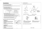
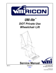
Innovation in Mobility UNI-lite TM Personal Use Wheelchair Lift PRINT Operator Manual 09/24/01 32DULP01.A U. S. Patent No. 5,234,311 Printed in the United States of America 92-2001 RICON CORPORATION All Rights Reserved This RICON product must be installed and serviced by authorized RICON service technicians. The operator must refer to this manual for operating instructions, and retain it for future reference. Customer Name: Installing Dealer: Date Installed: Serial Number: 32DULP01.A i REVISION RECORD REV PAGES 32DULP01. A All DESCRIPTION OF CHANGE New release, in two-book format. END OF LIST ii 32DULP01.A ECR/ECO 3796/4809 TABLE OF CONTENTS Chapter: Page I. INTRODUCTION..........................................................................................................1-1 A. RICON FIVE-YEAR LIMITED WARRANTY.......................................................... 1-1 B. SHIPMENT INFORMATION................................................................................. 1-3 C. GENERAL SAFETY PRECAUTIONS.................................................................... 1-3 D. MAJOR LIFT COMPONENTS .............................................................................. 1-4 II. OPERATING INSTRUCTIONS ....................................................................................2-1 A. SAFETY PRECAUTIONS...................................................................................... 2-1 B. DAILY SAFETY CHECK ....................................................................................... 2-2 C. LIFT FUNCTIONS................................................................................................. 2-3 D. CONTROLS AND INDICATORS .......................................................................... 2-3 E. LIFT OPERATION................................................................................................. 2-7 III. MAINTENANCE...........................................................................................................3-1 A. MAINTENANCE INFORMATION.......................................................................... 3-1 B. CLEANING AND LUBRICATION.......................................................................... 3-1 C. ELECTRICAL SYSTEM ........................................................................................ 3-1 D. MAINTENANCE SCHEDULE ............................................................................... 3-1 E. LIFT DECALS....................................................................................................... 3-2 32DULP01.A iii I. INTRODUCTION T he RICON UNI-lite Personal Use Wheelchair Lift provides wheelchair access to personal vans. With its lightweight aluminum alloy construction it has little effect on vehicle handling. The lift is designed to be operated by a person in a wheelchair, or by an attendant. The unique, adjustable post design means that UNI-lite fits standard and raised doors of most full-size vans and some minivans. The large non-skid platform accommodates most wheelchairs, yet the lift intrudes very little on interior space. UNI-lite lifts up to 600 pounds (273 kilograms). Standard features of the UNI-lite are twin handrails, a powerful electric motor and direct gear drive, and a powered roll stop. The UNI-lite also contains a built-in manual backup system. This manual contains operation and maintenance instructions for the UNI-lite. It is important that operators be completely familiar with the Operating Instructions chapter of this manual. For installation instructions and spare parts , please refer to the service manual. Once the UNI-lite is installed, it is important that the lift be properly maintained by following the recommended cleaning, lubrication, and inspection procedures. If there are questions about this manual or additional copies are needed, please contact Ricon Product Support at one of the following locations: Ricon Corporation 7900 Nelson Road Panorama City, CA 91402..............................................................(818) 267-3000 Outside (818) Area Code................................................................(800) 322-2884 World Wide Website ................................................................ www.riconcorp.com Ricon U.K. Ltd. Littlemoss Business Park, Littlemoss Road Droylsden, Manchester United Kingdom, M43 7EF.....................................................(+44) 161 301 6000 A. RICON FIVE-YEAR LIMITED WARRANTY (refer to following page) 32DULP01.A 1-1 RICON CORPORATION FIVE-YEAR LIMITED WARRANTY Ricon Corporation (Ricon) warrants to original purchaser of this product that Ricon will repair or replace, at its option, any part that fails due to defective material or workmanship as follows: • Repair or replace parts for a period of one year from date of purchase. • Labor costs for specified parts replace under this warranty for a period of one year from date of purchase. A Ricon rate schedule determines the parts covered and labor allowed. • Repair or replace lift power train parts for a period of five years from date of purchase. A list of parts covered can be obtained from your authorized Ricon dealer. If You Need to Return a Product: Return this Ricon product to your installing dealer. Please give as much advance notice as possible and allow a reasonable amount of time for repairs. If You are Traveling: All authorized Ricon dealers honor this warranty. Consult telephone directory or call our Product Support department for the name of nearest authorized Ricon dealer. This Warranty does not Cover: • Malfunction or damage to product parts caused by accident, misuse, lack of proper maintenance, neglect, improper adjustment, modification, alteration, the mechanical condition of vehicle, road hazards, overloading, failure to follow operating instructions, or acts of Nature (i.e., weather, lightning, flood). Note: Ricon recommends that this product be inspected by an authorized Ricon service technician at least once every six months, or sooner if necessary. Any required maintenance should be performed at that time. WARNING! THIS PRODUCT HAS BEEN DESIGNED AND MANUFACTURED TO EXACT SPECIFICATIONS. MODIFICATION OF THIS PRODUCT IN ANY RESPECT CAN BE DANGEROUS. This Warranty is Void if: • The product has been installed or maintained by someone other than an authorized Ricon service technician. • The product has been modified or altered in any respect from its original design without written authorization by Ricon. Ricon disclaims liability for any personal injury or property damage that results from operation of a Ricon product that has been modified from the original Ricon design. No person or company is authorized to change the design of this Ricon product without written authorization by Ricon. Ricon's obligation under this warranty is exclusively limited to the repair or exchange of parts that fail within the applicable warranty period. Ricon assumes no responsibility for expenses or damages, including incidental or consequential damages. Some states do not allow the exclusion or limitation of incidental or consequential damages, so the above limitation or exclusion may not apply. Important: The warranty registration card must be completed and returned to Ricon within 20 days after installation of this Ricon product for the warranty to be valid. The warranty is not transferable. The warranty gives specific legal rights, and there may be other rights that vary from state to state. 1-2 32DULP01.A B. SHIPMENT INFORMATION Ricon does not sell directly to the user because of the specialized nature of the product. Instead, the product is distributed through the worldwide network of authorized Ricon dealers, who perform the actual installation. ¡ When the product is received, unpack the product and check for freight damage. Claims for any damage should be made to the fright carrier immediately. ¡ Be sure the installation kit contains all items listed on the kit packing list. Please report any missing items immediately to the Ricon Product Support Department. The warranty and owner's registration cards must be completed and returned to Ricon within 20 days for the warranty to be valid. NOTE: The Sales/Service Personnel must review the Warranty and this Operator Manual with the user to be certain they understand safe operation of the product. Instruct the user to follow the operating instructions without exception. C. GENERAL SAFETY PRECAUTIONS ¡ An injury, no matter how slight, should always be attended. Always administer first aid or seek medical attention immediately. To avoid injury, always exercise caution when operating and be certain that hands, feet, legs, and clothing are not in path of product movement. Read and thoroughly understand operating instructions before attempting to operate. Inspect product before each use. If an unsafe condition, unusual noises, or movements are present, do not use it until problem is corrected. Stand clear of doors and platform and keep others clear during operation. The product requires regular periodic maintenance. A thorough inspection is recommended at least once every six months. The product should be maintained at the highest level of performance. The following general safety precautions must be followed during operation: ¡ ¡ ¡ ¡ ¡ 32DULP01.A 1-3 D. MAJOR LIFT COMPONENTS The references used throughout this manual are illustrated in Figure 1-1 and defined in Table 1-1. Refer to Service Manual, Chapter IV “Parts Diagrams and lists” for more details. FIGURE 1-1: UNI-LITE PERSONAL USE WHEELCHAIR LIFT 1-4 32DULP01.A TABLE 1-1: UNI-LITE PERSONAL USE LIFT TERMINOLOGY REF NAME DESCRIPTION 1 Front Reference point from outside the vehicle looking inward. 2 Back 3 Left 4 Right 5 Serial number location Location of serial number decal. 6 Parallel Arms Left and right arms that connect the Main Posts to the Platform Posts. (These arms pivot as platform lowers to ground.) 7 Platform Support Chains Covered left and right chains that provide additional support for the platform. 8 Platform Roll Stop Barrier to prevent the wheelchair from slow, inadvertent rolling off the platform during lift operation. 9 Platform Platform where the wheelchair is positioned during lift operations. 10 Platform Posts Left and right posts connected to platform. (These posts enter and exit vehicle as the platform is raised and lowered.) 11 Bridgeplate Plate that extends across the vehicle threshold and the platform. 12 Base Plate Lift support plate bolted to vehicle floor. 13 Electrical Box Assembly Assembly that contains the lift controller and electrical circuit breakers. 14 Control Pendant Hand-held or lift-mounted pendant that contains switches used to control the lift operating functions. 15 Main Posts Left and right posts that stay inside the vehicle. (These posts are not directly connected to the platform.) 16 Motor and Gear Box 12 volt direct current (DC) motor and gear box that power the lift functions. 17 Drive Shaft Chain drive shaft for lift operations. 18 Handrail Switch The switch that operates the UP/DOWN function of the lift. 19 Speed Wrench Wrench that is used to manually operate the lift. END OF TABLE 32DULP01.A 1-5 II. OPERATING INSTRUCTIONS T his chapter contains safety precautions, daily safety check instructions, control and indicator descriptions, and operating instructions for the RICON UNI-lite Personal Wheelchair Lift. This chapter must be read and thoroughly understood attempting to use the UNI-lite. A. SAFETY PRECAUTIONS The safety precautions must be complied with at all times when operating the UNI-lite: ¡ Refer to Figure 2 -1. A hazardous situation may exist when using the lift if the vehicle is parked on any type of slope. Always operate the lift with the vehicle on level ground. FIGURE 2-1: SLOPED PARKING HAZARD ¡ ¡ ¡ ¡ ¡ ¡ Vehicle must be safely parked with parking brake ON before using lift. Inspect lift before use. DO NOT use lift if an unsafe condition exists, or unusual noises or movements are noticed, and contact a Ricon authorized dealer for lift repair. Read and comply with all warning labels and symbols affixed to wheelchair lift. Refer to Figure 2-2. Wheelchair occupant should FACE OUTWARD when entering or exiting vehicle. DO NOT back onto platform when exiting vehicle. FACE OUTWARD, if possible, and make sure that platform is at the same level as floor. Check that outer rollstop is up and locked. Do not place equipment or furniture inside vehicle that may prevent pivoting of your wheelchair. Being able to pivot assures that you can safely exit facing outward. 32DULP01.A FIGURE 2-2: SAFETY DECAL 2 -1 ¡ ¡ ¡ ¡ ¡ ¡ ¡ ¡ ¡ ¡ ¡ ¡ ¡ ¡ The outer rollstop is intended to prevent slow, or unintentional, rolling off the platform. The outer rollstop is not designed to stop a quick moving wheelchair. The wheelchair might tip and possibly injure its occupant if the small front wheels collide hard with the rollstop. The large rear wheels of a quick moving wheelchair can also roll over the rollstop. Use great care, board platform slowly, and lock wheelchair brakes. Be certain wheelchair fits safely on platform; it must not extend beyond edges or interfere with operation of rollstop. Do not operate with a load in excess of 600 lbs (273 kg). Keep arms, legs, and clothing away from moving lift parts. The lift is for ONE wheelchair and its occupant. Do not overload lift. Refer to Figure 2-3. Keep others clear while operating lift. Do not allow an untrained person to operate lift. Careful supervision is necessary if used by or near children. Do not allow anyone to stand on bridgeplate. A bent bridgeplate can interfere with the platform as it raises and lowers. Lock wheelchair brakes before moving platform (power chair users should turn off power and set brake). FIGURE 2-3: STAND CLEAR Use great care in wet conditions, because the OF LIFT wheelchair brakes are less effective if wheels or platform are wet. Never leave platform outside of vehicle. Return to stowed position after use. Do not place a wheelchair on platform if it is too large for the vehicle. The wheelchair must be able to pivot freely inside vehicle to comply with lift instructions for entering and exiting vehicle. Do not rely on an audible threshold warning device to provide assurance that it is safe to exit the vehicle facing backwards. This device may be inoperative or unheard, and you might exit backwards when the platform is on the ground! Exit facing outward, and be certain the platform is at floor level. Read and understand these safety precautions. Review them periodically and ask any attendants or other operators to read them as well. Contact a Ricon authorized dealer or Ricon Product Support if there are questions. B. DAILY SAFETY CHECK Inspect lift before each use and check that following conditions are met before operating: ¡ All functions operate properly. DO NOT use if unusual noises or movements are present, and contact an authorized Ricon dealer for repair. ¡ Vehicle interlock is operating properly. ¡ No objects that may interfere with operation are present. ¡ General appearance and lubrication are satisfactory, and all fasteners are tight 2 -2 32DULP01.A C. LIFT FUNCTIONS TABLE 2-1: LIFT FUNCTIONS FUNCTION DESCRIPTION → / DEPLOY Platform unfolds/deploys out of vehicle from the stowed position. (If equipped with a Ricon power door operator, the doors automatically open before the lift deploys.) ↓ / DOWN Platform is lowered from vehicle floor level to ground level (rollstop automatically lowers when platform reaches ground level.) ↑ / UP Platform is raised from ground level to vehicle floor level (rollstop automatically rises when platform leaves ground level). ← / STOW Platform folds/stows from vehicle floor level to the stowed position. (If equipped with a Ricon power door operator, the doors automatically close after the lift stows.) END OF TABLE D. CONTROLS AND INDICATORS 1. CONTROL PENDANT Refer to Figure 2-3. The lift is controlled with a hand held, hard-wired remote control pendant. It has two dual-position rocker switches. The lift functions are performed by pushing and holding one end of an appropriate switch. Pushing DEPLOY switch unfolds lift from vehicle and pushing STOW switch folds platform into vehicle. Pushing DOWN switch lowers lift towards ground and pushing UP switch raises lift towards floor. The pendant is stowed on a wall-clip inside vehicle. FIGURE 2-3: CONTROL PENDANT 32DULP01.A 2 -3 2. HANDRAIL SWITCH Refer to Figure 2-4. The handrail switch is a supplemental spring-loaded switch that may be used by the platform occupant to control the UP and DOWN functions of the lift. The switch is on the left handrail (or optional right handrail) of the platform. To operate the desired function, push and hold the switch in the appropriate direction until the function is completed. FIGURE 2-4: HANDRAIL SWITCH 3. SPEED WRENCH Refer to Figure 2-5. The speed wrench is used to turn the lift motor in the event of lift electrical failure. The wrench fitting is attached to the motor-shaft and turned by hand counter-clockwise to DEPLOY the lift, or clockwise to STOW the lift. FIGURE 2-5: SPEED WRENCH 2 -4 32DULP01.A 4. ELECTRICAL CONTROLS AND INDICATORS Refer to Figure 2-6. The lift electrical controls are inside the electrical box assembly. FIGURE 2-6: ELECTRICAL BOX ASSEMBLY a. Controller Indicators The controller indicator lights are located on the solid-state controller (behind the electrical box assembly cover). Refer to Chapter IV of this manual for indicator descriptions. CAUTION! Do not replace a circuit breaker with one of greater amperage. Locate and repair short circuit to correct problem. b. Control System Circuit Breaker The control system circuit breaker is rated at 5 amps and is designed to interrupt electrical power to the control system in the event of a short circuit. If a short circuit occurs, the circuit breaker button will “pop-up”. Wait 10-15 seconds before attempting to reset. If pressing and releasing the button does not restore power, DO NOT press and hold. Contact an authorized Ricon service technician for repair. 32DULP01.A 2 -5 c. Circuit Breaker for Optional Door Operator The circuit breaker for the optional door operator is rated at 30 amps and is designed to interrupt electrical power to the door operator in the event of a short circuit. If a short circuit occurs, the circuit breaker button will “pop-up”. Wait 10-15 seconds before attempting a reset. If pressing and releasing the button does not restore power, DO NOT press and hold. Contact an authorized Ricon service technician for repair. d. Main Circuit Breaker Refer to Figure 2-7. The main circuit breaker is rated at 50 amps (located in the vehicle engine compartment) and is designed to interrupt electrical power to the lift electrical system in the event of a short circuit. If a short circuit occurs, the circuit breaker reset tab will “pop-down”. Wait at least 30 seconds before attempting a reset. If pressing the reset tab UP and releasing does not restore power, DO NOT press and hold. Contact an authorized Ricon service technician for repair. FIGURE 2-7: MAIN CIRCUIT BREAKER 2 -6 32DULP01.A E. LIFT OPERATION WARNING! IMPROPER USE OF LIFT CAN RESULT IN PERSONAL INJURY. USERS MUST READ AND FOLLOW OPERATING INSTRUCTIONS IN THIS OPERATOR MANUAL. COPIES OF THE OPERATOR MANUAL ARE AVAILABLE FROM: RICON CORPORATION 7900 NELSON ROAD PANORAMA CITY, CA 91402 (818) 267-3000 OR (800) 322-2884 § DO NOT EXCEED RATED LOAD CAPACITY OF 600 POUNDS (273 KG). § PRIOR TO USE, INSPECT WHEELCHAIR LIFT FOR PROPER FUNCTION, REQUIRED MAINTENANCE, OR DAMAGE. IF A PROBLEM EXISTS, DO NOT USE LIFT AND CONTACT AN AUTHORIZED RICON DEALER FOR REPAIR. § THIS LIFT IS DESIGNED FOR USE BY WHEELCHAIR OCCUPANTS, ONLY. DO NOT USE FOR STANDING PASSENGERS. RICON CORPORATION DISCLAIMS LIABILITY FOR DAMAGE OR PERSONAL INJURY RESULTING FROM MODIFICATION TO THE LIFT, LACK OF MAINTENANCE, REPAIR, NEGLIGENCE, ABUSE, OR FAILURE TO FOLLOW LIFT OPERATING INSTRUCTIONS. ¡ ¡ ¡ ¡ ¡ Before operating lift, be certain vehicle is safely parked on a level area away from traffic. Provide space for lift operation and passenger boarding. The lift operator must take special care to be certain that area is clear before deploying lift. Be certain there are no obstacles beneath platform. Open doors completely if vehicle is not equipped with a power door operator. If equipped with a power door operator, the vehicle doors will automatically open before platform deploys or close after platform is stowed. If so equipped, be certain that safety interlock mechanism (e.g. transmission, parking brake, etc.) is properly engaged before attempting to operate lift. The lift will not operate until this feature has been engaged properly. The vehicle should be driven for 10 minutes to replenish the energy drawn from the battery during one lift cycle. This is necessary regardless of the battery rating or the presence of a dual battery system. If the vehicle is driven less between lift cycles, it is recommended that a supplementary charger be used to avoid excessive battery drain or damage. WARNING! ATTENDANT SHOULD REMAIN NEAR PASSENGER TO RENDER IMMEDIATE ASSISTANCE, IF NECESSARY. KEEP OTHERS CLEAR WHEN OPERATING LIFT. MAINTAIN PRESSURE ON SWITCH UNTIL FUNCTION IS COMPLETE. BE CERTAIN WHEELCHAIR FITS PROPERLY ON PLATFORM AND DOES NOT CONTACT ROLLSTOP, WHICH COULD PREVENT IT FROM LOCKING WHEN PLATFORM RISES. 32DULP01.A 2 -7 1. TO ENTER VEHICLE: DEPLOY PLATFORM - Push and hold the stow → portion of the STOW/DEPLOY switch until the lift fully deploys and stops automatically at vehicle floor level. LOWER PLATFORM - Push and hold the down ↓ portion of the UP/DOWN switch until the platform reaches ground level and the outer rollstop opens completely. — Carefully place wheelchair centrally on platform, facing outward, and LOCK WHEELCHAIR BRAKES. Be certain wheelchair is properly positioned on platform and does not contact outer rollstop and prevent it from locking as the platform rises. RAISE PLATFORM - Push and hold the up ↑ portion of the UP/DOWN switch until the platform rises and stops automatically at floor level. 2. TO EXIT VEHICLE: DEPLOY PLATFORM - Push and hold the deploy → portion of the STOW/DEPLOY switch until the lift fully deploys and stops automatically at floor level. ALWAYS EXIT VEHICLE FACING OUTWARD. Be certain platform is at vehicle floor level. Verify that platform rollstop is in the up position, and is locked. Carefully place wheelchair in center of platform and LOCK WHEELCHAIR BRAKES. LOWER PLATFORM - Push and hold the up ↑ portion of the UP/DOWN switch until the platform reaches ground level and the outer rollstop opens completely. — Release wheelchair brakes and carefully exit platform. — 3. TO STOW PLATFORM: With the platform at vehicle floor level, push and hold the stow ← portion of the STOW/DEPLOY switch until the lift stops automatically in the closed (or folded) position. Be certain lift has folded completely before closing vehicle doors. On vehicles equipped with power doors, continue to push the stow ← portion of the STOW/DEPLOY switch until the doors close completely. 4. MANUAL OPERATION: In the event the lift becomes inoperable under its own power, it can be operated using the manual backup system as follows: — — — 2 -8 Verify that the vehicle is on a level area and away from any traffic. Allow enough space for lift operation and passenger boarding. If a break-down situation exists and the vehicle cannot be moved so that the lift system can be operated safely, the operator must summon emergency assistance to move the vehicle before operating the lift. Fully open vehicle doors. Verify that there are no obstacles in the path of the lift. Disconnect cable at circuit breaker. 32DULP01.A — Refer to Figure 2-8 and the following sections for manual operation instructions: FIGURE 2-8: MANUAL OPERATION DECAL WARNING! REMOVE SPEED WRENCH AFTER MANUAL OPERATION, AND BEFORE RECONNECTING POWER CABLE TO CIRCUIT BREAKER. DO NOT OPERATE LIFT WITH EMERGENCY WRENCH ATTACHED; IT MAY DISENGAGE AND BE THROWN, CAUSING POSSIBLE INJURY AND DAMAGE. MAKE SURE LIFT IS DISCONNECTED AT CIRCUIT BREAKER DURING A MANUAL OPERATION. a. Deploying/Lowering of Platform CAUTION! The lift passenger or attendant must follow the lift operation instructions described in this manual to enter or exit the vehicle. ÷ ÷ ÷ Attach speed wrench to the motor shaft and turn wrench in a continuous counter-clockwise direction until the platform reaches vehicle floor level. Continue to turn speed wrench counter clockwise until platform reaches ground level and the platform rollstop opens completely. Contact an authorized Ricon service technician for lift repair. 32DULP01.A 2 -9 b. Raising/Stowing of Platform: CAUTION! The lift passenger or attendant must follow the lift operation instructions described in this manual to enter or exit the vehicle. ÷ ÷ ÷ 2 - 10 Attach speed wrench to the motor shaft and, from ground level, raise platform by turning speed wrench in a continuous clockwise direction until the platform is safely positioned at the vehicle floor-level. Continue to turn speed wrench clockwise until the platform is completely folded inside the vehicle. Be certain lift has folded completely before closing vehicle doors. Contact an authorized Ricon service technician for lift repair. 32DULP01.A III. MAINTENANCE R egular maintenance of the RICON UNI-lite Personal Wheelchair Lift will provide optimum performance in addition to reducing the need for repairs. Ricon products are highly specialized and maintenance and/or repairs must be performed by an authorized Ricon service technician using Ricon replacement parts. During the Ricon warranty period maintenance inspections are required every six months, or sooner depending on usage. Additional maintenance information is available in the UNI-lite Personal Use Service manual, part number 32DULP02. This manual is available from Ricon in printed hard copy, or at the Ricon website in PDF format. The website is located at www.riconcorp.com. Click on RICON CORPORATION and then DEALER’S ROOM at the website. Entry to the dealer’s room will require a dealer number and a password. A. MAINTENANCE INFORMATION Additional maintenance information is available in the UNI-lite Personal Use Service manual, part number 32DULP02. This manual is available from Ricon in printed hard copy, or at the Ricon website in PDF format. The website is located at www.riconcorp.com. Click on RICON CORPORATION and then DEALER’S ROOM at the website. Entry to the dealer’s room will require a Dealer Number and a Password. B. ¡ CLEANING AND LUBRICATION Cleaning lift regularly is an important part of its maintenance, and will protect its su rfaces. All moving parts should be kept clean and lubricated. WARNING! SPRAYABLE SOLVENTS ARE EXTREMELY FLAMMABLE AND CONTAIN HARMFUL VAPORS. TO AVOID INJURY, FOLLOW SAFETY WARNING PRINTED ON LABEL. ¡ ¡ ¡ C. Chains should be clean but not lubricated. Chains should be cleaned with a sprayable penetrating solvent (such as WD-40®). Do not saturate chains or leave wet as this attracts dirt and dust. Chains should always be wiped dry after cleaning. The lift has been designed and manufactured for low maintenance. Cleaning and lubrication of all moving parts should be performed at least every six months, or sooner depending on usage. Do not lubricate motor or electrical components. ELECTRICAL SYSTEM No general maintenance is required on the electrical system. This system should, however, be inspected at least every six months for short circuits, frayed wires, loose connectors, etc. D. MAINTENANCE SCHEDULE TABLE 3-1: ROUTINE INSPECTION INSPECTION ACTION Pivot bearings Inspect for wear every six months Inspect platform barrier for damage and malfunction Repair/replace as needed Check all fasteners on lift for tightness Tighten as required 32DULP01.A 3 -1 Check hinge pins Replace as needed Check all mounting hardware Tighten/replace as needed Check electrical limit switch settings Adjust as needed Inspect chains and connection points Repair/replace as needed END OF TABLE E. LIFT DECALS FIGURE 3-1: DECAL LOCATIONS AND PART NUMBERS 3 -2 32DULP01.A