1
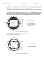
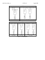
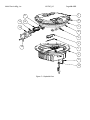
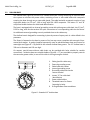
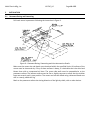
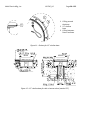
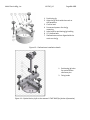
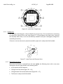
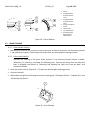
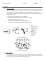
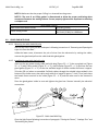
Multi Electric Mfg., Inc. IB LTHE_US Page 21 of 35 1. Positioning jig 2. Align the jig notch with the mark on the pavement 3. Circular level 4. Screws and spacers for the jig mounting 5. Lobe knob for positioning jig levelling 6. 12” shallow base 7. Shallow base notches aligned with the notch on the jig Figure 13 – Shallow base installation details 1. Positioning jig holes for optical device reference pins 2. Fixing knobs Figure 14 – Optical device (refer to the manual UT‐MT‐0485 for further information)