1
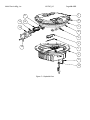
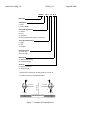
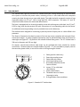
Multi Electric Mfg., Inc. IB LTHE_US Page 5 of 35 INDEX OF FIGURES Figure 1 – 12” Dome outside view .................................................................................................................................................. 7 Figure 2 – Lower Cover Outside View ............................................................................................................................................. 8 Figure 3 – Lower Cover Inside View ................................................................................................................................................ 8 Figure 4 – Wiring Diagram ............................................................................................................................................................. 9 Figure 5 – Exploded View ............................................................................................................................................................. 10 Figure 6 – Part List ....................................................................................................................................................................... 11 Figure 7 ‐ Complete P/N identification ......................................................................................................................................... 12 Figure 8 – Standard 12” shallow base ........................................................................................................................................... 13 Figure 9 – Pavement Boring, Sawcutting and Joint Intersection Details ........................................................................................ 16 Figure 10 – Example of Light Unit Configuration ........................................................................................................................... 17 Figure 11 – Gaskets for 12” shallow base ..................................................................................................................................... 20 Figure 12 – 12” shallow base for side or bottom ducts (method “B”) ............................................................................................ 20 Figure 13 – Shallow base installation details ................................................................................................................................ 21 Figure 14 – Optical device (refer to the manual UT‐MT‐0485 for further information) .................................................................. 21 Figure 15 – Gaskets for L‐868 base ............................................................................................................................................... 22 Figure 16 ‐ Lower Cover Fixing Screws .......................................................................................................................................... 25 Figure 17 ‐ Lower Cover with Pressure Valve ................................................................................................................................ 25 Figure 18 – Fixture Gaskets .......................................................................................................................................................... 26 Figure 19 ‐ Prism Cleaning ............................................................................................................................................................ 26 Figure 20 ‐ Prism Replacement .................................................................................................................................................... 27 Figure 21 – LED Module Replacement .......................................................................................................................................... 28 Figure 22 – Wiring diagrams for the heaters ................................................................................................................................. 29 Figure 23– Fixture Gaskets ........................................................................................................................................................... 30 Figure 24 – Prism Gasket ............................................................................................................................................................. 30 Figure 25 ‐ Cable Lead With Plug .................................................................................................................................................. 31 Figure 26 ‐ Lower Cover with Pressure Valve ................................................................................................................................ 32 Figure 27 ‐ Restoring the Monitoring Device ................................................................................................................................ 33