1
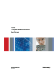
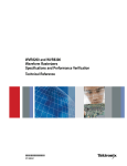
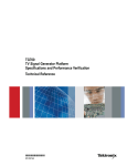
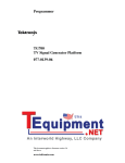
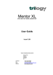
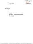
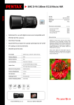
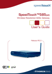
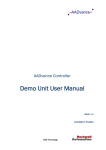
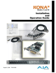
Multiformat Video Generator
TG700 Data Sheet
Features & Benefits
Multiformat Analog and Digital Test Signal Generation
Ideal Channel Configuration and Performance to Support Reference
Generator Needs
Modular Expandable Platform
Stay GenLock™ – Unique, Robust Genlock Mode provides Stable
Synchronization Signals for Digital and Traditional Broadcast Facilities
Applications
Sync Pulse Generator and Test Signal Generator for Post Production
and Broadcast Facilities
Test Signal Generator for Research and Development
Equipment Design and Maintenance
Data Sheet
AGL7 Analog Genlock Module.
GPS7 GPS Synchronization and Time Code Module.
The TG700 is a multiformat, analog and digital, precision signal generation
platform. Designed with the changing needs of the video industry in mind,
the TG700 offers sync pulse generation and test signal generation for a
wide array of analog, serial digital, and digital high-definition formats. The
TG700 Multiformat Video Generator has a modular architecture that offers
the flexibility to meet the single-format and growing multiformat needs of the
video professional. The TG700 mainframe allows up to four of the following
modules to be fitted in the mainframe.
The TG700 has a high stability reference. The AGL7 Analog Genlock
Module adds the capacity to lock to a variety of signals, which makes the
TG700 an ideal solution as the master house reference or slave reference
for broadcast and production/post-production applications. Three black
outputs are available and are selectable for HDTV tri-level or NTSC or PAL.
Additionally, the AGL7 can lock to a variety of formats to include NTSC/PAL
black and HDTV tri-level as well as 1, 3.58, 4.43, 5, and 10 MHz CW. When
the AGL7 is configured for Stay GenLock™ mode, a momentary loss of
synchronization at the genlock reference input will not cause a disturbance
in the TG700’s test signal and black outputs. When the genlock signal is
reapplied, the AGL7 will gradually reacquire lock, causing little disruption to
devices synchronized to the TG700 reference.
The GPS7 GPS Synchronization and Time Code Module includes an
integrated GPS receiver which can serve as the system timing reference.
Synchronization to the GPS timing signals ensures long-term stability,
and video frame alignment between independent systems. The GPS RF
coaxial signal input is available with 3.3 V or 5 V DC power output for the
GPS antenna enabling the user to select from a variety of GPS antennas
available on the market. The GPS7 also includes a genlock input with
VITC reader, enabling user-selectable configuration of the TG700 as
the master reference or as a slave to another master, depending on the
2
www.tektronix.com
ATG7 Composite Analog Test Generator.
dynamic requirements of each production. The GPS7 module will maintain
system timing by Stay GenLock™ technology even during periods of GPS
signal loss or genlock signal loss. Three black outputs are available and
are selectable for HDTV tri-level, NTSC, or PAL. Time code source can
be selectable to the time-of-day (with user-selectable offsets) from GPS
receiver, internal source, VITC on the reference input, LTC input, or to a
"program time" counter for elapsed-time time code. The Daylight Savings
Time (DST) adjustment could be recurring scheduled, based on calendar
rules. Time code is available as VITC on black outputs (GPS7, BG7), as
Ancillary Time Code (ATC) (HDVG7, HD3G7, SDI7), from four independent
LTC outputs (GPS7), and as a response to time requests on a Simple
Network Time Protocol (SNTP version 3.0) Server.
The ATG7 Composite Analog Test Generator supports PAL, NTSC, and
NTSC No Setup. It provides one test signal output, one color bar test
signal output, and two black outputs. The black outputs can independently
generate H, V, black burst, and subcarrier.
Multiformat Video Generator — TG700
AVG7 Analog Video Generator.
AG7 Audio Generator.
AWVG7 Analog Wideband Video Generator.
The AVG7 is an Analog Video Generator for 525/625 interlace formats
supporting component (Y'P'bP'r, G,B,R, Y/C), 525 Beta, and composite
(PAL, NTSC, NTSC No Setup). It provides two identical component outputs,
two identical Y/C and composite, or six identical composite outputs.
The AWVG7 is an Analog Wideband Video Generator that supports a
variety of HD analog component formats (Y'P'bP'r or GBR). The module
provides two identical component outputs with a bandwidth of 30 MHz.
Up to two AWVG7 Analog Wideband Video Generators can be placed in
a single TG700 mainframe.
BG7 Analog Black Generator.
The AG7 provides eight channels (4 AES/EBU pairs) of audio signal
generation. It also provides two channels (1 AES/EBU pair) of silence as
well as a 48 kHz word clock output.
The BG7 is an analog black generator with four independently selectable
outputs. The BG7 Black Generator supports NTSC and PAL black burst as
well as HDTV tri-level sync. With Option CB, two of the outputs can also
generate various analog NTSC and PAL color bar test signals.
www.tektronix.com
3
Data Sheet
DVG7 SD-SDI Digital Generator (shown with Option BK).
HDVG7 HD-SDI Digital Generator (shown with Option BK).
The DVG7 is a multiformat SD-SDI test signal generator. The DVG7
Digital Video Generator supports 525 line and 625 line serial digital
video at 270 Mb/s and NTSC composite digital at 143.181818 Mb/s. The
DVG7 Digital Video Generator has two identical test signal outputs. With
Option BK, two additional identical serial digital black signal outputs are
available.
The HDVG7 is a high-accuracy, multiformat, high-definition test signal
module that provides up to two identical 1.485 Gb/s serial digital video test
signal outputs in a broad variety of formats. With Option BK, two additional
identical serial black signal outputs are available. Ancillary Time Code
(ATC) generation is available when the GPS7 is installed in the TG700
mainframe. Up to two HDVG7 modules can be placed in a single TG700
mainframe.
The digital modules DVG7 and HDVG7 support AV timing mode and up to
16 channels of 20- or 24-bit audio sampled at 48 kHz embedded on the
test signal outputs. The user can independently set frequency and level
for each channel.
Full frame test and custom patterns can be generated for the AVG7,
AWVG7, DVG7, and HDVG7 modules. Simple full frame patterns are
available on V3.1 (or higher than V3.1) CD-ROM.
The HDLG7 is a test signal generator that provides two identical dual-link
high-definition serial digital interface (HD SDI) outputs. The module
4
www.tektronix.com
HDLG7 Dual Link HD-SDI Generator.
HD3G7 HD/3G-SDI Test Signal Generator
supports video formats that require the use of a dual-link interface, such as
4:4:4 R'G'B' at rates up to 1080i/60 Hz or 1080p/30 Hz, or 4:2:2: Y'C'bC'r
at rates up to 1080p/60 Hz. The HDLG7 supports several standard test
signals, and also has the unique ability to up-convert an arbitrary single-link
HD-SDI input signal to a dual-link format for the outputs. The HDLG7 also
supports digital cinema 2K formats and test patterns.
The HD3G7 is a test signal generator that provides two outputs of a
HD/3G-SDI video test signal. 720-line formats and 1080-line formats
described in SMPTE standards are supported for both Level A and Level B
mapping structures, including 4:4:4 and/or 12-bit sampling, Y'C'bC'r, R'G'B',
or XYZ color space, and 2K digital cinema formats. The 2×SMPTE 292M
HD-SDI format used by some 3D TV applications is also supported.
The HD3G7 can generate up to 32 channels of 24-bit 48 kHz embedded
audio, with independently set frequency and amplitude for each channel.
The HD3G7 also has the ability to generate other types of ancillary data,
such as video payload identifier, ancillary time code, and user-defined
packets.
The HD3G7 includes a wide variety of standard test signals, including
SMPTE color bars, pathological test patterns, and a programmable
moving zone plate pattern, and it also has the ability to up-convert an
input 1.485 Gb/s HD-SDI signal to a 3G output. The HD3G7 has a
clock/frame trigger output that can be used to synchronize the output with
an oscilloscope, for example.
Multiformat Video Generator — TG700
CW Input
SDI7 SD/HD/3G-SDI Test Signal Generator.
The SDI7 is a test signal generator that provides two independent channels
of SD/HD/3G-SDI video test signal generation in a variety of formats with
2 outputs for test and test/black signal generation per channel (3G-SDI
signal generation is optionally available). The SDI7 can generate up to
32 channels of 24-bit 48 kHz embedded audio, with independently set
frequency and amplitude for each channel. The SDI7 also has the ability
to generate other types of ancillary data, such as video payload identifier,
ancillary time code, and user-defined packets. The SDI7 includes a wide
variety of standard test signals, including SMPTE color bars, pathological
test patterns, and a programmable moving zone plate pattern, and it also
has the ability to generate full frame test signals created by the user. AV
timing signal generation, when used in conjunction with a waveform monitor,
can be used to ensure that audio and video are synchronized through a
video path. Circle, multi-language text, and color logo overlays may be
applied to the generated test signals to check aspect ratio, identify streams,
or apply station logos. The SDI7 has a clock/frame trigger output that can be
used to trigger an oscilloscope to be synchronous with the video output.
Characteristics
AGL7, Analog Genlock Module
Description
Input Connector
Input Impedance
Input Signal
Amplitude
Frequency
Return Loss
CW Lock Stability
Over the amplitude
range
Jitter
BNC ×1, internally terminated
75 Ω
CW (continuous wave)
2 V (1 to 2.25) Vp-p
NTSC/PAL FSC, 1/5/10 MHz
>30 dB to 30 MHz
<1 ns
<1 ns (typ. 1°) with CW input S/N >50 dB
Genlock
Characteristic
Description
Genlock Time Adjustment
Range
Anywhere in the color frame
Resolution
<0.5° of NTSC/PAL subcarrier
1 ns with tri-level sync input
Color Framing
Keeps accuracy even with ±45° SCH error of input
reference input
Reference Outputs
Characteristic
Output Signal
Black 1
Black 2, 3
Output Format
1.
2.
3.
Output Impedance
Return Loss
Description
NTSC/PAL black burst output
NTSC/PAL black burst output or tri-level HDTV sync
Combination of the following:
NTSC/PAL black burst ×3 (one black burst is
independent, two black burst are distributed outputs)
NTSC/PAL black burst ×2, HDTV tri-level sync ×1 (all
three outputs are independent)
NTSC/PAL black burst ×1, HDTV tri-level sync ×2
(HDTV tri-level are distributed from the same source)
75 Ω
>30 dB to 30 MHz
NTSC/PAL Black Burst Output
Reference Input
Characteristic
Description
Input Connector
Input Impedance
Input Signal
BNC ×2, passive loopthrough
75 Ω
NTSC/PAL black burst or HDTV tri-level sync (720p,
1080i)
Standard ±6 dB
>40 dB
0 ±40°
≥30 dB at 5 MHz to 30 MHz
±3 dB amplitude change: <1 ns
Amplitude Range
S/N Ratio
SCH Phase
Return Loss
Burst Lock / Sync Lock
Stability
Jitter with burst lock
Jitter with sync lock
Characteristic
<0.5°
<1 ns
Characteristic
Description
Output Standard
EBU N14, SMPTE RP154
PAL-M and PAL-N are not supported
Std. black burst ±2%
NTSC/PAL FSC ±1 Hz
< ±5°
Amplitude Accuracy
Burst Frequency
SCH Phase
Timing Adjustment
Range
Resolution
Anywhere in the color frame
<0.5° of NTSC/PAL subcarrier
HDTV Tri-level Sync Output
Characteristic
Description
Standard
Formats
SMPTE 240M, 274M, 296M, RP211
1080i/50 Hz, 59.94 Hz, 60 Hz
1080p/23.98 Hz, 24 Hz, 25 Hz, 29.97 Hz, 30 Hz
1080psF/23.98 Hz, 24 Hz
720p/59.94 Hz, 60 Hz
Std. HDTV tri-level ±2%
Amplitude Accuracy
Timing Adjustment
Range
Resolution
Anywhere in the frame
<1 ns
www.tektronix.com
5
Data Sheet
AG7, Audio Generator
ATG7, Analog Test Signal Generator
Audio Test Signal Output
Signal Output
Characteristic
Description
Characteristic
Description
Standard
Output Channels
Output Impedance
Output Connector
Output Amplitude
Frequency (Hz)
ANSI S4.40 (AES3), AES3-ID
8 channels (4 AES/EBU pairs)
75 Ω, unbalanced
BNC ×4
1 V ±0.2 V
50, 100, 150, 200, 250, 300, 400, 500, 600, 750, 800,
1000, 1200, 1500, 1600, 2000, 2400, 3000, 3200, 4000,
4800, 5000, 6000, 8000, 9600, 10000, 12000, 15000,
16000, 20000
–60 to 0 dBFS, 1 dB step
48 kHz (lock on video signal)
Linear PCM, 20 or 24 bits (2's complement)
Bi-phase mark
NTSC/NTSC No Setup
Test Signals
100%/75% Color Bars
SMPTE Color Bars
0% (NTSC only)/10%/40%/50%/100% Flat Field
Black Burst
Black Burst with Field Reference
Field Square Wave
10/5 Step, Ramp
Modulated 5 Step
Modulated Ramp
Modulated Pedestal
Shallow Ramp
Convergence
2/4 Level Pedestal and Pluge
100%/75% Red Field
Gray/White Window
Safe Area
Monitor Setup
100%/60% Multiburst
Multipulse
100%/60% Sweep
Chroma Frequency Response
Window 2T Pulse and Bar
Sin (x)/x
FCC Composite/Multiburst
NTC7 Composite/Combination
Test Matrix SNG Color Bars and 0-100% Bounce
APL High/Low, APL Bounce
Level
Sampling Frequency
Quantization
Transfer Coding
Silence Output
Characteristic
Description
Standard
Channel
Output Impedance
Output Connector
Output Amplitude
Frequency, Level
Sampling Frequency
Quantization
Transfer Coding
ANSI S4.40 (AES3), AES3-ID
2 channels (1 AES/EBU pair)
75 Ω, unbalanced
BNC ×1
1 ±0.2 V
No signal
48 kHz (lock on video signal)
Linear PCM, 20 or 24 s (2's complement)
Bi-phase mark
Word Clock Output
Characteristic
Description
Output Connector
Output Level
Frequency
BNC ×1
CMOS compatible
48 kHz
6
www.tektronix.com
Multiformat Video Generator — TG700
Characteristic
Description
BARS Output
PAL Test Signals
100%/75% Color Bars
100%/75% Color Bars over Red
40%/50%/100% Flat Field
Black Burst
Black Burst with No Field Reference
Field Square Wave
5/10 Step
Ramp
Modulated 5/10 Step
Modulated Ramp
Modulated Pedestal
Shallow Ramp
Convergence
2/4 Level Pedestal and Pluge
100%/75% Red Field
Gray/White Window
Safe Area
Monitor Setup Matrix
100% Multiburst
Multipulse
100%/75% Sweep
Window 2T Pulse and Bar
Sin (x)/x
CCIR 17/18/330/331
UK ITS 1/2
UK 1 Line ITS
ITS Matrix and 0-100% Bounce
APL High/Low, APL Bounce
Max 18 characters. One row (character 14×11 pixels)
Text and Position is embedded to each signal
±1% (measured at 700 mV)
±1%
Characteristic
Description
NTSC/NTSC No Setup
Signals
100%/75% Color Bars
SMPTE Color Bars
40% Flat Field
Black Burst
Black Burst with Field REF
Monitor Setup, SNG Color Bars
100%/75% Color Bars
100%/75% Color Bars over RED
40% Flat Field
Black Burst
Black Burst with No Field REF
Monitor Setup, SNG Color Bars
Max 18 characters. One row (character 14×11 pixels)
Text and Position is embedded to each signal
±1% (measured at 700 mV)
±2%
ID Text
Luminance Amplitude
Chrominance-toLuminance Gain
Frequency Response
Chrominance-toLuminance Delay
Linearity
Differential Gain Error
Differential Phase Error
±1% to 5.5 MHz
≤10 ns
≤1% (measured at 5 step signal)
≤0.5%
≤0.5°
PAL Signals
ID Text
Luminance Amplitude
Chrominance-toLuminance Gain
BLACK 1/2 Outputs
Characteristic
Description
NTSC/NTSC No Setup
Signals
Black Burst, Black Burst with Field Reference,
Subcarrier, Composite Sync, H Drive, V Drive,
Composite Blanking, and Color Frame ID
Black Burst, Black Burst with Field Reference,
Subcarrier, Composite Sync, H Drive, V Drive,
Composite Blanking, Color Frame ID, and PAL Pulse
–0.5 to 0.5 V (1 Vp-p)
PAL Signals
Timing Pulse Amplitude
SIGNAL, BARS, and BLACK 1/2 (Common)
Characteristic
Description
Standards
ITU-R BT.470-6
PAL-M and PAL-N are not supported
SMPTE 170M
75 Ω
≥36 dB to 6 MHz
±2%
±2%
0 mV ±50 mV
0° ±5°
Full color frame
54 MHz clock resolution
Output Impedance
Return Loss
Burst Amplitude
Sync Amplitude
Blanking Level
SCH Phase Accuracy
Timing Offset Range
Timing Offset Resolution
www.tektronix.com
7
Data Sheet
AVG7, Analog Video Generator
BG7, Black Generator
Analog Signal Output
Analog Signal Outputs
Characteristic
Description
Test Signals
Output signal (preinstalled for all formats): 100%, 75%,
and SMPTE Color Bars, Linearity, Flat Field, Multiburst,
Sweep, Monitor, Pulse & Bar and other major test
signals
Formats Supported
NTSC, NTSC No Setup, PAL, 525 R'G'B', 525 Y'P'bP'r,
525 Beta, 625 R'G'B', 625 Y'P'bP'r
Output Connector
BNC ×6
6 identical analog composite outputs, 2 identical
Outputs
component video outs, or 2 identical Y/C and composite
out
Output Impedance
75 Ω
Luminance Linearity Error ≤0.5%
Luminance Amplitude
±1% (measured at 700 mV)
Chrominance-to≤1% (relative to 100 kHz)
Luminance Gain Error
Chrominance-to≤2.5 ns on a composite output (typical)
Luminance Delay
Channel-to-Channel
≤2 ns (relative to CH1)
Delay
Frequency Response
≤0.5% to 8 MHz at 700 mV (typical)
Differential Gain Error
≤0.5%
Differential Phase Error
≤0.5°
Timing Adjustment
Range
Anywhere in the frame
Resolution
0.1 ns
Return Loss
≥40 dB to 6 MHz
AWVG7, Analog Wideband Video Generator
Characteristic
Description
Output Connector
Output Impedance
Output Formats
BNC ×4
75 Ω
NTSC/PAL black burst or HDTV tri-level sync, each
output independently selectable. PAL-M and PAL-N are
not supported. With Option CB, NTSC/PAL test signals
are available on outputs 3 and 4
≥30 dB to 30 MHz
≤1 ns
Return Loss
Jitter
NTSC/PAL Black Burst Output
Characteristic
Description
Output Standard
Time Code
Line
Source
EBU N14, SMPTE RP 154, RP318M-B
Optional VITC insertion (if GPS7 module is present)
One or two lines, user selectable
Time-of-day with adjustable offset, or program
(elapsed) time counter
Std. black burst ±2%
< ±5°
Amplitude Accuracy
SCH Phase
Timing Adjustment
Range
Resolution
HDTV Tri-level Sync Output
Characteristic
Description
Standard
Formats
SMPTE 240M, 274M, 296M, RP211
1080i/50 Hz, 59.94 Hz, 60 Hz
1080p/23.98 Hz, 24 Hz, 25 Hz, 29.97 Hz, 30 Hz
1080psF/23.98 Hz, 24 Hz
720p/50 Hz, 59.94 Hz, 60 Hz
Std. HDTV tri-level ±2%
Analog Signal Output
Characteristic
Description
Test Signals
(Preinstalled for all formats) 100%, 75%, and SMPTE
Color Bars, Linearity, Multiburst, Sweep, Monitor, and
other major test signals
(All formats are factory preinstalled)
Y'P'bP'r or R'G'B' 1080i/50 Hz, 59.94 Hz, 60 Hz
1080p/23.98 Hz, 24 Hz, 25 Hz, 29.97 Hz, 30 Hz
1080psF/23.98 Hz, 24 Hz
720p/23.98 Hz, 24 Hz, 25 Hz, 29.97 Hz, 30 Hz, 50 Hz,
59.94 Hz, 60 Hz
BNC ×6
2 identical analog component video outputs
75 Ω
≤1% at 700 mV
≤2 ns (relative to CH1)
Formats Supported
Output Connector
Outputs
Output Impedance
Output Amplitude
Channel-to-Channel
Delay
Frequency Response
Timing Adjustment
Range
Resolution
Return Loss
8
www.tektronix.com
±1% to 20 MHz
±2% to 28 MHz
±3% to 30 MHz
Anywhere in the frame
0.1 ns
≥35 dB to 30 MHz
Anywhere in the color frame
Clock resolution 18.5 ns (1/54 μs)
Amplitude Accuracy
Timing Adjustment
Range
Resolution
Anywhere in the frame
Clock resolution 13.5 ns (1/74.25 μs)
Analog Test Signal (Opt. CB)
Characteristic
Description
NTSC and NTSC No
Setup Format
100% Color Bars, 75% Color Bars, SMPTE Color Bars,
40% Flat Field, SNG Color Bars, Monitor Setup Matrix,
10 Field ID
100% Color Bars, 75% Color Bars, 100% Color Bars
over Red, 75% Color Bars over Red, 40% Flat Field,
SNG Color Bars, 4-level Pluge, Monitor Setup Matrix
±1% (video at 100%)
PAL Format
Luminance Amplitude
Accuracy
Chroma Amplitude
Accuracy
±2%
Multiformat Video Generator — TG700
DVG7, Digital Video Generator
Serial Digital Signal Output
Characteristic
Description
Test Signals
(Preinstalled for all formats) 100%, 75%, and SMPTE
Color Bars, Linearity, Multiburst, Sweep, Monitor, SDI
Pathological, Timing, and other major test signals
ITU-R BT 601, 656, EBU Tech 3267, SMPTE 125M,
244M, 259M, 272M, RP165, RP178
143 Mb/s, 270 Mb/s
8 or 10 bits
BNC ×2 or ×4 with Option BK
75 Ω
800 mVp-p ±10%
≤10%
0.4 to 1.5 ns (20-80%)
0 ±0.5 V
≤0.2 UI, above 10 Hz jitter frequency
Standards
Bit Rate
Resolution
Output Connector
Output Impedance
Output Amplitude
Overshoot
Rise/Fall Time
DC Offset (AC couple)
Jitter
Timing Adjustment
Range
Resolution
Return Loss
Anywhere in the frame
Clock resolution (37 or 70 ns)
>15 dB at 5-270 MHz
Embedded Audio Signal
Characteristic
Description
Active Channels
Sample Frequency
Digital Coding
Signal Alignment
Audio Tone
1-16 channels
48 kHz
20 or 24 bits
Async. and Sync. (no frame #), Synchronous (frame #)
Frequency (Hz)
50, 100, 150, 200, 250, 300, 400, 500, 600, 750, 800,
1000, 1200, 1500, 1600, 2000, 2400, 3000, 3200, 4000,
4800, 5000, 6000, 8000, 9600, 10000, 12000, 15000,
16000, 20000
–60 to 0 dBFS, 1 dB steps
Level
GPS7, GPS Synchronization and Time Code Module
GPS Receiver
Characteristic
Description
Type
Time of Day
L1 frequency (1575.42 MHz), C/A Code, 12 channels
User-selectable time zone and DST offset adjustment
GPS Antenna Input
Characteristic
Description
Connector
Input Impedance
DC Antenna Power
Output Voltage
Fault Protection
Return Loss
BNC
50 Ω, internally terminated
3.3 V or 5 V at nominal load
Short-circuit/open detection and protection
8 dB at 1575 MHz
Reference Input
Characteristic
Description
Input Connector
Input Impedance
Input Signal
Amplitude Range
S/N Ratio
SCH Phase
Return Loss
Burst Lock / Sync Lock
Stability
Jitter with burst lock
Jitter with sync lock
BNC, terminated, shared with BLACK 1 output
75 Ω
NTSC/PAL black burst or HDTV tri-level sync
Standard –6 dB to +8 dB
>40 dB
0 ±40°
≥30 dB at 300 kHz to 10 MHz
±3 dB amplitude change: <1 ns
<0.5°
<1 ns
Genlock
Characteristic
Description
Genlock Time Adjustment
Range
Anywhere in the color frame
Resolution
<0.5° of NTSC/PAL subcarrier
1 ns with tri-level sync input
Color Framing
Keeps accuracy even with ±45° SCH error of input
reference input
Time Reference
VITC reader for NTSC/PAL black burst input signal
Analog Signal Outputs
Characteristic
Description
Output Connector
Output Impedance
Output Formats
BNC ×3
75 Ω
NTSC/PAL black burst or HDTV tri-level sync, each
output independently selectable. PAL-M and PAL-N are
not supported. Black output 3 can be configured as a
10 MHz continuous wave output
≥30 dB to 30 MHz
Return Loss
Black Burst Output
Characteristic
Description
Output Standard
Time Code
Line
Source
EBU N14, SMPTE RP 154, RP318M-B
Optional VITC insertion
One or two lines, user selectable
Time-of-day with adjustable offset, or program
(elapsed) time counter
Std. black burst ±2%
< ±5°
Each output is independent
Anywhere in the color frame
Clock resolution 18.5 ns (1/54 μs)
Amplitude Accuracy
SCH Phase
Timing Adjustment
Range
Resolution
HDTV Tri-level Sync Output
Characteristic
Description
Standard
Formats
SMPTE 240M, 274M, 296M, RP211
1080i/50 Hz, 59.94 Hz, 60 Hz
1080p/23.98 Hz, 24 Hz, 25 Hz, 29.97 Hz, 30 Hz
1080psF/23.98 Hz, 24 Hz
720p/59.94 Hz, 60 Hz
Std. HDTV tri-level ±2%
Each output is independent
Anywhere in the color frame
Clock resolution 13.5 ns (1/74.25 µs)
Amplitude Accuracy
Timing Adjustment
Range
Resolution
www.tektronix.com
9
Data Sheet
LTC Input
Network Time Protocol
Characteristic
Description
Characteristic
Description
LTC Input
Formats
Timing to Video
LTC1 can be configured as an input or an output
23.98, 24, 25, 30 fps drop-frame as per SMPTE 12M
Compliant with SMPTE 12M and continues to operate
over at least 90% of possible timing range
0.5 to 10 Vp-p differential, 1 to 5 Vp-p single ended
–30 dB SNR RMS white noise with 10 kHz BW to the
p-p signal level, or –10 dB SNR for 5 MHz white noise
0 dB hum-to-signal ratio
100 consecutive frames with consistent time code must
be detected for time to be considered valid
Nominal 600 Ω differential, 300 Ω single ended
Mode
Server only, using Ethernet interface on the TG700
mainframe
SNTPv3 for IPv4, per RFC 2030
Signal Voltage Range
Noise Tolerance
Hum Tolerance
Error Immunity
Input Impedance
LTC Output
Characteristic
Description
Outputs
Connector
4 independent
Available through D-sub 15-pin connector. Optional
break-out cable to XLR connectors available
24 fps (24 Hz or 23.98 Hz), 25 fps, 30 fps, 30 fps
drop-frame as per SMPTE 12M
Time-of-day with adjustable offset, or program
(elapsed) time counter
5 V ±10%
Adjustable from 0.5 V to 5 V in 0.5 V steps
Formats
Source
Output Amplitude
10
www.tektronix.com
Standard
General Purpose Interface
Characteristic
Description
Connector
Available through D-sub 15-pin connector. Optional
break-out cable to BNC connectors available
Two, user-selectable to assert when GPS
synchronization is lost, GPS signal falls below
threshold, or elapsed time value reaches set value. In
Genlock mode, user-selectable to assert on loss-of-lock
or near loss-of-lock
0.5-5 V
One, user-selectable to signal GPS reacquisition or
restart timer
0.8-2.4 V
Outputs
Output Level
Input
Input Level
Multiformat Video Generator — TG700
HDVG7, HDTV Digital Video Generator
Serial Digital Signal Output
Characteristic
Description
Test Signals
(Preinstalled for all formats) 100%, 75%, and SMPTE
Color Bars, Linearity, Multiburst, Sweep, Monitor, SDI
Pathological, Timing, and other major test signals
SMPTE 240M, 272M, 274M, 292, 296M
1.485 Gb/s, 1.485/1.001 Gb/s
1035i/59.94 Hz, 60 Hz
1080i/50 Hz, 59.94 Hz, 60 Hz
1080p/23.98 Hz, 24 Hz, 25 Hz, 29.97 Hz, 30 Hz
1080psF/23.98 Hz, 24 Hz
720p/23.98 Hz, 24 Hz, 50 Hz, 59.94 Hz, 60 Hz
Optional ATC-LTC insertion (if GPS7 module is present)
Time-of-day with adjustable offset, or program
(elapsed) time counter
BNC ×2 or ×4 with Option BK
75 Ω
800 mVp-p ±10% (typ.)
≤10% (typ.)
≤270 ps (20-80%) (typ.)
0 V ±0.5 V (typ.)
≤135 ps (typ.) alignment
Standards
Bit Rate
Output Format
Time Code
Source
Output Connector
Output Impedance
Output Amplitude
Overshoot
Rise/Fall Time
DC Offset (AC coupling)
Jitter
Timing Adjustment
Range
Resolution
Return Loss
Anywhere in the frame
Clock resolution 13.5 ns (1/74.25 MHz)
≥15 dB from 5 MHz to 750 MHz
≥10 dB from 750 MHz to 1.485 GHz (typ.)
Embedded Audio Signal
Characteristic
Description
Active Channels
Sample Frequency
Digital Coding
Signal Alignment
Audio Tone
1-16 channels
48 kHz
20 or 24 bits
Async. and Sync. (no frame #), Synchronous (frame #)
Frequency (Hz)
50, 100, 150, 200, 250, 300, 400, 500, 600, 750, 800,
1000, 1200, 1500, 1600, 2000, 2400, 3000, 3200, 4000,
4800, 5000, 6000, 8000, 9600, 10000, 12000, 15000,
16000, 20000
–60 to 0 dBFS, 1 dB steps
Level
HDLG7 HD Dual Link Video Generator
Serial Digital Signal Output
Characteristic
Description
Test Signals
100%, 75%, and SMPTE Color Bars, Flat Field (0% to
100% in 10% steps), 100% and 75% Red/Green/Blue,
Convergence, Ramp, Valid Ramp, 5-step Staircase,
2T30 Pulse and Bar, SDI Pathological
Color Patch 1, Color Patch 2, Black-to-White Step
Scale, Black-to-Gray Step Scale, Horizontal Gradient,
Vertical Gradient, Flat Fields (each step-scale color),
Red/Green/Blue/Cyan/Magenta/Yellow Color Fields,
Grid, Aspect Ratio Frame, Checkerboard, Window
Input signal up-converted to dual link format for output
signal
SMPTE 372M, 292, 274M, 352M
1.485 Gb/s, 1.485/1.001 Gb/s for each link
1080i/50 Hz, 59.94 Hz, 60 Hz
1080p/23.98 Hz, 24 Hz, 25 Hz, 29.97 Hz, 30 Hz, 50 Hz,
59.94 Hz, 60 Hz
1080psF/23.98 Hz, 24 Hz
2048×1080p/23.98 Hz, 24 Hz, 25 Hz, 29.97 Hz, 30 Hz
2048×1080psF/23.98 Hz, 24 Hz
2048×1556psF/14.99 Hz, 15 Hz, 17.98 Hz, 18 Hz
4:2:2 Y'C'bC'r, 4:4:4 Y'C'bC'r, 4:4:4 G'B'R', 4:4:4 X'Y'Z'
10 or 12 bits
Same as Y/G channel or Flat Field
(0% to 100% in 10% steps)
16 channels copied from input signal to Link A and/or
Link B in convertor mode. No embedded audio in
Generator mode
Link A and Link B identified as per SMPTE 352M
Adjustable timing offset between Link A and Link B,
±200 ns in single clock increments
75 Ω
800 mVp-p ±10%
≤10% (typ.)
≤270 ps (20-80%)
0 V ±0.5 V (typ.)
≤135 ps (typ.) alignment
Projector Test Patterns
(2K only)
HD-SDI Converter
Standards
Bit Rate
Output Format
Sampling Format
Word Size
Alpha Channel
Embedded Audio
Payload Identifier
Link Timing Offset
Output Impedance
Output Amplitude
Overshoot
Rise/Fall Time
DC Offset (AC coupling)
Jitter
Timing Adjustment
Range
Resolution
Return Loss
Anywhere in the frame
Clock resolution 13.5 ns (1/74.25 MHz)
≥15 dB from 5 MHz to 750 MHz
≥10 dB from 750 MHz to 1.485 GHz
www.tektronix.com
11
Data Sheet
HD3G7, HD/3G-SDI Video Generator
Serial Digital Signal Output
Characteristic
Description
Test Signals
100%/75%/SMPTE (EG1, EG432-1, RP219)
Color Bars, 0%/50%/100% Flat field,
Red/Green/Blue/Cyan/Magenta/Yellow 100%
Field, Ramp, Limit Ramp, Valid Ramp, Shallow
Ramp Matrix, 5/10 Step Staircase, Checkerboard,
Clean Aperture, Convergence, Black-White Step
Scale, Black-Dark Gray Step Scale, Pluge and Luma
Reference, Production Aperture, Window, SMPTE
303M Color Reference, ChromaDuMonde, 2T Pulse
and Bar, Color Pulses, Equalizer Test, PLL Test, SDI
Matrix, Co-siting Pulse, Parametric Moving Zone Plate
HD-SDI Converter
Standards
Bit Rate
Output Format
Sampling Format
Word Size
3G-SDI Mapping Format
Alpha Channel
Payload Identifier
Time Code
Source
Ancillary Data
Content
Location
Mode
Output Impedance
Output Amplitude
Overshoot
Rise/Fall Time
DC Offset (AC coupling)
Jitter
Timing Adjustment
Range
Resolution
Return Loss
12
www.tektronix.com
(More signals in the DVD disk)
Input 1080 line HD-SDI signal up-converted to output
3G SDI signal
SMPTE 12M-2, 272M, 274M, 291M, 292M, 296M,
299M, 352M, 424M, 425M-AB
2.97 Gb/s, 2.97/1.001 Gb/s, 1.485 Gb/s,
1.485/1.001 Gb/s
720p/23.98 Hz, 24 Hz, 25 Hz, 29.97 Hz, 30 Hz, 50 Hz,
59.94 Hz, 60 Hz
1080i/50 Hz, 59.94 Hz, 60 Hz
1080p/23.98 Hz, 24 Hz, 25 Hz, 29.97 Hz, 30 Hz, 50 Hz,
59.94 Hz, 60 Hz
1080psF/23.98 Hz, 24 Hz, 25 Hz, 29.97 Hz, 30 Hz
2048×1080p/23.98 Hz, 24 Hz, 25 Hz, 29.97 Hz, 30 Hz
2048×1080psF/23.98 Hz, 24 Hz, 25 Hz, 29.97 Hz,
30 Hz
4:2:2 Y'C'bC'r, 4:2:2 Y’Cb’Cr’+A, 4:4:4 Y’Cb’Cr’, 4:4:4
Y'C'bC'r+A, 4:4:4 G’B’R’, 4:4:4 G'B'R'+A, 4:4:4 X'Y'Z'
10 or 12 bits
Level A, Level B, 2x HD in Level B
Same as Y/G channel or Flat Field (0% to 100% in
10% steps)
Per SMPTE 352M
Optional ATC-LTC and/or ATC-VITC insertion
Time-of-day with adjustable offset (if GPS7 module is
present), or program (elapsed) time counter
User programmable
DID, SDID, DC, UDW (255), CS. Automatically
calculate checksum and/or parity, or manual override
Line number, sample offset, luma/chroma channel,
virtual link
Continuous insertion or single packet
75 Ω
800 mVp-p ±3%
≤5% (typ.)
≤135 ps (20-80%)
0 V ±0.5 V (typ.)
≤67 ps (typ.) (3 Gb, alignment)
≤80 ps (typ.) (3 Gb, timing)
Anywhere in the frame
One clock cycle at the Y, G, or X pixel rate
≥15 dB from 5 MHz to 2.5 GHz
≥10 dB from 2.5 GHz to 3 GHz
Embedded Audio Signal
Characteristic
Description
Active Channels
Sample Frequency
Digital Coding
Signal Alignment
Audio Tone
Level
1-32 channels
48 kHz
24 bits
Async. and Sync. (no frame #), Synchronous (frame #)
10.0 Hz to 20000.0 Hz, 0.5 Hz resolution
–60 to 0 dBFS, 1 dB steps
Trigger Output
Characteristic
Description
Output Format
Output Impedance
Output Amplitude
Return Loss
148.5 MHz clock, frame pulse, or line pulse
50 Ω
720 mVp-p ±10%
≥15 dB from 10 MHz to 300 MHz
Multiformat Video Generator — TG700
SDI7, SD/HD/3G-SDI Video Generator
Serial Digital Signal Output
Characteristic
Description
Test Signals
100%/75%/SMPTE (EG1, EG432-1, RP219)
Color Bars, 0%/50%/100% Flat field,
Red/Green/Blue/Cyan/Magenta/Yellow 100%
Field, Ramp, Limit Ramp, Valid Ramp, Shallow Ramp
Matrix, 5/10 Step Staircase, Multiburst, Checkerboard,
Clean Aperture, Convergence, Black-White Step
Scale, Black-Dark Gray Step Scale, Pluge and
Luma Reference, Production Aperture, Window,
SMPTE 303M Color Reference, ChromaDuMonde, 2T
Pulse and Bar, Color Pulses, Equalizer Test, PLL Test,
SDI Matrix, Co-siting Pulse, Parametric Moving Zone
Plate (More signals in the DVD disk)
SMPTE 12M-2, 259M, 272M, 274M, 291M, 292M,
296M, 299M, 352M, 424M, 425M-AB
2.97 Gb/s, 2.97/1.001 Gb/s, 1.485 Gb/s,
1.485/1.001 Gb/s, 270 Mb/s
525i/59.94 Hz
625i/50 Hz
720p/23.98 Hz, 24 Hz, 25 Hz, 29.97 Hz, 30 Hz, 50 Hz,
59.94 Hz, 60 Hz
1080i/50 Hz, 59.94 Hz, 60 Hz
1080p/23.98 Hz, 24 Hz, 25 Hz, 29.97 Hz, 30 Hz, 50 Hz,
59.94 Hz, 60 Hz
1080psF/23.98 Hz, 24 Hz, 25 Hz, 29.97 Hz, 30 Hz
2048×1080p/23.98 Hz, 24 Hz, 25 Hz, 29.97 Hz, 30 Hz
2048×1080psF/23.98 Hz, 24 Hz, 25 Hz, 29.97 Hz,
30 Hz
4:2:2 Y'C'bC'r, 4:2:2 Y’Cb’Cr’+A, 4:4:4 Y’Cb’Cr’,
4:4:4 Y'C'bC'r+A, 4:4:4 G’B’R’, 4:4:4 G'B'R'+A,
4:4:4 X'Y'Z'
10 or 12 bits
Level A, Level B, 2x HD in Level B
Same as Y/G channel or Flat Field (0% to 100% in
10% steps)
Per SMPTE 352M
Optional ATC-LTC and/or ATC-VITC insertion
Time-of-day with adjustable offset (if GPS7 module is
present), or program (elapsed) time counter
User programmable
DID, SDID, DC, UDW (255), CS. Automatically
calculate checksum and/or parity, or manual override
Line number, sample offset, luma/chroma channel,
virtual link
Continuous insertion or single packet
Up to 1920×1080 (.bmp file)
Up to 1920×1080 (.bmp file)
A preinstalled TrueType font is provided for Latin,
Greek, and Cyrillic characters. Users may provide their
own TrueType font to support other characters
75 Ω
800 mVp-p ±3%
≤1% (typ.)
≤70 ps (typ.) (20-80%)
≤700 ps (typ.) (20-80%)
0 V ±0.5 V (typ.)
≤50 ps (typ.) (alignment)
≤80 ps (typ.) (timing)
≤200 ps (typ.) (alignment)
≤200 ps (typ.) (timing)
Standards
Bit Rate
Output Format
Sampling Format
Word Size
3G-SDI Mapping Format
Alpha Channel
Payload Identifier
Time Code
Source
Ancillary Data
Content
Location
Mode
Full Frame Picture
Logo
Text
Output Impedance
Output Amplitude
Overshoot
Rise/Fall Time (HD, 3G)
Rise/Fall Time (SD)
DC Offset (AC coupling)
Jitter (HD, 3G)
Jitter (SD)
Characteristic
Timing Adjustment
Range
Resolution
Return Loss
Description
Anywhere in the frame
One clock cycle at the Y, G, or X pixel rate
≥15 dB from 5 MHz to 2.5 GHz (typ.)
≥10 dB from 2.5 GHz to 3 GHz (typ.)
Embedded Audio Signal
Characteristic
Description
Active Channels
32 channels (3G-B)
16 channels (SD, HD, 3G-A)
48 kHz
24 bits (HD, 3G)
20 bits (SD)
Async. and Sync. (no frame #)
Synchronous (frame #)
10.0 Hz to 20000.0 Hz, 0.5 Hz resolution
–60 to 0 dBFS, 1 dB steps
Sample Frequency
Digital Coding
Signal Alignment
Audio Tone
Level
Trigger Output
Characteristic
Description
Output Format
System Clock, Pixel Clock, Line Rate Pulse,
Field/Frame Rate Pulse
50 Ω
520 mVp-p ±10%
≥15 dB from 10 MHz to 300 MHz (typ.)
Output Impedance
Output Amplitude
Return Loss
TG700
Mainframe
Characteristic
Description
Internal Reference
Frequency
Long-term Stability
Number of Slots for
Modules
Power Supply Slot
Network Interface
13.5 MHz
Less than 1 ppm/year
4
1
10BASE-T Ethernet
Physical Characteristics
Dimensions
mm
in.
Height
Width
Length
44
483
559
1.73
19
22
Weight
kg
lb.
Net
8.2
18
Environmental
Characteristic
Description
Power Consumption
Temperature
Altitude
Source Voltage
100 W (max)
0 to +50 °C
4500 m (15,000 ft.)
100 to 240 V, 48 to 63 Hz
www.tektronix.com
13
Data Sheet
Power Cord Options
Ordering Information
TG700
Multiformat Video Generator
Mainframe*1. Up to four modules can be fitted in the frame.
Included: User Manual, CD-ROM (Containing ARIB STD-B28 standard Multiformat
Color Bar library, SMPTE RP219 HD/SD Compatible Color Bar library, TG7
Communication SW, TG7 Setup SW, Logo Gen, Frame Picture Gen, Signal Viewer,
Signal DNL, Sample Frame Pictures and Logos), Rackmount Kit, and Power Cord.
Note: Please specify power cord when ordering.
*1 Order requires one of the modules.
Modules
Module
Description
Option
AGL7
AG7
ATG7
AVG7
AWVG7
BG7
Opt. CB
DVG7
Opt. BK
GPS7
HDVG7
Opt. BK
HDLG7
HD3G7
SDI7
Opt. 3G
Analog Genlock
Audio Generator
Analog Test Generator Module
Component and Composite Analog Video
Generator Module
Analog Wideband Video Generator Module
Black Generator
Add NTSC/PAL color bar. Option must be added
at time of order. Option cannot be added later
Digital Video Generator
Add SDI black outputs. Option must be added at
time of order. Option cannot be added later
GPS Synchronization and Time Code Module
HDTV Digital Video Generator
Add black outputs. Option must be added at time
of order. Option cannot be added later
HD Dual Link Video Generator
HD/3G-SDI Video Generator
SD/HD/3G-SDI Video Generator (Opt. 3G
required for 3G-SDI support)
3G-SDI Support
Module Limitations
Only one AGL7 or GPS7 module may be installed in one TG700 mainframe.
No more than two HDVG7, HD3G7, or AWVG7 modules, and no more than three
SDI7 modules, in any combination, may be installed in one TG700 mainframe.
Common Options for All Models
Option
Description
Opt. 88
Opt. D1
Module installation*2
Calibration data report in English/Japanese
*2 Applies to mainframe and all modules.
14
www.tektronix.com
Option
Description
Opt.
Opt.
Opt.
Opt.
Opt.
Opt.
Opt.
Opt.
Opt.
Opt.
North America power
Universal EURO power
United Kingdom power
Australia power
240 V, North America power
Switzerland power
Japan power
China power
India power
Brazil power
A0
A1
A2
A3
A4
A5
A6
A10
A11
A12
Service Options
Option
Description
Opt.
Opt.
Opt.
Opt.
Opt.
Opt.
Calibration Service 3 Years
Calibration Service 5 Years
Calibration Data Report
Calibration Data Report 3 Years (with Opt. C3)
Calibration Data Report 5 Years (with Opt. C5)
Complete Care 3 Years (includes loaner, scheduled
calibration and more). TG700, AGL7, AG7, AVG7,
BG7, DVG7, GPS7, HDVG7, HD3G7 only
Complete Care 5 Years (includes loaner, scheduled
calibration and more). TG700, AGL7, AG7, AVG7,
BG7, DVG7, GPS7, HDVG7, HD3G7 only
Repair Service 3 Years (including warranty)
Repair Service 5 Years (including warranty)
C3
C5
D1
D3
D5
G3
Opt. G5
Opt. R3
Opt. R5
Optional Accessories
Accessory
TG700 Opt. FP
Upgrade Kit
Service Manual
Power Supply Module
Blank Panel for TG700
D-sub to XLR/BNC Cable
for GPS7 Module
Description
Order
This kit upgrades any
TG700 to 64 MB Flash
Memory
040-1698-xx
070-A800-xx
650-A810-xx
614-1051-xx
012-1717-xx
Warranty
1 year parts and labor.
Tektronix is registered to ISO 9001 and ISO 14001 by SRI Quality System Registrar.
Multiformat Video Generator — TG700
www.tektronix.com
15
Data Sheet
Contact Tektronix:
ASEAN / Australasia (65) 6356 3900
Austria 00800 2255 4835*
Balkans, Israel, South Africa and other ISE Countries +41 52 675 3777
Belgium 00800 2255 4835*
Brazil +55 (11) 3759 7627
Canada 1 800 833 9200
Central East Europe and the Baltics +41 52 675 3777
Central Europe & Greece +41 52 675 3777
Denmark +45 80 88 1401
Finland +41 52 675 3777
France 00800 2255 4835*
Germany 00800 2255 4835*
Hong Kong 400 820 5835
India 000 800 650 1835
Italy 00800 2255 4835*
Japan 81 (3) 6714 3010
Luxembourg +41 52 675 3777
Mexico, Central/South America & Caribbean 52 (55) 56 04 50 90
Middle East, Asia, and North Africa +41 52 675 3777
The Netherlands 00800 2255 4835*
Norway 800 16098
People’s Republic of China 400 820 5835
Poland +41 52 675 3777
Portugal 80 08 12370
Republic of Korea 001 800 8255 2835
Russia & CIS +7 (495) 7484900
South Africa +41 52 675 3777
Spain 00800 2255 4835*
Sweden 00800 2255 4835*
Switzerland 00800 2255 4835*
Taiwan 886 (2) 2722 9622
United Kingdom & Ireland 00800 2255 4835*
USA 1 800 833 9200
* European toll-free number. If not accessible, call: +41 52 675 3777
Updated 10 February 2011
For Further Information. Tektronix maintains a comprehensive, constantly expanding
collection of application notes, technical briefs and other resources to help engineers working
on the cutting edge of technology. Please visit www.tektronix.com
Copyright © Tektronix, Inc. All rights reserved. Tektronix products are covered by U.S. and foreign patents,
issued and pending. Information in this publication supersedes that in all previously published material.
Specification and price change privileges reserved. TEKTRONIX and TEK are registered trademarks of
Tektronix, Inc. All other trade names referenced are the service marks, trademarks, or registered trademarks
of their respective companies.
02 Oct 2011
www.tektronix.com
20W-14227-14