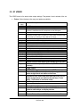
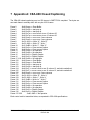
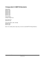
1
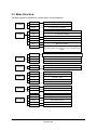
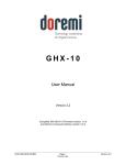
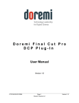
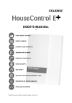
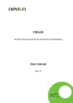
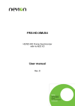
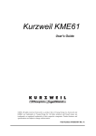
HDG-20 Portable HD-Video Test Generator User Manual Version 1.6 The English version of this document is the only legally binding version. Translated versions are not legally binding and are for convenience only. Compliant with HDG-20 Firmware Version 2.50 (03/2010) HDG.OM.000248.DRM Page 1 of 24 Doremi Labs Version 1.6 TABLE OF CONTENT 1 Introduction............................................................................................................................. 4 1.1 Contact Information............................................................................................................4 2 Menu and Navigation.............................................................................................................. 5 3 How to Use the HDG-20..........................................................................................................6 3.1 Display Mode..................................................................................................................... 6 3.2 Menu Mode........................................................................................................................ 6 3.3 Menu Structure:................................................................................................................. 7 3.4 00 FORMAT....................................................................................................................... 8 3.5 01 VIDEO........................................................................................................................... 9 3.6 02 AUDIO......................................................................................................................... 11 3.6.1 Testing Audio to Video delay ....................................................................................11 3.7 03 MOTION...................................................................................................................... 11 3.8 04 GENLOCK.................................................................................................................. 11 3.9 05 ANC DATA.................................................................................................................. 12 3.10 06 SYSTEM................................................................................................................. 12 4 Operational Hints.................................................................................................................. 14 4.1 Circle and Target patterns................................................................................................14 4.2 Crosshatch....................................................................................................................... 14 4.3 Border Lines..................................................................................................................... 14 4.4 Burn In Window................................................................................................................ 14 4.5 Genlock parameters.........................................................................................................14 5 Specifications........................................................................................................................ 15 5.1 Power............................................................................................................................... 15 5.2 Sync Input........................................................................................................................ 15 5.3 RS422 Serial.................................................................................................................... 15 5.4 HD/SD SDI....................................................................................................................... 15 6 The HDG-20 Control Panel application:..............................................................................16 6.1 HDG Unit Status............................................................................................................... 16 6.2 Quick Settings.................................................................................................................. 16 6.3 Communication Port Status..............................................................................................17 6.4 Format............................................................................................................................. 17 6.5 Genlock............................................................................................................................ 17 6.6 Video................................................................................................................................ 17 6.7 Audio / Ancillary Data.......................................................................................................17 6.8 System Settings............................................................................................................... 17 6.8.1 Firmware Upgrade.....................................................................................................18 6.8.2 License Information...................................................................................................18 6.8.3 Quick Pattern Access................................................................................................18 6.8.4 Scrolling Title............................................................................................................. 18 7 Appendix A: CEA-608 Closed Captioning...........................................................................19 8 Appendix B: Time Code........................................................................................................20 9 Appendix C: Audio................................................................................................................ 21 10 Appendix D: SMPTE Standards........................................................................................22 11 Appendix E: VANC Counter..............................................................................................23 12 Document Revision History..............................................................................................24 HDG.OM.000248.DRM Page 2 of 24 Doremi Labs Version 1.6 Software License Agreement The software license agreement can be found at the following location: http://www.doremilabs.com/support/proav-support/proav-warranties/ Hardware Warranty The hardware warranty can be found at the following location: http://www.doremilabs.com/support/proav-support/proav-warranties/ HDG.OM.000248.DRM Page 3 of 24 Doremi Labs Version 1.6 1 Introduction The HDG-20 is an HD/SD SDI test pattern generator with optional genlock capabilities. In addition to video test patterns, the HDG-20 can also output: 16 channels of embedded audio Ancillary Timecode, LTC and VITC Closed Caption, CEA-608 Standard and CEA-708 optional Moving objects or moving patterns Custom Scrolling text message Timecode burn in window VANC counter. 1.1 Contact Information If in need of help or assistance, please contact Doremi Labs Technical Services at + 1-818-5621101 or email at [email protected]. HDG.OM.000248.DRM Page 4 of 24 Doremi Labs Version 1.6 2 Menu and Navigation The HDG-20 has a new user interface. Menu selections are no longer active as soon as you change them, you must press ENTER to make the change. The HDG-20 has two modes: Menu mode and Display mode. In Menu mode the user can change the HDG-20 parameters In Display mode, the HDG-20 will show information about the output signal and genlock status In Menu mode, the HDG-20 has 3 levels: Main: Selects the Main menu that has the parameter to change. Menu 02 Audio Sub: Selects the parameter to change. The “#” sign at the end of the second line can be used to identify level 2 Menu-02 AUDIO Mode: On 1KHz# Selection: Make the change. The “*” sign shows the current value. When you hit the UP or DOWN arrows, the “*” will go away until you hit ENTER. Menu-02 AUDIO Mode: On 1KHz* The HDG-20 powers up in Display mode. To go to Menu mode, press the MENU button. UP and DOWN buttons will browse all available selection at that level. ENTER will make the selection and every time you press MENU it will go back one level until you get to Display mode. HDG.OM.000248.DRM Page 5 of 24 Doremi Labs Version 1.6 3 How to Use the HDG-20 On power up the HDG-20 displays the firmware version number for 2 seconds, then it goes in Display Mode. 3.1 Display Mode In Display Mode, the HDG-20 shows information about the output of the unit. It basically displays the output resolution, outputs mode, pattern and genlock status. The picture below shows the display after a factory reset. Resolution Outputs NTSC A = B SMPTEBar INTERN. Pattern Genlock Status When Quick Access in the SYSTEM menu is ON, pressing the UP and DOWN buttons in Display Mode will navigate through the available test patterns. 3.2 Menu Mode Refer to the next paragraphs on how to change any parameter; in this paragraph the example would be how to change the output resolution to 1080i: 1. Hit MENU to go in Menu Mode 2. Use the UP or DOWN buttons to get to “00 FORMAT”, then hit ENTER 3. Use the UP or DOWN buttons to get to “Resolution”, then hit ENTER 4. Use the Up or DOWN buttons to find 1080i, then hit ENTER 5. Hit MENU several times until you exit to Display Mode. HDG.OM.000248.DRM Page 6 of 24 Doremi Labs Version 1.6 3.3 Menu Structure: The Menu system is structured in 3 levels: Main, Sub and Selection. 00 FORMAT 01 VIDEO 02 AUDIO 03 MOTION 04 GENLOCK 05 ANC DATA 06 SYSTEM HDG.OM.000248.DRM Resolution NTSC, PAL, 720p, 1080i, 1080p, 2K sf, 2K p Frame Rate 23.98, 24, 25, 29.97, 30 Outputs A=B, Dual YPbPr, Dual RGB Pattern Look for the test patterns list later in this manual Title Off, On-White, On-Black TC BIW Off, On-W/B, On-B/W Filter Off, On BIW H BIW horizontal position BIW V BIW vertical position Color/YCbCr If a solid pattern is selected, the Color selection will appear. If a custom pattern is selected, the Y, Cb, Cr selections will appear Mode 1KHz-16KHz in 1KHz increments, Mult., Off Group 1, 2, 3, 4, 1+2, 3+4, 1+2+3+4 Level Silence,-42,-36,-30,-24,-20,-18,-12,-6, random, Flash Mask 1, 2, 3, 4, 1+2, 3+4, 1234 Mode No Motion, Sq1, Sq2, 2 Sqs, Sqs Inv, Full Motion, Snow Speed 1, 2, 3, 4, 5, 6, 7 Mode Off, On Input Displays the Genlock Input Format H Trig Changes in pixels V Trig Changes in lines Inv Fields Off, ON CC Closed Caption: Off, 608, 708 (option) TC Off, On/Non Drop, On/Drop VANC Off, On/1, On/12, On/123, On/1234 Version Displays the current version S/N Displays the serial number Save Save settings to flash Reset Reset factory settings Quick Acess Off, On Page 7 of 24 Doremi Labs Version 1.6 3.4 00 FORMAT The FORMAT menu allows you to change the video format parameters: Resolution: NTSC, PAL, 720p, 1080i, 1080p, 2K sf, 2K p. 2K resolutions are 2048x1080 at 23.98 or 24 FPS. “sf” and “p” designate segmented frame and progressive respectively. Frame Rate: 23.98, 24, 25, 29.97, 30 (50, 59.94, 60 for 720p formats) Outputs: The unit can output either the same signal on both output connectors, or a dual link YPbPr or RGB signal. The 4:4:4 dual link signal is compliant with the SMPTE 372 and SMPTE 352 standards. HDG.OM.000248.DRM Page 8 of 24 Doremi Labs Version 1.6 3.5 01 VIDEO The VIDEO menu is for actual video output settings: Test pattern, burn in window, title, etc. Pattern: Select between the many test patterns available. Pattern Label SMPTEBar 100%Bars Chkfield Cross H. Brd line Gradient Gray lev Grn lev Blu lev Red lev White Red Green Blue Gray 15% Gray Black Noise Circle Target 4/3 Target 16/9 Pluge RP219 V lines H lines M-Burst CHR-BRST G-H-Lev CB-Red Custom1 HDG.OM.000248.DRM Pattern Description SMPTE color bars 100% color bars The Checkfield pattern can be used to test the SDI clock recovery because it maximizes the DC component on the SDI signal. Cross Hatch is a white cross hatch on a black background Border Lines can be used to find if a device is displaying all lines and pixels. It has 8 colors, 2 pixels (or 2 lines) each to make a total of 16 pixels (or 16 lines) on every side of the image. Gradient is a 10 bit gradient, from black to white Gray Levels has 16 bars of gray, from black to white Green Levels has 16 bars of green, from black to green Blue Levels has 16 bars of blue, from black to blue Red Levels has 16 bars of red, from black to red 100% IRE White Pattern Red Pattern, use color parameter to go from 0% to 100% IRE Green Pattern, use color parameter to go from 0% to 100% IRE Blue Pattern, use color parameter to go from 0% to 100% IRE 25% Gray is 25% IRE gray pattern 15% Gray is 15% IRE gray pattern Black is 100% IRE black pattern White Noise can be used to test video compression Circle is also known as Moire pattern Perfect circle for non square pixel formats (NTSC & PAL) Perfect circle for square pixel formats (All HD and 2K formats) Pluge Pattern SMPTE RP219 pattern, also known as ARIB Vertical Lines. Black and white alternate every pixel to make straight black and white vertical lines Horizontal Lines. Black and white alternate every line to make straight black and white horizontal lines (1 field white, 1 field black in interlaced mode) Multiburst Chroma Burst pattern Green Horizontal Levels Color Bars with Red bottom. Use with Full Motion to test video to audio delays on display devices Custom Pattern #1, use Y,Cb,Cr parameters to define a Page 9 of 24 Doremi Labs Version 1.6 Custom2 Custom3 Random solid color custom pattern Custom Pattern #2, use Y,Cb,Cr parameters to define a solid color custom pattern Custom Pattern #3, use Y,Cb,Cr parameters to define a solid color custom pattern Random cycles through all patterns. Each pattern stays for about 2 seconds. Title: Hide or show the scrolling text message called “Title” in two different colors and 2 different sizes. The Title moves from bottom to top at 2 pixels per frame. **Note: The Title text can be changed using the HDG20 Control Panel application. TC BIW: Hide or show the burn in window timecode display Filter: Set the filter ON for smoother transitions between colors. o Filter OFF: Color transitions are sharp, they occur on the next pixel. Filter ON: Color transitions are smooth; it takes few pixels until the change of color occurs. BIW H: Burn In Window horizontal position from 0% to 100% in 10% increments BIW V: Burn In Window vertical position from 0% to 100% in 10% increments Color: This selection shows up only when Pattern is set to Red, Green, Blue or Gray Y(10b): This selection shows up only when Pattern is set to Custom1, Custom2 or Custom3. It’s a 10bit value that can be between 4 and 1019. Use in conjunction with Cb and Cr to define your own custom single color pattern. Cb(10b): Same as Y(10b) Cr(10b): Same as Y(10b) o HDG.OM.000248.DRM Page 10 of 24 Doremi Labs Version 1.6 3.6 02 AUDIO Using the AUDIO menu, you can select the embedded audio group (1-4), the 1K-tone volume level in db, etc. 3.6.1 Mode: Set audio to 1KHz -16KHz tone in 1KHz increments, Mult. or off. In Mult. (Multiple Frequencies) mode, the unit will output 1KHz tone on audio channel 1, 2KHz tone on audio channel 2, …, 16KHz tone on audio channel 16. Group: Set the embedded audio Group to 1, 2, 3, 4, 1+2, 3+4 or 1+2+3+4. Group 1 designates audio channels 1-4, Group 2 is 5-8, Group 3 is 9-12 and Group 4 is 13-16. Level: Set the tone level from Silence to –6 db. o The “random” selection is used for audio to video delay testing (see below). o The Flash selection is used for audio to video delay testing (see below). Mask: In a group, the audio can be present on channel 1, channel 2, channel 3, channel 4, pair 1&2, pair 3&4 or on all 4 channels. Testing Audio to Video delay The HDG20 provides 3 different ways to test audio to video delays: Set the audio level to “Random”: The audio level changes every time Square 1 touches any of the sides. Set the audio level to “Flash”: A new square will be added in the center of the screen that goes white with an audible tone or silent black Set the Pattern to CB-Red and the Motion to Full: The red bar at the bottom of the color bars will move outwards and inwards silently then flashes to white with an audible tone. 3.7 03 MOTION Motion can be added to the video output. Moving square(s), Snow, Full Motion, etc can be selected. Motion is field based in interlaced formats and frame based in progressive formats. Mode: No Motion, Square 1, Square 2, 2 Squares, 2 Squares Inverted, Full Motion and Snow. o Square 1 keeps changing size as it moves and it changes color when it hits any of the sides. Possible colors are: white, yellow, cyan, green, magenta, red, blue and black. Square 1 moves faster than square 2 o Square 2 is always blue and does not change size. It is slower than Square 1. o 2 Squares Shows both Square 1 and Square 2 o 2 Squares Inv shows both squares in inverted mode with a black background color. The pattern can be seen inside the squares. o Full Motion moves the whole pattern. Motion differs between patterns o Snow adds white noise to the video outputs. Speed: 1 is slowest, 7 is fastest. 3.8 04 GENLOCK HDG.OM.000248.DRM Page 11 of 24 Doremi Labs Version 1.6 Genlock is a software option that can be purchased through your dealer. A utility is provided that can be used with an authorization code to enable Genlock support. If Genlock is enabled on your unit you will have access to: Mode: On or Off Input: This is a display only selection that shows the Sync Input video format. H Trig: Sets the horizontal trigger value. Holding down the UP or DOWN buttons will cause the value to change faster and faster. The number is a pixel indication and can be moved from – half line to + half line. You don’t need to hit ENTER for this value to change. V Trig: Sets the vertical trigger value on lines. Inv Fields: On or Off. This parameter can be used to invert the field polarity of the output. The genlock input can accept any of the following signals: NTSC: For NTSC and all 29.97 and 59.94 FPS HD formats PAL: For PAL and all 25 and 50 FPS HD formats 1080i-29.97: For NTSC and all 29.97 and 59.94 FPS HD formats 1080i-25: For PAL and all 25 and 50 FPS HD formats 1080i-23.98: For 2K and all 23.98 FPS HD formats 1080i-30: For all 30 and 60 FPS HD formats 1080i-24: For 2K and all 24 FPS HD formats 3.9 05 ANC DATA Ancillary data can be used to embed metadata in the HD-SDI stream. Audio, Timecode, closed caption, etc. are all embedded in the ancillary data space. CC: Enables the closed caption on the ancillary data. The message output by the HDG20 is “Doremi” underlined followed by “HDG-20”. CC is compliant with CEA- 608 / SMPTE 334 and is placed on VANC data line 12. The HDG-20 also supports CEA-708 / SMPTE 334 closed caption as a paid option, it includes 608 caption packets and caption services 1 through 6. TC: Enables timecode on the ancillary data. For NTSC, 720p-59.94, 1080i-29.97 and 1080p-29.97, you can also decide if the timecode is drop or non-drop. For HD formats embedded LTC is compliant with SMPTE Standard RP-188. Timecode starts at 0 every time you change this selection or when it reaches 24 hours. The HDG-20 outputs LTC and VITC. VANC: Enables the VANC counter that adds 1, 2, 3 or 4 packets to the ancillary data. For more information on the packet content, refer to the VANC Counter Appendix at the end of this manual. 3.10 06 SYSTEM The SYSTEM menu can be used to show the current firmware version, save current settings to flash, reset factory defaults, etc. Version: Displays the current version number HDG.OM.000248.DRM Page 12 of 24 Doremi Labs Version 1.6 SN: Displays the serial number of the unit. Save Settings: Save the current settings to flash. Factory Reset: Reset the flash to factory defaults. ALL SAVED SETTINGS WILL BE LOST. Quick Access: Set to ON if you want to change the test pattern in Display Mode using the UP and DOWN buttons. HDG.OM.000248.DRM Page 13 of 24 Doremi Labs Version 1.6 4 Operational Hints 4.1 Circle and Target patterns The Target 16/9 pattern is based on a square pixel ratio for high definition formats. The Target 4/3 pattern is based on 11/10-pixel ratio in NTSC and 54/59-pixel ratio in PAL. The Circle pattern is based on a square pixel ratio for all formats. Since NTSC and PAL do not have a square pixel ratio, the circles will look like ellipses on standard definition CRT monitors. 4.2 Crosshatch Crosshatch pattern are usually made with 2 consecutive lines, one on each field. On the HDG product line we intentionally made the crosshatch with lines showing only on Field-1 so it can be used to identify problems related to field inversion. 4.3 Border Lines Border Lines can be used to find if a device is displaying all lines and pixels. It has 8 colors, 2 pixels (or 2 lines) each to make a total of 16 pixels (or 16 lines) on every side of the image. 4.4 Burn In Window The Burn In Window shows the timecode in 00:00:00:00 format. The character separating the seconds from the frames can be used to identify Field-1 from Field 2 for interlaced formats. It can also be used to identify drop and non-drop formats. Example: 00:00:01.04 indicates a non drop timecode for Field-1 interlaced 00:00:01:04 indicates a non drop timecode for Field-2 interlaced 00:00:01,04 indicates a drop frame timecode for Field-1 interlaced 00:00:01;04 indicates a drop frame timecode for Field-2 interlaced 4.5 Genlock parameters Each video format has its own set of HTRIG, VTRIG and Inv Fields values. They are saved to flash using the 06 SYSTEM > Save Settings sub-menu. If you use a bi-level sync source and keep switching between NTSC and 1080i for example, you don’t need to keep adjusting the H and V settings every time you change the output. You would adjust each format, with that same input, once, and save the settings to flash. Changing the Sync input signal format will require re-adjusting the H and V values. HDG.OM.000248.DRM Page 14 of 24 Doremi Labs Version 1.6 5 Specifications 5.1 Power Locking Power Connector DC Input: +5V to +18 V Consumption: 3.5VA 5.2 Sync Input BNC: Internally terminated with 75-OHM Accepts interlaced formats only (progressive formats can be genlocked to interlaced signals with the same frame rate) 5.3 RS422 Serial MiniDIN8: RS422. To connect to a PC with an RS232 COM port, use the cable provided with your unit. The pinout of the adapter cable is illustrated below: 5.4 HD/SD SDI SD-SDI: 270 Mbits/sec SMPTE 125M HD-SDI: 1.485/1.4835 Gbits/sec, SMPTE 274M, SMPTE 296M and SMPTE 372M HDG.OM.000248.DRM Page 15 of 24 Doremi Labs Version 1.6 6 The HDG-20 Control Panel application: The HDG-20 comes with a Windows XP / Vista compatible application that can be used to control the HDG-20 and upgrade its firmware. To use this application, you need to download it from our web site, install it, connect the provided RS422 to RS232 cable adapter between the unit and an available COM port on your PC then run the application. When you run the application for the first time, you will need to visit the Settings menu, select Connect To and select the COM port that you are connected to. 6.1 HDG Unit Status This section mimics the display mode of the HDG-20 front panel. 6.2 Quick Settings You can save your current settings to a file and assign it to any of the 8 buttons. To recall the settings, just press the assigned function key from your keyboard or click on any of the 8 buttons. HDG.OM.000248.DRM Page 16 of 24 Doremi Labs Version 1.6 6.3 Communication Port Status This LED will be red for no connection, yellow during search and green when a connection is established. 6.4 Format This tab will give you access to all available video formats. 6.5 Genlock This tab will allow you to set the Genlock parameters of the unit if you have that option. 6.6 Video This tab can be used to change all video parameters including pattern, motion, title, BIW, etc. 6.7 Audio / Ancillary Data This tab provides access to audio and ancillary data parameters including groups, audio levels, Closed Caption, etc. 6.8 System Settings This window can be accessed from the Settings menu: The top portion shows the units current firmware and serial number HDG.OM.000248.DRM Page 17 of 24 Doremi Labs Version 1.6 6.8.1 Press “Save Settings To Flash” if you want your current settings to be saved as the default after boot. Press the “Reset Factory Default” button to restore the factory defaults. Firmware Upgrade When you connect to the HDG-20 for the first time, the application will automatically detect that you have an earlier firmware on your unit and ask you to upgrade, you should accept. Once the upgrade is over and you see the message “Recycle power on the HDG-20 unit”, you can recycle the power. MAKE SURE YOU DON”T DISTURB THE UNIT DURING THE UPGRADE PROCEDURE AND WAIT FOR THE RECYCLE POWER MESSAGE, OTHERWISE THE UNIT MIGHT BECOME UNUSABLE AND YOU WILL NEED TO SEND IT BACK TO THE FACTORY FOR AN UPGRADE. If you want to do a manual firmware upgrade, you can browse for the firmware’s binary file (it would be something like: HDG20_2_44.bin) and then hit “Execute Upgrade” 6.8.2 License Information There are two available licenses that you can purchase: Genlock and CEA-708. When you purchase any of these licenses, you will be sent a code that you can copy paste into the license number field and hit “Update License” to update the license information on the unit and be able to use the new features. 6.8.3 Quick Pattern Access If you set this parameter ON, you can use the up and down arrows on the front panel of the HDG-20 to change the pattern while in Display mode. If you want the change to be permanent, make sure you click on “Save Settings to Flash” 6.8.4 Scrolling Title The HDG-20 has 4 lines of scrolling title that can be customized, Click on “Read from device” to read the text from the unit into the text boxes Click on “Write to device” to write the text from the text boxes into the device Click on “Save File” to save the text from the text boxes into a .txt file Click on “Open File” to load a .txt file into the text boxes Write up to 32 characters per line, then HDG.OM.000248.DRM Page 18 of 24 Doremi Labs Version 1.6 7 Appendix A: CEA-608 Closed Captioning The CEA-608 closed captioning sent on SDI stream is SMPTE 334 compliant. Two bytes are sent each frame in ancillary data, with a cycle of 251 frames: Frame 0 : 0x94, 0xae => Clear Buffer Frame 1 : 0x94, 0xae => Clear Buffer Frame 2 : 0x94, 0x20 => start pop up Frame 3 : 0x94, 0x20 => start pop up Frame 4 : 0x94, 0x7a => move cursor to row 15 column 20 Frame 5 : 0x94, 0x7a => move cursor to row 15 column 20 Frame 6 : 0x94, 0xa2 => move over 2 more columns Frame 7 : 0x94, 0xa2 => move over 2 more columns Frame 8 : 0xC4, 0xC8 => Write “H” , Write “D” Frame 9 : 0xC9, 0x20 => Write “G” , Write “ ” Frame 10 : 0x31, 0xB0 => Write “1” , Write “0” Frame 11 : 0x94, 0x2c => Clear current Caption Frame 12 : 0x94, 0x2c => Clear current Caption Frame 13 : 0x80, 0x80 => No operation Frame 14 : 0x80, 0x80 => No operation Frame 15 : 0x94, 0x2f => Display Caption Frame 16 : 0x94, 0x2f => Display Caption Frame 17–119: 0x80, 0x80 => No operation Frame 120 : 0x94, 0xae => Clear Buffer Frame 121 : 0x94, 0xae => Clear Buffer Frame 122 : 0x94, 0x20 => start pop up Frame 123 : 0x94, 0x20 => start pop up Frame 124 : 0x94, 0xf7 => move cursor to row 15 column 12, and write underlined Frame 125 : 0x94, 0xf7 => move cursor to row 15 column 12, and write underlined Frame 126 : 0x94, 0xa2 => move over 2 more columns Frame 127 : 0x94, 0xa2 => move over 2 more columns Frame 128 : 0xC4, 0xC8 => Write “D” , Write “o” Frame 129 : 0xC9, 0x20 => Write “r” , Write “e” Frame 130 : 0x31, 0xB0 => Write “m” , Write “i” Frame 131 : 0x94, 0x2c => Clear current Caption Frame 132 : 0x94, 0x2c => Clear current Caption Frame 133 : 0x80, 0x80 => No operation Frame 134 : 0x80, 0x80 => No operation Frame 135 : 0x94, 0x2f => Display Caption Frame 136 : 0x94, 0x2f => Display Caption Frame 137–250 : 0x80, 0x80 => No operation Each control code is transmitted twice, as requested in CEA- 608 specifications. HDG.OM.000248.DRM Page 19 of 24 Doremi Labs Version 1.6 8 Appendix B: Time Code Ancillary Timecode (ATC) is similar to linear time code (LTC). ATC is incremented each frame and is reset to 0 after 24 hours. LTC is on Line-10 Field-1 and VITC is on Line-9 Field-1 and on Line-571 Field-2. LTC is transmitted on Line-10 Field-1 for all formats except for PAL where it’s transmitted on line 6. (SMPTE RP188) VITC is transmitted on Line-9 Field-1 and Line-571 Field-2. HDG.OM.000248.DRM Page 20 of 24 Doremi Labs Version 1.6 9 Appendix C: Audio In SD (PAL or NTSC), 2 pairs are embedded on the SDI stream with 6 or 8 packets per line (SMPTE 272M). In HD, 2 pairs are embedded on the HDSDI stream (SMPTE 299M). HDG.OM.000248.DRM Page 21 of 24 Doremi Labs Version 1.6 10 Appendix D: SMPTE Standards Video Output SMPTE 125M SMPTE 292M SMPTE 296M SMPTE 274M SMPTE 372M SMPTE 352M Closed Caption CEA-608 / SMPTE 334 Time Code (LTC) SMPTE RP 188 Audio (embedded on SDI / HD-SDI) SMPTE 272M SMPTE 299M Note: In 2K, ancillary data is output only on Link A to match SMPTE 372M specifications. HDG.OM.000248.DRM Page 22 of 24 Doremi Labs Version 1.6 11 Appendix E: VANC Counter For 1080i-59.94 formats, when VANC is enabled, the HDG-20 can embed up to 4 data packets on each of the following lines: Field-1: Lines 9 to 20 Field-2: Lines 572 to 583 All packets are identical except for UDW0, UDW1 and CS that are used to indicate the line number, packet number / field identifier and the checksum. The packet is structured as follows: ADF1= 0x00 ADF2= 0xFF ADF3= 0xFF DID= 0x5F SDID= 0xFA DC= 0xFF UDW0= LSB byte of the line number UDW1= Packet Number and Field Identifier, 0x30 for packet-3 field-1 or 0x2F for packet-2 field-2 UDW2 .. UDW254= Hex value of a counter that starts at 0x00 and ends 0xFC CS= Checksum HDG.OM.000248.DRM Page 23 of 24 Doremi Labs Version 1.6 12 Document Revision History Date Version 07/26/2012 1.5 Logo and contact information updated. 05/06/2014 1.6 Minor editorial changes made. HDG.OM.000248.DRM Description Page 24 of 24 Doremi Labs Version 1.6