1
No.99MBC034B4
SERIES No.542
EV Counter
Linear Gage
Counter
User’s Manual
Read this User’s Manual thoroughly
before operating the instrument. After reading,
retain it close at hand for future reference.
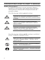
CONVENTIONS USED IN USER' S MANUAL
Safety Precautions
To operate the instrument correctly and safely, Mitutoyo
manuals use various safety signs (Signal Words and Safety
Alert Symbols) to identify and warn against hazards and
potential accidents.
The following signs indicate general warnings:
DANGER
Indicates an imminently hazardous situation
which, if not avoided, will result in serious injury
or death.
CAUTION
Indicates a potentially hazardous situation
which, if not avoided, could result in serious
injury or death.
WARNING
Indicates a potentially hazardous situation
which, if not avoided, may result in minor or
moderate injury or property damage.
The following signs indicate specific warnings or prohibited
actions, or indicate a mandatory action:
Alerts the user to a specific hazardous situation.
The given example means " Caution, risk of
electric shock" .
Prohib its a specific action. The given example
means " Do not disassemb le" .
Specifies a req uired action. The given example
means " Ground" .
i
CONVENTIONS USED IN USER' S MANUAL
On Various Types of Notes
The following types of notes are provided to help the operator
obtain reliable measurement data through correct instrument
operation.
IMPORTANT
• An important note is a type of note that
provides information essential to the completion of a task. You cannot disregard this note
to complete the task.
• An important note is a type of precaution,
which if neglected could result in a loss of
data, decreased accuracy or instrument
malfunction/failure.
NOTE
A note emphasizes or supplements important
points of the main text. A note supplies
information that may only apply in special cases
(e.g.. Memory limitations, eq uipment configurations, or details that apply to specific versions of
a program).
TIP
A tip is a type of note that helps the user apply
the techniq ues and procedures describ ed in the
text to their specific needs.
It also provides reference information associated with the topic b eing discussed.
Mitutoyo assumes no liability to any party for any
loss or damage, direct or indirect, caused by use
of this instrument not conforming to this manual.
Information in this document is subject to change
without notice.
© Copyright Mitutoyo Corporation. All rights
reserved.
ii
PRECAUTIONS
To obtain the optimum performance from it, obey the
following precautions
WARNING
• Neither remove the cover nor disassemble
this counter.
Doing so may expose personnel to electric
shock or result in damage or fire to this
counter due to a short circuit caused by metal
chippings or dust.
• Note the warning labels on the top surface of
this counter.
• This counter is a precision instrument. Do not
bump or apply excessive force to any part of
this counter when setting it up or operating it.
• Use this counter in an environment where the
temperature is between 0°C and 40°C. The
temperature variation should be minimized so
there is no condensation.
• Avoid operating this counter in the following
places:
where it will be exposed to cutting chips and
oil, dirt, dust, or significant vibrations,
where it will be exposed to direct sunlight,
or near high-voltage/large current power
equipment.
iii
WARRANTY
In the event that the Mitutoyo EV Counter should prove
defective in workmanship or material, within one year from
the date of original purchase for use, it will be repaired or
replaced, at our option, free of charge upon its prepaid return
to us.
This warranty shall not apply if the product has been subject
to fair wear and tear, abuse through misuse or improper use/
handling/storage/maintenance/service/repair or through
adaptation/modification by the original purchaser or any third
party without prior written consent of Mitutoyo or as a result
of damage by an actual disaster or circumstances beyond the
control of Mitutoyo.
To obtain service under this warranty the product must be
returned to the nearest Mitutoyo Service Center. Any postage,
insurance, or shipping charges incurred in returning the
product for service are the responsibility of the purchaser.
* This warranty is not transferable and is only valid within
the country of the original purchase.
* You may have additional rights under the laws of country
of original purchase that do not allow the exclusion of
implied warranties or the exclusion or limitation of certain
damages. If these laws apply, Mitutoyo's limitations and
exclusions may not apply to you.
iv
CONTENTS
CONVENTIONS USED IN USER'S MANUAL .......i
PRECAUTIONS ................................................... iii
WARRANTY .........................................................iv
1 OVERVIEW .................................................... 1-1
1.1 EV Counter ......................................................1-1
1.1.1 Features.......................................................... 1-1
1.1.2 Name and dimensions of each part ................ 1-2
1.2 D-EV External Display Unit (optional) .............1-5
1.2.1 Features.......................................................... 1-5
1.2.2 Name and dimensions of each part ................ 1-5
1.3 Internal Block Diagram ....................................1-7
2 SETUP ........................................................... 2-1
2.1 Installing the EV Counter.................................2-1
2.2 Connecting Cables ..........................................2-2
2.2.1 Connecting gages ........................................... 2-2
2.2.2 Connecting the D-EV (External Display Unit) ............ 2-3
2.2.3 RS-232C, I/O/BCD, and RS LINK connections .......... 2-3
2.2.4 Connecting the power supply and grounding .............. 2-3
2.3 Power On .........................................................2-4
3 SETTING PARAMETERS .............................. 3-1
3.1 Setting Parameters (with D-EV) ......................3-1
3.1.1 Parameter mode ON ...................................... 3-1
3.1.2 Specifying the gage resolution (for EV-16P and EV-16Z) .......3-2
3.1.3 Setting the axes to be used ............................. 3-2
3.1.4 Parameter mode OFF ..................................... 3-3
3.1.5 List of parameters .......................................... 3-4
3.2 Setting Parameters (with EV Counter) ............3-6
3.2.1 Parameter mode ON ...................................... 3-6
3.2.2 Setting the parameters ................................... 3-7
3.2.3 Parameter mode OFF ..................................... 3-7
3.2.4 List of parameters .......................................... 3-8
v
CONTENTS
4 BASIC OPERATION ...................................... 4-1
4.1 Power ON Precautions .................................. 4-1
4.2 Switching the Display/Output CH (with D-EV) .................. 4-2
4.3 Switching the Peak Mode (with D-EV) ........... 4-4
4.4 Clearing the Peak Value (with D-EV) ............. 4-5
4.5 Input of Preset Value/Tolerance Value (with D-EV) ......... 4-6
4.6 Clearing the Error State ................................. 4-8
4.7 Presetting (with the D-EV) ............................. 4-9
4.8 Tolerance Judgment (with the D-EV) ........... 4-10
5 RS-232C COMMUNICATION FUNCTION ............ 5-1
5.1 RS-232C Connection ..................................... 5-1
5.2 RS-232C Output Specifications ..................... 5-1
5.2.1 Specifications of cables and connectors ....... 5-1
5.2.2 Communication specifications ..................... 5-1
5.2.3 Pin assignment ............................................. 5-2
5.2.4 List of available commands ......................... 5-2
5.2.5 RS-232C command and RS-232C response output ..... 5-5
5.2.6 HOLD input and RS-232C response output ................... 5-5
5.2.7 Time required for RS-232C data output ...... 5-6
6 RS LINK FUNCTION ..................................... 6-1
6.1 Connection Method ........................................ 6-1
6.2 Start-Up Method ............................................. 6-2
6.3 Troub leshooting ............................................. 6-3
7 I/O FUNCTION .............................................. 7-1
7.1 Overview of the I/O function ........................... 7-1
7.2 Connectors ..................................................... 7-1
7.3 Input/Output Circuit ........................................ 7-1
7.3.1 Output circuit ............................................... 7-1
7.3.2 Input circuit .................................................. 7-1
7.4 NORMAL Mode ............................................. 7-2
7.4.1 Overview of the NORMAL mode ............... 7-2
7.4.2 Tolerance judgment output .......................... 7-2
7.4.3 BCD output .................................................. 7-4
7.4.4 Segment output ............................................ 7-6
7.5 Calculation Mode ......................................... 7-10
7.5.1 Overview of the calculation mode ............. 7-10
7.5.2 Tolerance judgment result output .............. 7-10
7.5.3 BCD output ................................................ 7-11
7.5.4 Segment output .......................................... 7-11
vi
CONTENTS
7.6 High-speed Mode ......................................... 7-12
7.6.1 Overview of the high-speed mode ............. 7-12
7.6.2 Tolerance judgment result output .............. 7-13
7.6.3 BCD output ................................................ 7-13
7.6.4 Segment output .......................................... 7-13
7.7 Timing Chart ................................................ 7-14
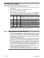
7.7.1 Power ON characteristics ........................... 7-14
7.7.2 Output period of tolerance judgment result ................. 7-14
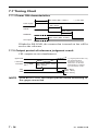
7.7.3 Data output ................................................. 7-15
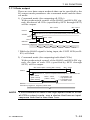
7.7.4 External presetting ..................................... 7-16
7.7.5 Designating CELs to be output/Specifying the
calculation method ....................................................... 7-17
7.7.6 Peak clear ................................................... 7-17
7.7.7 HOLD timing ............................................. 7-18
8 SPECIFICATIONS ......................................... 8-1
8.1 Specifications ................................................. 8-1
8.2 Standard Accessories .................................... 8-1
8.3 Optional Accessories ..................................... 8-2
8.4 List of Error Outputs ....................................... 8-3
SERVICE NETWORK
vii
1
OVERVIEW
This chapter outlines the features of the EV
Counter for linear gages.
1.1 EV Counter
1.1.1 Features
• Three models of EV counter (EV-16P, EV-16D, and EV-16Z) are
available according to the linear gage connected. The applicable
gages for each model are as follows.
EV-16P: LGF, LGB, and LGE series linear gage (excluding the models that output sine waves)
EV-16D: LGD and LGS series linear gage
EV-16Z: LGF-Z series linear gage
• EV counter is a multi-axis counter to which plural gages can be connected. The maximum number of gages that each model can connect
is 6.
Only EV-16Z supports the origin embedded gages.
• The origin function of EV-16Z realizes high-speed response and reduces the time and labor taken by referencing with a master each time
the power is turned on.
• With the RS LINK function a maximum of ten EV Counter units can
be linked. This makes it possible to construct a system consisting of a
maximum of sixty linear gages through one RS-232C port, which is
on, for example, a personal computer.
• The display unit is of a separate type (optional) which takes in-line
use into consideration.
• Depending on the external devices to be connected and uses, the following I/F connection and output mode can be selected:
[Connection I/F]
Tolerance judgment output
Separately outputs the judgment result from each CEL.
Segment output
Outputs the range specified by the external signal after evenly dividing it into ± ten stages.
The objective CEL to be output and its range can be specified with
the external SET signal.
BCD output
Output of sign and 6-digit data.
The objective CEL to be output can be designated with the external
SET signal.
RS-232C/RS LINK
A maximum of 10units/60 channels can be linked.
Preset and tolerance values can be remotely controlled.
Can be used simultaneously with other I/O devices.
[Output mode]
NORMAL mode (factory-set default)
Calculation mode
Calculate the sum, mean, maximum, minimum, and width between the specified CELs and outputs the results.
High-speed mode
Quickly outputs the specified CEL.
No. 99MBC034B
1-1
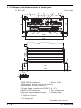
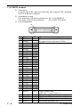
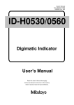
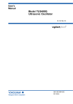
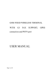
1.1.2 Name and dimensions of each part
1) EV-16P
Unit: mm
4
1
5
IN
E
OUT
D
3
Err.
4
5
4
LOAD 8 7 MODE 6
3
INPUT
C
10 11
SEL. 2 1 DATA
B
A
64
72
F
RS LINK
2
RS-232C
+V
IO/BCD
4
Code No.***-***
Model EV-16P
Code No.***-***
DC12-24V
700mA
6
MADE IN JAPAN
-V
6
4
7
136
9
8
4
144
11, 12
5
16
161
139
5
16
4.5
6.5
1. RS LINK connector
2. Error LED
3. Parameter input switch (4 pieces)
4. Parameter LED (8 pieces)
5. Gage input connector (INPUT A - F)
6. RS-232C connector
7. I/O connector
8. Power inlet terminal strip 9. Name plate
10. Junction bracket*
11. M4 x 8 screw*
12. Fixing leg*
* Standard accessory
1-2
No. 99MBC034B
1 OVERVIEW
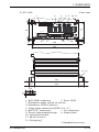
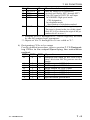
2) EV-16D
Unit: mm
4
1
2
IN
RS LINK
OUT
Err.
4 5 10 11
3
5
4
LOAD 8 7 MODE 6
3
E
SEL. 2 1 DATA
C
B
A
64
72
F
INPUT
D
RS-232C
+V
IO/BCD
4
Code No.***-***
Model EV-16D
Code No.***-***
DC12-24V
700mA
6
MADE IN JAPAN
-V
6
4
7
136
9
8
4
144
11, 12
5
16
161
139
5
16
4.5
6.5
1. RS LINK connector
2. Error LED
3. Parameter input switch (4 pieces)
4. Parameter LED (8 pieces)
5. Gage input connector (INPUT A - F)
6. RS-232C connector
7. I/O connector
8. Power inlet terminal strip 9. Name plate
10. Junction bracket*
11. M4 x 8 screw*
12. Fixing leg*
* Standard accessory
No. 99MBC034B
1-3
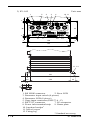
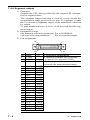
3) EV-16Z
Unit: mm
5
2
3
4
10 11
6
4
7
9
8
6
4
72
64
4
1
4
136
144
11, 12
5
16
161
139
5
16
4.5
6.5
1. RS LINK connector
2. Error LED
3. Parameter input switch (4 pieces)
4. Parameter LED (8 pieces)
5. Gage input connector (INPUT A - F)
6. RS-232C connector
7. I/O connector
8. Power inlet terminal strip 9. Name plate
10. Junction bracket*
11. M4 x 8 screw*
12. Fixing leg*
* Standard accessory
1-4
No. 99MBC034B
1 OVERVIEW
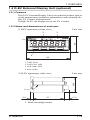
1.2 D-EV External Display Unit (optional)
1.2.1 Features
The D-EV External Display Unit is an optional product used to
set the measurement conditions (parameters) and externally display EV Counter measurements.
A single D-EV can display/set up one EV Counter.
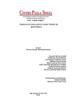
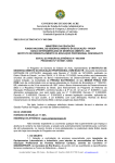
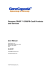
1.2.2 Name and dimensions of each part
1) D-EV appearance (front view)
Unit: mm
2
3
GAGE
1
MAX
UNIT
TIR
MIN
GO
48
+NG
-NG
DISP
4
Fn
MODE
P.SET
96
1. UNIT LED
2. GAGE No. LED
3. Peak mode LED
4. Key switch
Unit: mm
44.4
2) D-EV appearance (side view)
5
6.6
67
(11)
5. Panel-mounting bracket
No. 99MBC034B
1-5
3) D-EV appearance (rear view)
Code No.
Model
Serial No.
02ADD400
D-EV
000001
DC12-24V
MADE IN JAPAN
IN
6
7
Unit: mm
RS LINK
200mA
OUT
91.4
+V
-V
8
6. RS LINK connector
7. Name plate
8. Power inlet terminal strip
1-6
No. 99MBC034B
No. 99MBC034B
Gage D
Gage A
Gage E
Gage B
Gage F
Gage C
Gage
selector
Gage
selector
Origin and
tolerance setup
Peak measurement
Origin and
tolerance setup
Peak measurement
Origin and
tolerance setup
Peak measurement
Origin and
tolerance setup
Peak measurement
Origin and
tolerance setup
Peak measurement
Origin and
tolerance setup
Peak measurement
Internal counter
CEL6
CEL5
CEL4
CEL3
CEL2
CEL1
NORMAL mode
High-speed mode
Calculation
function
Calculation result
Tolerance judgment
MAX - MIN of
CELs
Minimum of
CELs
Maximum of
CELs
Mean of
CELs
Sum of
CELs
Calculation
mode
Internal counter
Tolerance
judgment
Segment
BCD
Simultaneously
RS-232C
Output function
CEL designation
I/O output
Tolerance judgment output
Segment output
BCD output
CEL designation
Peak mode switching
Zero-setting
Presetting
Peak clear
Tolerance value input
1 OVERVIEW
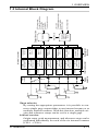
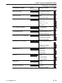
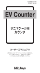
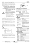
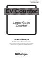
1.3 Internal Block Diagram
Gage selector:
By setting the appropriate parameters it is possible to connect a single gage output either to one internal counter or to
multiple internal counters. With this function, multiple origins and tolerance setups can be set for a single gage.
Internal counter:
Origin setup, peak measurement, and tolerance setup can be
performed individually for each of the six internal counters
(CEL1 - CEL6).
1-7
Calculation function:
Each of the internal counters has a specific calculation function. Therefore, calculation can be performed between the
counters specified by the parameters.
Output function:
Either RS-232C, BCD, tolerance judgment, or segment output can be selected. The objective CEL to be output can be
selected using the RS-232C command or SET signal.
1-8
No. 99MBC034B
2
SETUP
This chapter describes the method used to install and connect the EV Counter and make its
initial conditions.
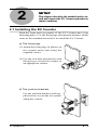
2.1 Installing the EV Counter
Both the front and rear panels of the EV Counter have four
mounting holes. Use the fixing legs and junction brackets which
come as the standard accessories to install the EV Counter.
a) The fixing legs
(1) Attach the fixing legs (4 places) on
the counter main unit using the
supplied screws.
(2) Use the oval hole provided on each
fixing leg to secure the counter to
an appropriate surface.
b) The junction brackets
Use the junction brackets and supplied screws to join the two panels
along the vertical.
No. 99MBC034B
2-1
2.2 Connecting Cables
IMPORTANT • Connection should be made only after the
power to the main unit and to the partner device
of the connection have been turned off. Otherwise, the counter main unit and the connected
device will be damaged.
• Use a 12 - 24VDC power supply with a control
output current of 1A or greater. Do not draw
power from a source which is used by highpower equipment.
• Do not route the power cable, I/O cable, RS232C cable, RS LINK cable, or gage connection cable with other power cables.
• Use a shielded I/O cable not longer than 3m.
• Always ground.
• Each cable should be secured (to, for example,
the main body of the device).
2.2.1 Connecting gages
(1) Sequentially connect the required number of linear gages to
the corresponding connectors, starting with the INPUT A
connector.
(2) If the EV-16P or EV-16Z is connected to a gage that does
not have a resolution of 1µm, refer to section 3.1 Setting
Parameters (with D-EV) and section 3.2 Setting Parameters (with EV Counter) to adjust the resolution.
NOTE
• The gage resolution has been factory-set to 1mm.
• It is not necessary to modify the resolution on the EV16D.
(3) Set the parameter for designating available axes according
to the number of gages to be connected.
(Refer to section 3.1 Setting Parameters (with D-EV) and
section 3.2 Setting Parameters (with EV Counter)).
2-2
No. 99MBC034B
2 SETUP
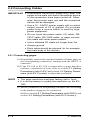
2.2.2 Connecting the D-EV (External Display Unit)
If a D-EV (External Display Unit) is used, make the necessary
connections according to the following procedure.
(1) Connect the RS LINK OUT connector of the EV Counter to
the RS LINK IN connector of the D-EV using an RS LINK
connection cable.
EV Counter
RS LINK
IN
OUT
RS LINK
IN
OUT
D-EV
RS-232C
NOTE
RS LINK
connecting
cable (optional)
Always use the RS LINK connection cable specified by
Mitutoyo. Refer to section 8.3 Optional Accessories.
(2) To link more than one counter with the RS LINK connection cables, refer to chapter 6 RS LINK FUNCTION.
TIP
The D-EV will display the data of the EV Counter which
is connected to the RS LINK IN connector of the D-EV.
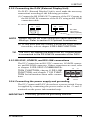
2.2.3 RS-232C, I/O/BCD, and RS LINK connections
The EV Counter has an RS-232C connector, I/O/BCD connector, and RS LINK connector. If these connectors are used, refer
to chapter 5 RS-232C COMMUNICA+V -V
TION FUNCTION; chapter 6 RS LINK
FUNCTION; and chapter 7 I/O FUNCTION for information about cable connections.
DC12-24V
700mA
2.2.4 Connecting the power supply and grounding
The EV Counter and D-EV do not have a power switch. Power
is supplied by connecting the power source to the +V and -V
terminals on the power inlet terminal strip.
IMPORTANT Positively ground the grounding terminal.
No. 99MBC034B
2-3
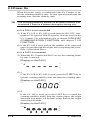
2.3 Power On
When the power source is connected to the EV Counter, it enters the counting stand-by state. To start operation and enter the
counting state, quit the stand-by state.
TIP
The counting stand-by function is an alarm function that
is entered if there is a power interruption during use.
a) If a D-EV is not connected
(1) If the EV-16P or EV-16D is used,enter the RS-232C command or I/O signal (a HOLD signal to clear the error) in the
EV Counter. For information refer to chapter 5 RS-232C
COMMUNICATION FUNCTION; and chapter 7 I/O
FUNCTION.
(2) If the EV-16Z is used, push in the spindles of all connected
gages to pass through the origins after completing the procedure (1) described above.
b) If a D-EV is connected
(1) When the EV Counter and D-EV are on, the counting standby state is entered.
[Display on the D-EV]
UNIT
+NG
GO
-NG
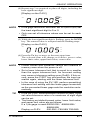
(2)-1
If the EV-16P or EV-16D is used, press the P.SET key to
quit the counting stand-by state and enter the counting state.
[Display on the D-EV]
UNIT
+NG
GO
-NG
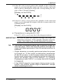
(2)-2
If the EV-16Z is used, press the P.SET key to cancel the
counting stand-by mode, then the counter enters the origin
detection wait mode. All decimal points flash in the origin
detection wait mode.
[Display on the D-EV]
UNIT
+NG
GO
-NG
2-4
No. 99MBC034B
2 SETUP
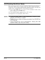
(3) If the EV-16Z is used, push in the spindle of the connected
gages to pass through the origin one after another, and each
time it passes through the origin the corresponding bar display of the CH starts flashing.
[Display on the D-EV]
UNIT
+NG
GO
-NG
(4) If the EV-16Z is used, push in the spindles of all connected
gages to pass through the origins, then the counter enters the
counting mode.
[Display on the D-EV]
UNIT
+NG
GO
-NG
c) Precautions in using the EV-16Z
If the EV-16Z is used, note the following precautions.
IMPORTANT Be sure to pass the spindle through the origin for
detection properly. If the spindle vibrates near the
origin, the origin may not be detected correctly.
TIP
• The origin-embedded gage has a specific origin inside the gage. When the spindle passes through the
origin the signal generates, then the preset position is
restored.
• Origin detection is usually performed when the power
is turned on. If the origin re-detection parameter
(P.No.42) is set to 1, the counter enters the origin detection wait mode after completing preset or tolerance
setup (for details, refer to the section, “3.1 Setting
Parameters (with D-EV)”), or when the HOLD signal
is triggered.
• If the HOLD signal is input again during origin re-detection, the counter resets origin re-detection, except
when resetting an error.
No. 99MBC034B
2-5
3
SETTING PARAMETERS
This chapter describes the method used to set
the parameters required to use the EV
Counter.
3.1 Setting Parameters (with D-EV)
Before using the EV Counter, various parameters must be set
up. This section explains the setup method using the essential
parameters, "gage resolution" (for EV-16P and EV-16Z) and
"designation of available axes", as examples.
NOTE
For the resolution of 0.1µm setting, a D-EV is absolutely
necessary.
3.1.1 Parameter mode ON
Set the parameter mode to ON to modify the existing parameter
settings.
(1) Press the P.SET key while holding down the Fn key to set
the parameter mode to ON.
[Display on the D-EV]
UNIT
+NG
GO
-NG
(2) Press the P.SET key one more time to modify the setup
value to 1.
[Display on the D-EV]
UNIT
+NG
GO
-NG
NOTE
If a parameter setting needs to be modified, first modify
the setting of Parameter 00 to 1. Parameter modification
cannot be attempted while the setting of Parameter 00 is
0 (Reference mode).
(3) Begin setting the parameters.
No. 99MBC034B
3-1
3.1.2 Specifying the gage resolution (for EV-16P and EV-16Z)
In order to connect a gage with a resolution that is not 1µm, the
counter must modify its resolution setting to that of the connected gage.
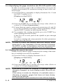
(1) Press the Fn key repeatedly to display Parameter No. 12 and
the INPUT number of A.
[Display on the D-EV]
UNIT
+NG
GO
-NG
(2) Press the P.SET key to modify the setup value. (Refer to
section 3.1.5 List of parameters.)
(3) If more than one gage is connected, repeat steps (1) and (2)
to set the resolution of all gages while sequentially switching the INPUT number by pressing the Fn key.
(4) To complete the setting operation press the P.SET key
while holding down the Fn key.
If the EV-16Z is used, push in the spindle to pass through
the origin.
In order to continue the setup operation for other parameters
simply press the Fn key.
NOTE
In order to modify the existing resolution setting, either
press the Fn key repeatedly until the desired Parameter
No./INPUT number is displayed or exit from the parameter
mode and start the setup operation from the beginning.
3.1.3 Setting the axes to be used
If there are less than six gages connected, the setting of the number of available axes must be modified.
(1) Press the Fn key to display Parameter No.13.
[Display on the D-EV]
UNIT
+NG
GO
-NG
(2) Press the P.SET key to modify the setup value. (Refer to
section 3.1.5 List of parameters.)
NOTE
3-2
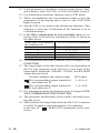
If the setup is made as (Number of available axes) >
(Number of gages), an error display/output (Error40) will
result.
If the setup is made as (Number of available axes) <
(Number of gages), gages that have not been designated will be ignored.
For information refer to section 8.4 List of Error Outputs.
No. 99MBC034B
3 SETTING PARAMETERS
(3) To complete the setting operation press the P.SET key
while holding down the Fn key. If the EV-16Z is used, push
in the spindle to pass through the origin.
In order to continue the setup operation for other parameters
simply press the Fn key.
TIP
Relationship between the parameter setup values and
available axes
An EV Counter has six internal counters (CEL 1 - 6).
Data of gages connected to the gage input connectors,
INPUT A - F, will be displayed/output as the data of CEL
1 - 6, respectively.
Available axes are designated by determining the relationship between INPUT A - F and CEL 1 - 6. The following table lists the possible combinations.
Setup value CEL1
1
2*1
3
4
5
6*2
INPUT A
INPUT A
INPUT A
INPUT A
INPUT A
INPUT A
CEL2
INPUT A
INPUT B
INPUT B
INPUT B
INPUT B
INPUT B
CEL3
INPUT A
INPUT A
INPUT C
INPUT C
INPUT C
INPUT C
CEL4
INPUT A
INPUT B
INPUT A
INPUT D
INPUT D
INPUT D
CEL5
INPUT A
INPUT A
INPUT B
INPUT A
INPUT E
INPUT E
CEL6
INPUT A
INPUT B
INPUT C
INPUT B
INPUT A
INPUT F
*1 :
If the setup value is "2", internal counters CEL1, 3, and 5 will
display/output the data of INPUT A. Internal counters CEL2, 4,
and 6 will display/output the data of INPUT B. By setting a different tolerance value for each of CEL1, 3, and 5, three different
types of tolerance judgments can be made from the data of INPUT A.
*2 : The factory-set default is "6".
3.1.4 Parameter mode OFF
(1) Press the P.SET key while holding down the Fn key to set
the parameter mode to OFF. If the EV-16Z is used, push in
the spindle to pass through the origin. The parameter setup
is modified and the Display Unit returns to the count value
display.
NOTE
• If the P.SET key is pressed during the setup operation
and while the Fn key is being held down, the setup
operation is interrupted and the count value display is
restored. (If the EV-16Z is used, push in the spindle to
pass through the origin.) If this occurs, the modifications made up to the interruption are reflected in actual operation.
• During parameter setup operation, the parameter input switch, RS-232C output, and external signal input
are all disabled.
No. 99MBC034B
3-3
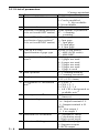
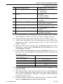
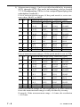
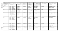
3.1.5 List of parameters
* Factory-set default
No. Parameter name
00 Reference/Modification
10 Parameter clear
11 Selection of counting direction
(to be set for each INPUT number)
12 Case of EV-16P or EV-16Z
Specification of gage resolution*1
(to be set for each INPUT number)
12 Case of EV-16D
Specification of gage type
13 Designation of available
axes*2
14 Start-up mode
15 Display unit*1
17 Designation of calculation
axis*4
20 I/O output mode*6
21 I/O output logic*7
22 Selection of I/O function*6
23 Selection of I/O type*6
3-4
Setup value: function
0*: For reference only
1: Can be modified
2: Not available
3: Not available
1: Resets to factory-set default
If the spindle is pushed-in
0*: + counting
1: - counting
0: 10µm gage
1: 5µm gage
2*: 1µm gage
3: 0.5µm gage
4: 0.1µm gage
0: INC (LGS series)
1*: ABS (LGD series)
2*: ABS ORG
6*: 6 gages are used
5: 5 gages are used
4: 4 gages are used
3: 3 gages are used
2: 2 gages are used
1: 1 gage is used
0*: Counting stand-by
1: Counting execution
0*: mm *3
1: E (=1/25.4 mm)
0*: CEL1, 2
1: CEL1, 2, 3
2: CEL1, 2, 3, 4
3: All CELs designated as
available axis*5
0: Command
1*: Interval
Tolerance judgment and segment
0*: Output terminal is L
1: Output terminal is H
BCD
0*: H at output 1
1: L at output 1
0*: NORMAL mode
1: Calculation mode
2: High-speed mode
0*: Tolerance judgment
1: Segment output
2: BCD output
No. 99MBC034B
3 SETTING PARAMETERS
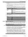
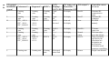
* Factory-set default
No. Parameter name
25 Baud rate*8, *9
26
27
28
41
42
43
Setup value: function
0: 4800 bps
1*: 9600 bps
2: 19200 bps
Parity*8, *9
0: None
1: Odd number
2: Even number
Data bits*8, *9
0*: 7 bits
1: 8 bits
HOLD selection*9
0*: HOLD
1: RS-232C output*10
Origin detect direction (EV-16Z only) 0*: origin detection at + count
1: origin detection at - count
Origin re-detection*11 (EV-16Z only) 0*: not detect
1: detect
Origin initialize (EV-16Z only) Starts with 0 from the origin.
1: initialize (one-shot)
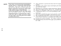
*1 : If this parameter is modified, each zero point, preset value,
and tolerance value for CEL1 to CEL6 will be cleared.
*2 : For information about this function refer to TIP on page 3-3.
*3 : This is not modified even if an attempt is made to clear the
parameters. If the display unit is set to E, the UNIT LED
lights in green.
*4 : Sets the CEL to be used for the calculation function. (This
function is valid only if Selection of I/O function is set to
Calculation mode.)
*5 : If all CELs designated as the available axis are selected, CELs to be used for calculation will be as shown in
the table below.
Setup value for designating CEL to be used for calculation
the available axes
6
1, 2, 3, 4, 5, 6
5
1, 2, 3, 4, 5
4
1, 2, 3, 4
3
1, 2, 3
2 or 1
1, 2
*6 : For information about this function refer to chapter 7 I/O
FUNCTION.
*7 : The output logic of the data section will vary depending on
the I/O type selection result. However, the logic of the input signal, NORMAL, READY, START, and EXTEND
output remains fixed.
*8 : For information about this function refer to chapter 5 RS232C COMMUNICATION FUNCTION.
No. 99MBC034B
3-5
*9 : The parameter modification will be made valid after resetting the power.
*10: This function will output data from the RS-232C connector
if a HOLD signal is input through the I/O connector. In this
case, all RS-232C commands will be ineffective.
*11: For details, refer to the section, "2.3 Power On".
3.2 Setting Parameters (with EV Counter)
Before using the EV Counter, various parameters must be set
up. The parameter setup operation is easily performed if a DEV is used.
IMPORTANT The EV-16Z can not modify the origin-related settings by itself. For making this modification in EV16Z, prepare a D-EV.
NOTE
• Use a D-EV for the resolution of 0.1µm setting.
Set up of EV Counter alone, is not possible.
• Only a D-EV allows setting when the modification is
made for the parameter no.41, 42, and 43.
• In order to connect a gage with a resolution that is not
1µm, the counter must modify its resolution setting to
that of the connected gage if the EV-16P or EV-16Z is
used.
• The gage type (INC, ABS, etc.) must be set for the
EV-16D.
• If the setup is made as (Number of available axes) >
(Number of gages), an error display/output (Error40)
will result.
If the setup is made as (Number of available axes) <
(Number of gages), gages that are not designated will
be ignored. For information refer to section 8.4 List of
Error Outputs.
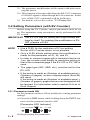
3.2.1 Parameter mode ON
Set the parameter mode to ON to modify the existing parameter
settings.
(1) Press the LOAD button while holding down the DATA button to set the parameter mode to ON.
[Parameter LED Indicator]
5
LOAD 8 7 MODE 6
3-6
4
3 SEL. 2 1 DATA
(2) Begin setting the parameters.
No. 99MBC034B
3 SETTING PARAMETERS
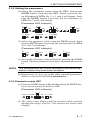
3.2.2 Setting the parameters
(1) Select the parameter name using the SEL. button and
MODE button. Each time the SEL. button is pressed, the
on/off pattern of LEDs No.3, 4, 5, and 6 will change. Each
time the MODE button is pressed, the on/off pattern of
LEDs No.7 and 8 will change.
[Parameter LED Indicator]
5
6
4
3 SEL.
8 7 MODE
5
6
4
3 SEL.
8 7 MODE
5
6
4
3 SEL.
5
6
4
3 SEL.
8 7 MODE
(2) Select the parameter value using the DATA button. Each
time the DATA button is pressed, the on/off pattern of LEDs
No.1 and 2 will change.
[Parameter LED Indicator]
2 1 DATA
2 1 DATA
2 1 DATA
2 1 DATA
(3) Accept the parameter value selected by pressing the LOAD
button. The next parameter for setup is automatically moved
to.
NOTE
The modifications will not be reflected in the actual operation unless they have been accepted.
(4) Repeat steps (1) to (3) to set the other required parameters.
(Refer to section 3.2.4 List of parameters.)
3.2.3 Parameter mode OFF
(1) Press the LOAD button while holding down the DATA button to set the parameter mode to OFF.
[Parameter LED Indicator]
5
LOAD 8 7 MODE 6
4
3 SEL. 2 1 DATA
(2) The count value display will be restored. (after passing
through the origin, only EV-16Z restores the count value
display)
No. 99MBC034B
3-7
NOTE
• If the LOAD button is held down for more than 1 second while the MODE button is held down, all parameters will be reset to the factory-set defaults.
• During the parameter setup operation, the D-EV keys,
RS-232C output, and external signal input are disabled.
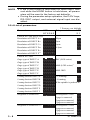
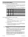
3.2.4 List of parameters
Parameter name
* Factory-set default
LED
Setup content
LED
876543
21
Case of EV-16P or EV-16Z
Resolution of INPUT A*1
10µm
Resolution of INPUT B*1
5µm
Resolution of INPUT C*1
1µm*
Resolution of INPUT D*1
0.5µm
Resolution of INPUT E*1
Resolution of INPUT F*1
Case of EV-16D
Gage type of INPUT A
INC (LGS series)
Gage type of INPUT B
Gage type of INPUT C
ABS (LGD series)*
Gage type of INPUT D
Gage type of INPUT E
ABS ORG
Gage type of INPUT F
Counting direction of INPUT A
+ Counting*
Counting direction of INPUT B
- Counting
Counting direction of INPUT C
If the spindle is pushed-in
Counting direction of INPUT D
Counting direction of INPUT E
Counting direction of INPUT F
Designation of available axis 1*2
Axis designation 2 is valid*
1 gage is connected
2 gages are connected
3 gages are connected
Designation of available axis 2*2
Axis designation 1 is valid*
4 gages are connected
5 gages are connected
6 gages are connected*
3-8
No. 99MBC034B
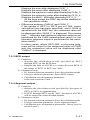
3 SETTING PARAMETERS
Parameter name
Start-up mode
* Factory-set default
LED
Setup content
LED
876543
21
Counting stand-by
Counting execution
Display unit*1*3
mm*
E (=1/25.4 mm)
Designation of calculation axis*4
CEL1, 2*
CEL1, 2, 3
CEL1, 2, 3, 4
All CELs*5
I/O output
mode*6
Command
Interval *
I/O output
logic*7
Output terminal is H*
Output terminal is L
Selection of I/O function*6
NORMAL mode*
Calculation mode
High-speed mode
Selection of I/O type*6
Tolerance judgment output*
Segment output
BCD output
Baud rate*8, *9
4800 bps
9600 bps*
19200 bps
Parity *8, *9
None
Odd number
Even number*
Data bits*8, *9
7 bits*
8 bits
HOLD
selection*9
HOLD*
RS-232C output *10
No. 99MBC034B
3-9
*1: If this parameter is modified, each zero point, preset value,
and tolerance value for CEL1 to CEL6 will all be cleared.
*2: For information about this function refer to TIP below.
*3: This is not modified even if an attempt is made to clear the
parameters. If the display unit is set to E, the UNIT LED
lights in green.
*4: Sets the CEL to be used for the calculation function. (This
function is valid only if Selection of I/O function is set to
Calculation mode.)
*5: If all CELs designated as the available axis are selected, CELs to be used for calculation will be as shown in
the table below.
Setup value for designating CEL to be used for calculation
the available axes
6
1, 2, 3, 4, 5, 6
5
1, 2, 3, 4, 5
4
1, 2, 3, 4
3
1, 2, 3
2 or 1
1, 2
*6: For information about this function refer to chapter 7 I/O
FUNCTION.
*7: The output logic of the data section will vary depending on
the I/O type selection result. However, each logic of the
input signal, NORMAL, READY, START, and EXTEND
output remains fixed.
Tolerance judgment and segment output
BCD output
The corresponding output terminal is
L, and others are H.
1=H, 0=L
The corresponding output terminal is
H, and others are L.
1=L, 0=H
*8: For information about this function refer to chapter 5 RS232C COMMUNICATION FUNCTION.
*9: The parameter modification will be made valid after resetting the power.
*10: This function will output data from the RS-232C connector
if a HOLD signal is input through the I/O connector.
In the case of "
", all RS-232C commands will be ineffective.
3 - 10
No. 99MBC034B
4
BASIC OPERATION
This chapter describes the basic operation of
the EV Counter with a D-EV.
4.1 Power ON Precautions
Turn on the power to the EV Counter by referring to section
2.3 Power On.
Neither move the gage stylus nor operate any key until the EV
Counter enters the counting stand-by state.
[Counting stand-by state (on D-EV)]
UNIT
+NG
GO
-NG
No. 99MBC034B
4-1
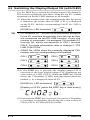
4.2 Switching the Display/Output CH (with D-EV)
Use the DISP key to switch the display/output CH (channel).
This section explains the procedure, using the top EV Counter
connected via the RS LINK function as an example.
(1) When the counter enters the counting mode after the power
is turned on, the count value of CH01 (CEL1) is displayed
on the D-EV, and the corresponding GAGE No. LED is
turned on.
GAGE
[GAGE No. LED Indicator]
TIP
• CH numbers (01 - 99) will be automatically assigned
to the EV counters sequentially from the top as they
are connected via the RS LINK function. If only one
counter is connected, it is assigned CH numbers 01
through 06, which corresponds to CEL1 through
CEL6. For more information refer to chapter 5, "RS
LINK FUNCTION".
• GAGE No. LEDs show the currently displayed CEL
number with the corresponding on/off pattern.
CEL1
CEL3
CEL5
GAGE
GAGE
GAGE
GAGE
CEL2
GAGE
CEL4
GAGE
CEL6
(2) If the DISP key is pressed, the display/output CH is
switched to the next display/output CH, displaying the
count value of CH02 (CEL2). While the DISP key is held
down, the CH number (CH02) and gage input connector
number (= b) is displayed on the D-EV.
GAGE
[GAGE No. LED Indication]
[Display on D-EV (while the DISP key is held down)]
UNIT
+NG
GO
-NG
(3) Each time the DISP key is pressed, the current CH number
is switched, sequentially displaying the count values of
CH03 (CEL3) to CH06 (CEL6) in order.
4-2
No. 99MBC034B
4 BASIC OPERATION
(4) If the DISP key is pressed again, a 6-axis tolerance judgment bar is displayed on the D-EV, showing all the judgment results from CEL1 to CEL6 at the same time.
GAGE
[Indication of GAGE No. LED]
[Display on D-EV]
CEL6 CEL5
UNIT
CEL4
CEL3
CEL2 CEL1
+NG
GO
-NG
NOTE
• While the bar is being displayed, only the DISP key
can be operated.
• The +NG and -NG bars are turned on for a CEL that
causes an error.
(5) If the DISP key is pressed again, the display of CH01
(CEL1) restores.
No. 99MBC034B
4-3
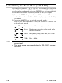
4.3 Switching the Peak Mode (with D-EV)
The internal counters, CEL1 - CEL6, will hold (lock) the peak
values (Max., Min., and TIR) of the count values. Therefore, by
switching the peak mode with the MODE key, it is possible to
switch the value to be displayed (on the D-EV) or output.
(1) Press the DISP key to select a CEL number. The count
value of the selected CEL will be displayed (on the D-EV)
or output.
(2) Press the MODE key to switch the peak mode.
The on/off pattern of the LEDs (on the D-EV) shows the
selected peak mode.
MAX
MAX
MAX
MAX
NOTE
4-4
TIR
TIR
TIR
TIR
MIN
Current value: Current stylus position
MIN
Max.: Maximum value since the peak value
was last cleared.
MIN
Min.: Minimum value since the peak value
was last cleared.
MIN
TIR: Max. - Min.
• Peak values are retained in memory even when the
power is off.
• The peak mode can be switched by RS-232C communication.
No. 99MBC034B
4 BASIC OPERATION
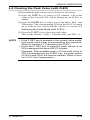
4.4 Clearing the Peak Value (with D-EV)
Held (retained) peak values can be cleared as necessary.
(1) Press the DISP key to select a CEL number. The count
value of the selected CEL will be displayed (on D-EV) or
output.
(2) Press the MODE key to select one of the Max., Min., and
TIR modes. The corresponding LED on the D-EV is turned
on to indicate the selected mode. (Refer to section 4.3
Switching the Peak Mode (with D-EV).)
(3) Press the P.SET key to clear the peak value.
This results in Max. = Min. = Current value, and TIR = 0.
NOTE
• If the P.SET key is pressed in the current-value mode,
both peak-value clear and presetting are executed.
(Refer to section 4.7 Presetting (with D-EV).
• Press the P.SET key to clear the peak values of all
CELs assigned the same INPUT number.
(Example: With available axes = 2 if the peak value of
CEL1 is cleared with the P.SET key, the peak values
of CEL3 and CEL5 will also be cleared. Refer to section 3.2.4 List of parameters.)
No. 99MBC034B
4-5
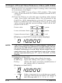
4.5 Input of Preset Value/Tolerance Value (with D-EV)
With the D-EV it is possible to input a setting value consisting
of a maximum of six digits.
(1) Press the DISP key to select a CEL number. The count
value of the selected CEL will be displayed (on the D-EV)
or output.
(2) Press the Fn key to select the type of setting value (preset
value, lower limit, and upper limit). The on pattern of the
GAGE No. LED, indicating the selected CEL number, will
flash in a different color according to the type of setting
value selected, and the current setting value will be displayed on the D-EV.
GAGE
Preset value
Lower tolerance limit
Upper tolerance limit
green
GAGE
amber
GAGE
red
[Display on the D-EV (current value display)]
UNIT
+NG
GO
-NG
NOTE
The D-EV Counter uses a 6-digit display, however a
value consisting of a maximum of eight digits can be
set using the RS-232C communication function. If a
number consisting of more than seven digits has already been set, the most significant one or two digits
will be represented by an "F", as in F34.567, on the
display.
(3) Enter the setting value.
MODE key: Shifts the digit place (flash) for input.
P.SET key: Inputs the setting value (places a digit).
Fn key:
Aborts the input operation (modification of
the setting value is canceled).
[Display on the D-EV]
UNIT
+NG
GO
-NG
UNIT
4-6
Either ± sign must be set with the most significant digit. The displayed number will change in
the following order: 0, 1, ...9, -0, -1, ...-9, 0.
No. 99MBC034B
4 BASIC OPERATION
(4) Repeat step 3 as required to place all digits, including the
least significant digit.
[Display on the D-EV]
UNIT
+NG
GO
-NG
NOTE
• If the gage resolution has been set to 5µm/0.5µm, set
the least significant digit to 0 or 5.
• Only one set of tolerance values can be set for each
CEL.
(5) While the least significant digit is flashing, press the MODE
key. The entered value is accepted and the flashing stops.
[Display on the D-EV]
UNIT
+NG
GO
-NG
(6) Press the Fn key to move to the next setup item.
The selected item will change as follows: preset value,
lower limit value, upper limit value, count value.
NOTE
• Preset values and tolerance values are retained in
memory even when the power is off.
• Set a lower tolerance limit that is equal to or smaller
than the upper tolerance limit. An incorrect setting
may cause a tolerance setting error (Err90). If this occurs, press the P.SET key and perform the input operation again, starting with the lower tolerance limit.
• In the case of using the EV-16D, perform presetting/
tolerance limit setting with the linear gage connected,
as the connected linear gage sets the resolution automatically
TIP
• If the RS-232C communication function is used, a preset value/tolerance value of a maximum of eight digits
can be set.
• The factory-set default preset value, lower limit value,
and upper limit value are as follows:
If a 1µm gage is used:00000.000 / -99999.999 /
99999.999
Display on D-EV:
000.000/ -F99.999/ F99.999
No. 99MBC034B
4-7
4.6 Clearing the Error State
The error state can be cleared with the following procedures.
If the EV-16Z is used, push in the spindle to pass through the
origin after completing the following procedures.
(1) Press the DISP key to select a CEL number in the error
state. Then press P.SET key.
(2) The HOLD input signal rises to "H". (I/O)
(3) Input the CS command. (RS-232C)
NOTE
• While the error state is being canceled, Error40 is displayed (on D-EV) or output.
• While the error state is being canceled, the GAGE No.
LED flashes.
• Time required for error cancelation: 30ms (EV-16P
and EV-16Z), max. 8s ( EV-16D)
4-8
No. 99MBC034B
4 BASIC OPERATION
4.7 Presetting (with the D-EV)
Replace the current value with a preset value.
(1) Press the DISP key to select a CEL number. The count
value of the selected CEL will be displayed (on the D-EV)
or output.
(2) Press the MODE key to select the current-value mode.
The on/off pattern of the LEDs show the selected mode.
[MODE LED Indicators]
MAX
TIR
MIN
(3) Press the P.SET key to replace the current value (displayed
value) with a preset value. At this time the peak values will
be cleared and Max. = Min. = Current value, and TIR = 0.
NOTE
• The EV Counter can count a maximum of eight digits,
however the D-EV Counter can display a maximum of
six digits. If a number has more than six digits, the
most significant one or two digits will be represented
by an "F". If the count value returns to a number of six
digits or less, the D-EV also returns to normal display.
Example)
Count value of EV Counter main unit:
Display on the D-EV:
1000.001
F00.001
• If the EV-16D is connected to an ABS_ORG type
gage, approximately four seconds is required for the
preset value to be recalled on the EV-16D. During this
time do not move the spindle. Doing so may displace
the zero point.
• An ABS or ABS_ORG type gage can be preset one
million times (nominal).
No. 99MBC034B
4-9
4.8 Tolerance Judgment (with the D-EV)
Three tolerance judgment result stages can be displayed on the
GAGE No. LEDs and output through the I/O connector. (For
more information about the I/O output function refer to chapter
7 I/O FUNCTION.)
(1) Press the DISP key to select a CEL number. The count
value of the selected CEL will be displayed (on the D-EV)
or output.
(2) Press the MODE key to select one of the peak modes: Max.,
Min., and TIR. The GAGE No. LED's on pattern, indicating
the selected CEL number will light in a different color according to the tolerance judgment result.
(Display example of tolerance judgment result from CEL1)
+NG:
GAGE
Red
(upper tolerance limit < design value)
GO:
GAGE
Green
(lower tolerance limit ≤ design value ≤ upper
tolerance limit)
-NG:
GAGE
Amber
(design value < lower tolerance limit)
NOTE
4 - 10
• There will always be six I/O output channels.
• The tolerance judgment result can be also verified
with the 6-axis tolerance judgment bar display. (Refer
to section 4.2 Switching the Display/Output CH (with
the D-EV).
No. 99MBC034B
5
RS-232C COMMUNICATION
FUNCTION
This chapter describes the RS-232C communication function.
5.1 RS-232C Connection
Connect the specified cable (D-sub, 9-pin cross-type cable) to
the RS-232C connector. The user must separately purchase this
cable.
NOTE
If multiple EV Counters are connected via the RS LINK
function, connect the above-mentioned cable to the RS232C connector of the first EV Counter.
5.2 RS-232C Output Specifications
5.2.1 Specifications of cables and connectors
Receptacle specification:
D-sub, 9-pin (male) inch-screw specification
Applicable plug specification:
D-sub, 9-pin (female) inch-screw specification
Examples of commercially available cables:
DOS/V: KRS-403XF 1K (1.5m, Manufacturer: Sanwa Supply)
PC-98: KRS-423XF 1K (1.5m, Manufacturer: Sanwa Supply)
5.2.2 Communication specifications (Conforms to EIA: RS232C standard)
Home position
Communication method
Data transfer rate
Bit configuration
Communication
condition settings
No. 99MBC034B
DTE (terminal), with cross-type cable
Half-duplex, teletype protocol
4800, 9600, 19200bps
Start bit: 1 bit
Data bits: 7 or 8-bit ASCII
uppercase characters
Parity bit: None, Even number,
Odd number
Stop bit: 2 bits
To be set with parameters
Refer to chapter 3 SETTING
PARAMETERS.
5-1
5.2.3 Pin assignment
Pin No. Signal name
1
NC
2
RXD
3
TXD
4
DTR
5
GND
6
DSR
7
RTS
8
CTS
9
NC
1
I/O
---I
O
O
---I
O
I
----
Description
Not connected
Received Data
Transmission Data
Data Terminal Ready
Ground
Data Set Ready
Request to Send
Clear to Send
Not connected
RS-232C
5
6
9
5.2.4 List of available commands
Command format
GA**CRLF
CN**CRLF
CX**CRLF
CM**CRLF
CW**CRLF
CR**CRLF
CL**CRLF
CP**,
+01234.567CRLF
CD**,
+01234.567CRLF
CG**
+01234.567CRLF
CS** CRLF
CK** CRLF
CT\\CRLF
Corresponding
output
G#**
+01234.567CRLF
CH**CRLF
CH**CRLF
CH**CRLF
CH**CRLF
CH**CRLF
CH**CRLF
CH**CRLF
Operation
CH**CRLF
Inputs lower tolerance limit*2,*3
CH**CRLF
Inputs upper tolerance limit*2,*3
Outputs the displayed value.*1
Switches to the current value display
Switches to the max. value display
Switches to the min. value display
Switches to the TIR display
Zero-sets.
Clears peak values
Presets.*2
CH**CRLF
Clears the error.
CH**, %CRLF Returns the HOLD status*4,*6
CH\\,
Outputs the calculation data*5,*6,*7
+01234,567CRLF
*1: A "#" denotes the data type (N: Current value, X: Maximum, M: Minimum, W: TIR).
*2: For a preset value or tolerance value input a number that
consists of a maximum of eight digits (not including a decimal point) and its sign.
5-2
No. 99MBC034B
5 RS-232C COMMUNICATION FUNCTION
*3: For the tolerance setting, first enter the lower limit value,
then the upper limit value.
An error will result if the entries are not made in this order.
If this is the case, make the setting again, starting with the
CD command entry.
*4: The response output value (%) for the entered CK command
represents the HOLD status.
% = 1: The counter is in the HOLD state.
% = 0: The counter is not in the HOLD state.
*5: Precautions to be observed when calculation data is output
by the CT command:
This command is valid only if the I/O function selection parameter is set to "Calculation mode".
A double backslash (\\) is used to specify the calculation
method between the axes which have been specified by the
calculation axis designation parameter.
Value of double
backslash
01, 07*, 12**
02, 08*, 13**
03, 09*, 14**
04, 10*, 15**
05, 11*, 16**
Operation
Obtains each total of specified axes.
Obtains each mean of specified axes.
Obtains the max. value of specified axes.
Obtains the min. value of specified axes.
Obtains Max. - Min. of specified axes.
If more than one EV Counter unit is connected via the RSLINK function:
*: Value of double backslash on the second counter.
**: Value of double backslash on the third counter.
*6: An all-channels specification is not permitted with the CK
or CT command. If all channels are specified, a command
error results.
*7: The CT command cannot be used with the EF Counter.
NOTE
• A double asterisk (**) denotes a channel number between 01 and 99 (00 means all channels).
• CRLF means a CR (carriage return) and an LF (line
feed).
• The output when an error occurs will be "CH ** ,
Error$$CRLF".
("$$" denotes the error code number. Refer to section
8.4 List of Error Outputs.)
• Send the next command only after the response output to the current command has been received. If no
response to the current command has been received,
clear the buffer and wait for more than one second,
then send the same command again.
No. 99MBC034B
5-3
• The RS-232C communication function is suspended
during a parameter, preset value, or tolerance value
setup operation. If the counting state is restored, output of the command or data will be resumed.
• To quit the counting stand-by state use "CS00CRLF"
(all-channels specification).
• Note that the GA command and CT command look
similar, however, their functions differ.
GA command: Outputs the count data of a CH
specified by "##".
CT command: Outputs the calculation result
specified by a double backslash.
• If the peak mode is switched using an RS-232C command, peak values cannot be backed up in memory.
5-4
No. 99MBC034B
5 RS-232C COMMUNICATION FUNCTION
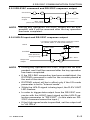
5.2.5 RS-232C command and RS-232C response output
Command
LF
LF
Response
output
LF
Max. 10ms
(If the GA command is issued)
NOTE
Min. 10ms
During key operation RS-232C output will be suspended, and it will be resumed after the key operation
has been completed.
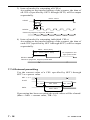
5.2.6 HOLD input and RS-232C response output
* A value in brackets denotes a numeric value
at a MAX, MIN, or TIR measurement.
HOLD
Min. 10ms
Max. 70ms
EXTEND
Data latch for
10 µs [10 ms]*
Response
output
NOTE
Min. 10ms
LF
• During key operation RS-232C output will be suspended, and it will be resumed after the key operation
has been completed.
• If the RS LINK connection has been established, the
EXTEND command is valid for the counter placed at
the end of the chain.
• EXTEND output will be in effect only if the I/O mode
parameter is set to "Interval mode".
• While the HOLD signal is being input, the D-EV UNIT
LED flashes.
• In order to trigger data output from the RS-232C connector with the HOLD input signal set the HOLD selection parameter to "RS-232C". (In this state an RS232C command cannot be input.)
• If the High-speed mode is specified, set the output cell
to "All CELs".
No. 99MBC034B
5-5
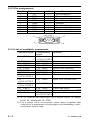
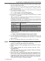
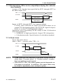
5.2.7 Time required for RS-232C data output
The maximum output time (ms) as a result of executing the alldata output command (GA00CRLF) is calculated as follows:
= (number of connected counters x 10) + (number of available
channels x 17) + 6
[= (number of connected counters x 10) + (number of available
channels x 8.5) + 3]
Transmission speed: 9600bps [19200bps]
(Example)
One EV-16P unit (total 6 gage channels): Max. 118ms [64ms]
Ten EV-16P units (total 60 gage channels): Max. 1126ms [610ms]
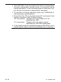
NOTE
• "Number of connected counters x 20" is used for EF
Counters.
• The above figures do not include personal computer
processing time.
• The data size required if total 60 gage channels are
used, is 900 bytes (15 bytes per gage channel). For
more information refer to the specifications of the reception-side personal computer.
5-6
No. 99MBC034B
6
RS LINK FUNCTION
This chapter describes the RS LINK function
that controls multiple counters connected via
dedicated cables.
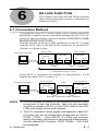
6.1 Connection Method
A maximum of ten EV Counter units can be chain-connected,
and all the counters can be controlled through the RS-232C interface of the top counter. (Refer to chapter 5 RS-232C COMMUNICATION FUNCTION.)
Link the IN side of the RS LINK connector of one EV Counter
with the OUT side of the RS LINK connector of another EV
Counter, as shown below.
Personal computer
Top counter
RS LINK
RS-232C
IN
OUT
End counter
RS LINK
IN
OUT
RS LINK
IN
OUT
10 units
maximum
RS LINK connection cable with
a maximum length of 10 m
If one D-EV is inserted in the middle, as shown below, it will
display the data of EV Counter: A.
Personal computer
EV Counter: A
RS LINK
RS-232C
IN
OUT
D-EV
RS LINK
IN
OUT
EV Counter: B
RS LINK
IN
OUT
RS LINK connection cable (optional)
NOTE
• Do not connect anything to the IN side of the RS LINK
connector of the top counter. Also, do not connect
anything except a D-EV to the OUT side of the RS
LINK connector of the end counter.
• The CH numbers of the gages connected to each EV
Counter will be automatically assigned as CH01,
CH02, CH03..., from INPUT A of the top counter
when the power is turned on (during the initial setup).
On the second EV Counter, CH07, CH08,....CH12 will
be assigned.
No. 99MBC034B
6-1
• One or more EF Counters can be combined with the
EV Counters. However, if this is done, a maximum of
six EF Counters can be combined. A D-EV, if inserted, will not be included in the number of connected units.
• The maximum total length of the RS LINK cables
used in the entire system is 10m.
• Consult Mitutoyo to construct a system with more
than 10 counters and/or a total cable length greater
than 10m.
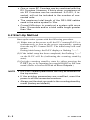
6.2 Start-Up Method
Start up the entire system with the following procedure.
(1) Either turn on the power to all the EV Counters/D-EVs simultaneously or turn on the power sequentially, starting
from the top EV Counter/D-EV. The initial setup will commence.
During initial setup, the D-EV displays a flashing "-----".
(2) If the initial setup has been completed, the flashing "-----"
on the D-EV will fix (indicating the counting stand-by
state).
(3) Quit the counting stand-by state by either pressing the
P.SET key or by inputting an external HOLD or RS command. (Refer to section 8.4 List of Error Outputs.)
NOTE
• RS-232C-related parameters can only be modified on
the top counter.
• If the existing parameters are modified, reset the
power to all the connected counters.
• Always set the start-up mode to the counting stand-by
mode (factory-set default).
6-2
No. 99MBC034B
6 RS LINK FUNCTION
6.3 Troubleshooting
If communication with the personal computer is not functioning
well, refer to the following examples:
• If no response to the entered command is received from the
EV Counter.
1) Is the RS LINK cable connected properly?
2) Is a straight-type RS-232C cable used?
3) Are the personal computer and EV Counter communication conditions consistent?
4) With some computers it is necessary to specify the communication port and whether it is to be used. Is a cable
properly connected to the specified port?
5) Is key operation or parameter setup operation being performed?
(During the above-mentioned operations, RS-232C communication function is paused/suspended.)
• The initial setup operation cannot be terminated ("-----"
flashes on the D-EV).
• Some counter enter the counting stand-by state ("-----" is
displayed on the D-EV) while the power is being turned on.
1) Is the RS LINK cable connected properly?
2) If EF Counters are being used with EV Counters, make
sure that the Digimatic selection parameter of the EF
Counter is set to "RS LINK".
After removing the cause of the error, reset the power
to all counters.
• A command (such as a zero-set or preset command) from
the personal computer can be executed, but no data can be
acquired. Or, data processing is stopped during data acquisition.
1) Is the response output from the counter read with such as
the zero-set command, etc?
2) Is the next command issued before the response output
from the counter is received?
3) Is the number of channels connected via the RS LINK
function consistent with the number of data pieces to be
acquired?
• A command abnomaly occurs if a command is issued.
1) Was a command consisting of 2-byte characters or lowercase characters issued?
2) Don't you specify a number greater than the number of
channels connected?
No. 99MBC034B
6-3
6-4
No. 99MBC034B
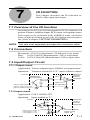
7
I/O FUNCTION
This chapter describes the I/O function related to data input and output.
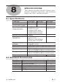
7.1 Overview of the I/O function
According to the I/O-type selection parameter, the I/O connector will
perform tolerance judgment output, BCD output, and segment output.
Each output can be performed in the NORMAL mode, calculation
mode, or high-speed mode as set by the I/O function selection parameter. (Refer to chapter 3 SETTING PARAMETERS.)
NOTE
The user must separately purchase the connection cable.
7.2 Connectors
Receptacle: 10236-52A2 (Manufacturer: 3M, half-pitch 36-pin, female)
Plug: 10136-3000VE (Manufacturer: 3M) or equivalent
Cover: 10336-52A0-008 (Manufacturer: 3M) or equivalent
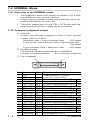
7.3 Input/Output Circuit
7.3.1 Output circuit
Application: Tolerance judgment output, NORMAL, and segment output
Operation: Transistor turned ON at "L" (open-collector output)
Counter
+5V
TD62853 or
the equivalent
5kΩ
Output
Reference
circuit of
external
equipment
0.01uF
COM
Maximum output voltage: 24 V
Maximum output current: 10 mA
Maximum saturation voltage: 0.7 V
74HC14 or
the equivalent
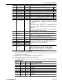
7.3.2 Input circuit
Application: P.SET, HOLD, SET
Operation: Input enabled at "L"
Counter
+5V
5kΩ
Maximum input current: 1 mA 0.01uF
Input voltage (H): 4 - 24 V
Input voltage (L): 1 V max.
No. 99MBC034B
Input
COM
Reference
circuit of
external
equipment
Use open-collector
output or relay
output, etc.
7-1
7.4 NORMAL Mode
7.4.1 Overview of the NORMAL mode
• The NORMAL mode is the factory-set default. Use it without modification for general purposes.
• Origin setting, tolerance setting, and presetting can be performed individually for each CEL.
• Tolerance judgment (for each CEL), BCD data, and segment (on selected CELs) output can be performed.
7.4.2 Tolerance judgment output
1) Function
Outputs the tolerance judgment result of each internal
counter (CEL1 to CEL6).
Measured value < Lower tolerance limit
-NG output
Lower tolerance limit ≤ Measured value ≤ Upper tolerance limit
GO output
Upper tolerance limit < Measured value
+NG output
2) Parameter setup
I/O function selection parameter: Set to NORMAL
I/O-type selection parameter:
Set to tolerance judgment
3) Pin assignment
No.
1
2
3
4
5
6
7
8
9
10
11
12
13
14
15
16
17
18
7-2
Name
COM
COM
CEL1_-NG
CEL1_GO
CEL1_+NG
CEL1_NOM
CEL2_-NG
CEL2_GO
CEL2_+NG
CEL2_NOM
CEL3_-NG
CEL3_GO
CEL3_+NG
CEL3_NOM
CEL4_-NG
CEL4_GO
CEL4_+NG
CEL4_NOM
18
1
36
19
I/O
OUT
OUT
OUT
OUT
OUT
OUT
OUT
OUT
OUT
OUT
OUT
OUT
OUT
OUT
OUT
OUT
Functional description
Common terminal of I/O circuit
(connected to internal GND)
Tolerance judgment result of CEL1
Tolerance judgment result of CEL1
Tolerance judgment result of CEL1
Error signal of CEL1*1
Tolerance judgment result of CEL2
Tolerance judgment result of CEL2
Tolerance judgment result of CEL2
Error signal of CEL2*1
Tolerance judgment result of CEL3
Tolerance judgment result of CEL3
Tolerance judgment result of CEL3
Error signal of CEL3*1
Tolerance judgment result of CEL4
Tolerance judgment result of CEL4
Tolerance judgment result of CEL4
Error signal of CEL4*1
-NG
GO
+NG
-NG
GO
+NG
-NG
GO
+NG
-NG
GO
+NG
No. 99MBC034B
7 I/O FUNCTION
No.
19
20
21
22
23
24
25
26
27
Name
CEL5_-NG
CEL5_GO
CEL5_+NG
CEL5_NOM
CEL6_-NG
CEL6_GO
CEL6_+NG
CEL6_NOM
EXTENDED
I/O
OUT
OUT
OUT
OUT
OUT
OUT
OUT
OUT
OUT
28
29
30
READY
START
NORMAL
OUT
OUT
OUT
31
32
33
34
35
36
P.SET
OUTCEL
SET1
SET2
SET3
HOLD
IN
IN
IN
IN
IN
IN
Functional description
Tolerance judgment result of CEL5
-NG
Tolerance judgment result of CEL5
GO
Tolerance judgment result of CEL5
+NG
Error signal of CEL5*1
Tolerance judgment result of CEL6
-NG
Tolerance judgment result of CEL6
GO
Tolerance judgment result of CEL6
+NG
Error signal of CEL6*1
L: Execution of an RS-232C command, which
is activated by a HOLD input, is being
performed.
H: Execution of an RS-232C command, which
was activated by a HOLD input, has been completed.
Purpose: Monitoring the RS data communication condition at the I/O port.
"L" if the output data has been accepted.
"L" only when CEL1 data has been output.
"H" at an anomaly.
(Result of ORing NOMs of all CELs.)
Presets the specified CELs.
Sets the output CEL/calculation method
specified by SET1 through SET3 if the ON
signal of OUTCEL was input.
The display value is held during input. The
error is cleared at the rise of this signal.
Only EV-16Z re-detects the origin if the
parameter No.42 is set to 1.
*1: "L" if counting is permitted.
*: Outputs of No.3 through No.26 can be logically inverted by the I/O
output logic parameter.
**: Inputs of No.31 through No.36 are valid at "L".
4) Designating the CEL for "P.SET"
For the detailed procedure, refer to section 7.7.4 External
presetting.
SET3 SET2 SET1 CEL specified
0
0
0
All CELs
0
0
1
CEL1
0
1
0
CEL2
0
1
1
CEL3
1
0
0
CEL4
1
0
1
CEL5
1
1
0
CEL6
1
1
1
Specification prohibited.
0="H" 1="L"
No. 99MBC034B
7-3
7.4.3 BCD output
1) Function
Outputs the CEL data specified by the output CEL designation as a BCD (6 digits).
2) Parameter setup
I/O function selection parameter: Set to NORMAL
I/O-type selection parameter:
Set to BCD output
3) Pin assignment
No.
1
2
3
4
5
6
7
8
9
10
11
12
13
14
15
16
17
18
19
20
21
22
23
24
25
26
27
28
29
30
31
7-4
Name
COM
COM
1×100
2×100
4×100
8×100
1×101
2×101
4×101
8×101
1×10²
2×10²
4×10²
8×10²
1×10³
2×10³
4×10³
8×10³
1×10⁴
2×10⁴
4×10⁴
8×10⁴
1×10⁵
2×10⁵
4×10⁵
8×10⁵
SIGN
18
1
36
19
I/O
Functional description
Common terminal of I/O circuit
(connected to internal GND)
OUT BCD output data
OUT
OUT
OUT
OUT
OUT
OUT
OUT
OUT
OUT
OUT
OUT
OUT
OUT
OUT
OUT
OUT
OUT
OUT
OUT
OUT
OUT
OUT
OUT
OUT Sign of count value
("H" for "+" and "L" for "-")
READY OUT "L" if the output data has been accepted.
START OUT "L" if only CEL1 data has been output.
NORMAL OUT "H" at an anomaly
P.SET
IN
Presets the specified CELs.
No. 99MBC034B
7 I/O FUNCTION
No.
32
33
34
35
Name
OUTCEL
SET1
SET2
SET3
I/O
IN
IN
IN
IN
36
HOLD
IN
Functional description
Sets the output CEL/calculation
method specified by SET1 through SET3
if the ON signal of OUTCEL was input.
In NORMAL/High-speed mode:
CEL designation
In calculation mode:
Specification of calculation method
The display value is held during the input.
The error is cleared at the rise of this signal.
Only EV-16Z re-detects the origin if the parameter No.42 is set to 1.
*: Outputs of No.3 through No.27 can be logically inverted
by the I/O output logic parameter.
**: Inputs of No.31 through No.36 are valid at "L".
4) Designating CELs to be output
For the detailed procedure, refer to section 7.7.5 Designating CELs to be output/Specifying the calculation
method.
SET3 SET2 SET1 Operation
0
0
0
Outputs the data of all CELs as a
time-division BCD (power-on default)
0
0
1
BCD output of CEL1 data
0
1
0
BCD output of CEL2 data
0
1
1
BCD output of CEL3 data
1
0
0
BCD output of CEL4 data
1
0
1
BCD output of CEL5 data
1
1
0
BCD output of CEL6 data
1
1
1
Specification prohibited.
0="H" 1="L"
No. 99MBC034B
7-5
7.4.4 Segment output
1) Function
Outputs the CEL data specified by the output CEL designation as segment data.
The segment output function is used to evenly divide the
measurement range previously set into 21 segments, so that
the 21 tolerance judgment stages of the measured value can
be output.
21 pins numbered from -L10 to +L10 are used for this segment output.
2) Parameter setups
I/O function selection parameter: Set to NORMAL.
I/O-type selection parameter:
Set to segment output
3) Pin assignment
7-6
No.
1
2
3
Name
COM
COM
-OV
4
5
6
7
8
9
10
11
12
13
14
15
16
17
18
19
20
21
22
23
24
-L10
-L9
-L8
-L7
-L6
-L5
-L4
-L3
-L2
-L1
L0
+L1
+L2
+L3
+L4
+L5
+L6
+L7
+L8
+L9
+L10
18
1
36
19
I/O
Functional description
Common terminal of I/O circuit
(connected to internal GND).
OUT To be output if the measured value
exceeds the measurement range.
OUT Segment output data.
OUT
OUT
OUT
OUT
OUT
OUT
OUT
OUT
OUT
OUT
OUT
OUT
OUT
OUT
OUT
OUT
OUT
OUT
OUT
OUT
No. 99MBC034B
7 I/O FUNCTION
No. Name
25 +OV
I/O
OUT
26
27
NOM
EXTEND
OUT
OUT
28
29
30
31
32
33
34
35
READY
START
NORMAL
P.SET
OUTCEL
SET1
SET2
SET3
OUT
OUT
OUT
IN
IN
IN
IN
IN
36
HOLD
IN
Functional description
To be output if the measured value
exceeds the measurement range.
"H" at an anomaly
L: Execution of an RS-232C command,
which was activated by a HOLD input, is
being performed.
H: Execution of an RS-232C command,
which was activated by an HOLD input,
has been completed.
Purpose: Monitoring the RS data communication condition at the I/O port.
"L" if the output data has been accepted.
"L" if only CEL1 data has been output.
"H" at an anomaly
Presets the specified CELs.
Sets the output CEL/calculation
method specified by SET1 through SET3
if the ON signal of OUTCEL was input.
In the NORMAL/High-speed mode:
CEL designation.
In the calculation mode:
Specification of calculation method.
The display value is held during the input.
The error is cleared at the rise of this signal.
Only EV-16Z re-detects the origin if the parameter No.42 is set to 1.
*: Outputs of No.3 through No.26 can be logically inverted
by the I/O output logic parameter.
**: Inputs of No.31 through No.36 are valid at "L".
4) Designating CELs to be output
For the detailed procedure, refer to section 7.7.5 Designating
CELs to be output/Specifying the calculation method.
SET3 SET2 SET1 Operation
0
0
0
Outputs the data of all CELs as timedivision segment data (power-on
default)
0
0
1
Segment output of CEL1 data
0
1
0
Segment output of CEL2 data
0
1
1
Segment output of CEL3 data
1
0
0
Segment output of CEL4 data
1
0
1
Segment output of CEL5 data
1
1
0
Segment output of CEL6 data
1
1
1
Specification prohibited.
0="H" 1="L"
No. 99MBC034B
7-7
5) Measurement range: Can be specified/modified by inputting
SET1 through SET3 (For more information, refer to section
7.7.5 Designating CELs to be output/Specifying the
calculation method.)
List of measurement ranges: If the peak mode is set to current value, MAX, or MIN.
SET SET SET Measurement range (mm)/ Resolution (mm)
1 2 3
10µm gage 5µm gage 1µm gage 0.5µm gage
0
0
0
0±0.1
0±0.05
0±0.01
0±0.005
/0.01
/0.005
/0.001
/0.0005
0
0
1
0±0.2
0±0.1
0±0.02
0±0.01
/0.02
/0.01
/0.002
/0.001
0
1
0
0±0.5
0±0.25
0±0.05
0±0.025
/0.05
/0.025
/0.005
/0.0025
0
1
1
0±1
0±0.5
0±0.1
0±0.05
/0.1
/0.05
/0.01
/0.005
1
0
0
0±2
0±1
0±0.2
0±0.1
/0.2
/0.1
/0.02
/0.01
1
0
1
0±5
0±2.5
0±0.5
0±0.25
/0.5
/0.25
/0.05
/0.025
1
1
0
0±10/1
0±5/0.5
0±1/0.1
0±0.5/0.05
1
1
1
0±20/2
0±10/1
0±2/0.2
0±1/0.1
List of measurement ranges: If the peak mode is set to TIR.
SET SET SET Measurement range (mm)/ Resolution (mm)
1 2 3
10µm gage 5µm gage 1µm gage 0.5µm gage
0
0
0
0-0.2
0-0.1
0-0.02
0-0.01
/0.01
/0.005
/0.001
/0.0005
0
0
1
0-0.4
0-0.2
0-0.04
0-0.02
/0.02
/0.01
/0.002
/0.001
0
1
0
0-1.0
0-0.5
0-0.1
0-0.05
/0.05
/0.025
/0.005
/0.0025
0
1
1
0-2
0-1
0-0.2
0±0.1
/0.1
/0.05
/0.01
/0.005
1
0
0
0-4
0-2
0-0.4
0-0.2
/0.2
/0.1
/0.02
/0.01
1
0
1
0-10
0-5
0-1
0-0.5
/0.5
/0.25
/0.05
/0.025
1
1
0
0-20/1
0-10/0.5 0.1(0)-2/0.1 0-1/0.05
1
1
1
0-40/2
0-20/1
0-4/0.2
0-2/0.1
Each resolution (range of one segment) is a value derived
from the measurement range evenly divided by twenty.
Example: If the measurement range = 0.1mm, the resolution
= 0.01mm.
7-8
No. 99MBC034B
7 I/O FUNCTION
6) Relationship between the measurement value and output
terminal
If a segment output is designated, the output terminal (corresponding terminal Ln) corresponding to the measurement
value is turned ON.
'n' of corresponding terminal Ln (-10 ≤ n ≤ +10, n is an integer) can be calculated as follows. (If n is between -10 and -1,
the corresponding terminal will be between -L10 and -L1.)
Peak mode
Current value
MAX
MIN
TIR
Formula for n
If the measurement value is positive:
n = INT{(measurement value + 1/2 resolution)
/resolution}
If the measurement value is negative
n = INT{(measurement value - 1/2 resolution)
/resolution}
n = -10 + INT(measurement value/resolution)
7) Output pattern
The segment output pattern varies with the peak mode
setup.
Peak mode
Output
Current value Only the corresponding terminal, Ln, is ON.
MAX
Corresponding terminals from -L10 to Ln are ON.
MIN
Corresponding terminals from Ln to +L10 are ON.
TIR
Only the corresponding terminal, Ln, is ON.
NOTE
Output at range-over
Should a +0V (the measurement exceeds the upper
limit) or -0V (the measurement falls below the lower
limit) range-over occur, all terminals between -L10 to
+L10 will be set to OFF.
TIP
• Difference between CH01=A and CH01_A
A CEL that is represented so as to include "=" when
the display is switched with the DISP key, is output
with the I/O function. A CEL that is represented so as
to include "_" is not output by the I/O function.
• How to make general tolerance judgment
Before tolerance judgment output, set the I/O output
logic parameter to "Output terminal is H". This enables general tolerance judgment, in which the output
is "H" if all the CELs, which are connected in such a
way that the GO output of each CEL is connected by
means of hard-wire OR operation, result in GO.
No. 99MBC034B
7-9
7.5 Calculation Mode
7.5.1 Overview of the calculation mode
1) Using the CEL that has been specified by the calculation
axis designation parameter, output the calculation result
specified by the input of SET1 to SET3, as shown below.
2) Setting the calculation method
(For the detailed procedure, refer to section 7.7.5 Designating
CELs to be output/Specifying the calculation method .)
SET3
0
0
0
0
1
1
SET2
0
0
1
1
0
0
SET1
0
1
0
1
0
1
1
1
1
1
0
1
Calculation method
No calculation (power-on default)
Sum of CEL data on specified calculation axes
Mean of CEL data on specified calculation axes
Max. of CEL data on specified calculation axes
Min. of CEL data on specified calculation axes
MAX - MIN of CEL data on specified calculation
axes
Specification prohibited.
Specification prohibited.
0="H" 1="L"
7.5.2 Tolerance judgment result output
1) Function
• A tolerance judgment of the calculation result will be output from CEL6.
• In case of no calculation, a tolerance judgment to the
count value of CEL6 will be output.
• The tolerance limits for CEL6 will be applied.
2) Parameter setup
• I/O function selection parameter: Set to the calculation mode.
• I/O-type selection parameter: Set to tolerance judgment.
• Calculation axis designation parameter:
Select one between 0 and 3.
TIP
7 - 10
• Display on the D-EV when the calculation mode is being set.
If the display is switched with the DISP key, the following will be sequentially displayed after normal display
(CH01 to CH06 and 6-axis tolerance judgment bar):
Displays the sum after displaying CL01_1.
Displays the mean after displaying CL02_2.
Displays the maximum value after displaying CL03_3.
Displays the minimum value after displaying CL04_4.
Displays the MAX - MIN after displaying CL05_5.
For the second EV Counter on the RS LINK, the following will be displayed:
No. 99MBC034B
7 I/O FUNCTION
Displays the sum after displaying CL07_1.
Displays the mean after displaying CL08_2.
Displays the maximum value after displaying CL09_3.
Displays the minimum value after displaying CL10_4.
Displays the MAX - MIN after displaying CL11_5.
* All the keys except the DISP key will be disabled in
the calculation mode.
• Difference between CH06=F and CH06_F.
If the setups of SET1 to SET3 are not '000' (some
calculation item has been specified), and if CH06 is
specified with the DISP key, the measured value will
be displayed after 'CH06_F' is displayed. This means
that "_" indicates that tolerance judgment output is not
performed for the CH06 measurement value (i.e. the
tolerance judgment output is performed for the calculation result).
In other cases, where SET=000, a tolerance judgment will be output to the measured value of CH06
and the measured value will be displayed after
'CH06=F' is displayed.
7.5.3 BCD output
1) Function
• Outputs the calculation results specified by SET1
through SET3 as the BCD data.
• Outputs the data of all CELs as a time-division BCD, if
the setups of SET1 to SET3 are "000".
2) Parameter setup
• I/O function selection parameter: Set to the calculation mode.
• I/O-type selection parameter: Set to BCD output.
• Calculation axis designation parameter:
Select one between 0 and 3.
7.5.4 Segment output
1) Function
• Outputs the calculation result specified by the input of
SET1 to SET3 as segment data.
• If SET3 through SET1 are all "000", the data of all CELs
will be output in a time-divided format.
2) Parameter setups
• I/O function selection parameter: Set to the calculation mode.
• I/O type selection parameter: Set to segment output.
• Calculation axis designation parameter: Select one between 0 and 3.
No. 99MBC034B
7 - 11
7.6 High-speed Mode
7.6.1 Overview of the high-speed mode
1) Quickly outputs the CEL data specified by the output CEL
designation.
2) Data output interval in the high-speed mode
5ms (30ms in NORMAL mode)
3) Designating CELs to be output
For the detailed procedure, refer to section 7.7.5 Designating
CELs to be output/Specifying the calculation method.
SET3 SET2 SET1
0
0
0
0
0
1
0
1
0
0
1
1
1
0
0
1
0
1
1
1
0
1
1
1
0="H" 1="L"
Output CEL
Outputs the data of all CELs in a timedivision output format, as in the
NORMAL mode (power-on default).
High-speed output of CEL1 data*
High-speed output of CEL2 data*
High-speed output of CEL3 data*
High-speed output of CEL4 data*
High-speed output of CEL5 data*
High-speed output of CEL6 data*
Specification prohibited.
* Other CEL output functions are disabled.
NOTE
About operation during suspension
• Presetting, peak clear, or zero-setting operation (with
D-EV, I/O, RS-232C) for CELs other than those which
have been specified by SET1 through SET3 will be
suspended, and they become effective only after the
CEL has been specified.
• Even if the tolerance judgment bar display is active, only
the bars of CELs that have been specified will operate.
• RS-232C output from CELs other than those which have
been specified by SET1 through SET3 will be the previous data (existed when the suspension state began).
• If the CELs, excluding that which is displayed on the
D-EV, are specified for output CEL designation, the
display values will be held (locked).
• If key operation is attempted on the D-EV, the I/O function will output all CEL data in a time-division format.
7 - 12
No. 99MBC034B
7 I/O FUNCTION
7.6.2 Tolerance judgment result output
1) Function
A tolerance judgment of the CEL, which has been specified
by output CEL designation, will be output at high speed.
2) Parameter setups
• I/O function selection parameter: Set to the high-speed
mode.
• I/O-type selection parameter: Set to tolerance judgment
output.
7.6.3 BCD output
1) Function
Quickly outputs the CEL data specified by output CEL designation as BCD data.
2) Parameter setups
• I/O function selection parameter: Set to the high-speed
mode.
• I/O-type selection parameter: Set to BCD output.
7.6.4 Segment output
1) Function
Quickly outputs the CEL data specified by output CEL designation as segment data.
2) Parameter setups
• I/O function selection parameter: Set to the high-speed
mode.
• I/O-type selection parameter: Set to segment output .
No. 99MBC034B
7 - 13
7.7 Timing Chart
7.7.1 Power ON characteristics
Min. 2sec (Min. 3.5sec)
Power supply
( ): EV-16D
Min. 35ms
HOLD
Max. 35ms
NORMAL
Max. 2sec (Max. 3.5sec)
I/O output
If linked to RS-LINK, the counter that is turned on last will be
used as the reference.
7.7.2 Output period of tolerance judgment result
CEL outputs are not simultaneous.
Upper limit
Lower limit
Count data
-NG
+NG
NOTE
7 - 14
Max. 35ms (Max. 10ms)
[Max. 90ms]
( ): High-speed mode only
for specified CELs
(However, this is not
effective if an all-CEL
specification is made.)
[ ]: Calculation mode
Max. 35ms
(Max. 10ms)
[Max. 90ms]
With an EV-16D, the output period varies according to
the gage connected.
No. 99MBC034B
7 I/O FUNCTION
7.7.3 Data output
There are two data output methods that can be specified by the
I/O output mode parameter: the command mode and the interval mode.
1) Command mode (for outputting all CELs)
With synchronized control of the HOLD and READY signals, the data of all CELs (specified by SET1 through SET3)
will be output.
Min. 70ms
Min. 15ms
HOLD
START
Data latch for 10 µs (10 ms at a peak measurement), for EV-16P and EV-16Z.
Max. 40ms
5ms - 6ms
1.6ms - 2ms
READY
Tolerance judgment, segment, BCD data
CEL1
CEL2
CEL3
CEL4
CEL5
CEL6
* While the HOLD signal is being input, the UNIT LED (on DEV) will flash.
2) Command mode (for outputting individual CELs)
With synchronized control of the HOLD and READY signals, the data of each CEL (specified by SET1 through
SET3) will be output.
Min. 40ms (Min. 15ms) [Min. 70ms]
Min. 15ms
HOLD
Data latch for 10 _s (10 ms at a peak measurement), for EV-16P and EV-16Z.
Max. 40ms
(Max. 15ms)
[Max. 80ms]
12ms - 15ms
(1.6ms - 2ms)
( ): If outputted in the
high-speed mode.
[ ]: If outputted in the
calculation mode.
READY
Tolerance judgment, segment, BCD data
NOTE
If this command is used in the high-speed mode or in the
all-CELs output mode, use a device that has an input
response time that is less than 1ms.
No. 99MBC034B
7 - 15
3) Interval mode (for outputting all CELs)
According to the internal timing of the counter, the data of
all CELs (specified by SET1 through SET3) will be output
sequentially.
30ms - 35ms
START
5ms - 6ms
1.6ms - 2ms
READY
Tolerance judgment, segment, BCD data
CEL1
CEL2
CEL3
CEL4
CEL5
CEL6
4) Interval mode (for outputting individual CELs)
According to the internal timing of the counter, the data of
each CEL (specified by SET1 through SET3) will be output
sequentially.
30ms - 35ms (5ms)
12ms - 15ms (1.6ms - 2ms)
( ): If outputted in the
high-speed mode
READY
Tolerance judgment, segment, BCD data
7.7.4 External presetting
Use the current value of a CEL specified by SET1 through
SET3 as a preset value.
SET 1, 2, 3
P. SET
Min. 10ms
DATA
Min. 10ms
Min. 15ms
Max. 40ms
If presetting has been executed, the peak values will be cleared.
(Max.= Min. = current value, TIR = 0)
7 - 16
No. 99MBC034B
7 I/O FUNCTION
7.7.5 Designating CELs to be output/Specifying the calculation method
Assign a CEL that has been specified by SET1 through SET3 as
the data output CEL.
SET 1, 2, 3
OUTCEL
Min. 10ms
DATA
Min. 10ms
Min. 15ms
Max. 40ms
Inputs of SET1 through SET3 for segment output
Usually, these function as range specification data (or as
output CEL designation data if an OUTCEL signal is input).
Refer to section 7.4.4 Segment output.
Operation varies depending on the setups of the I/O function
selection parameter.
• NORMAL or high-speed mode: Output CEL designation.
• Calculation mode: Specification of calculation method.
7.7.6 Peak clear
Clears the peak values.
(Max.= Min. = current value, TIR = 0)
SET 1, 2, 3
P. SET
Min. 10ms
HOLD
Min. 10ms
Min. 15ms
Max. 40ms
DATA
NOTE
• Peak clear will be effective if the peak mode setup is
other than "Current value". If "Current value" is specified, presetting is perfromed.
• With the EV-16D, the data update period depends on
the gage connected. In addition, the same data may
be output repeatedly over multiple cycles.
No. 99MBC034B
7 - 17
7.7.7 HOLD timing
7 - 18
No. 99MBC034B
8
SPECIFICATIONS
This chapter describes the EV Counter specifications, supplied accessories, and each error
output, the cause, and the remedies.
8.1 Specifications
Code No.
Model No.
Number of
connectable gages
Counting range
(Gage resolution)
542-063
EV-16P
6
542-067
EV-16Z
6
542-064
EV-16D
6
±999999.99 (10µm)
Depends on
±99999.995 (5µm)
gage connected
±99999.999 (1µm)
±9999.9995 (0.5µm)
±9999.9999 (0.1µm)
-----Maximum counting speed 5MHz
1.25MHz (two-phase
-----Maximum input
square wave)
frequency
Response time depends
on the gage to be used.
DC12V - 24V, 700mA, from terminal
Power supply
strip (M3 screw)
voltage
Power consumption 8.4VA
External dimensions 144 x 72 x 139mm (W x H x D)
Operation temperature 0°C to 40°C
(20 to 80%RH, without condensation)
Storage temperature -10°C to 50°C
(20 to 80%RH, without condensation)
Approx. 910g
Approx. 830g
Mass
8.2 Standard Accessories
Part No.
02ADD301
02ADD302
-----99MBC034B
A42F08-003C
------
No. 99MBC034B
Name
Foot
Junction bracket
Mounting screw M4 x 12
Operation Manual (this manual)
Supplemental operation manual
Certificate
Quantity
4
4
8
1
1
1
8-1
8.3 Optional Accessories
Part No.
02ADD400
02ADB440
02ADD950
936937
995014
02ADD930
02ADN460
02ZAA000
02ZAA010
02ZAA020
02ZAA030
02ZAA040
02ZAA050
Name
D-EV External Display Unit
Output connector (with cover)
RS LINK connection cable (0.5 m)
RS LINK connection cable (1 m)
RS LINK connection cable (2 m)
Terminal strip connection cable *
AC adapter
AC cable (Japan, &c.) *
AC cable (USA, &c.) *
AC cable (EU, &c.) *
AC cable (UK, &c.) *
AC cable (China, &c.) *
AC cable (Korea, &c.)*
* Required if the AC adapter is used.
8-2
No. 99MBC034B
BCD*1
NOM=H
+OV=L
-OV=L
NOM=H*9
+OV=H
-OV=H
NOM=H
+OV=L
-OV=L
FFFF10
H
CEL*_+NG=L
CEL*_-NG=L
CEL*_NOM=H
H
CEL*_+NG=L
CEL*_-NG=L
CEL*_NOM=H
CEL*_+NG=L
CEL*_-NG=L
CEL*_NOM=H
H
D-EV
Display/
UNIT LED
Err10/
On in red
EV main unit RS output*4
Error LED/
Parameter LED
On in amber/
Error10
No display
Possible cause
of error
Cancellation
method
Remedy
Abnormal power
supply voltage
Self-cancellation
FFFFFF*9 "-----"
flashes/Off
Flashes in amber/
No display
None
Initial conditions of
RS LINK
Self-cancellation
or power reset
Connect to the
specified power
supply.
Check the RS LINK
cable connection.
FFFF15
"-----"
lights/On
in red
On in amber/
No display
Error15
FFFF20*2 Err 20*2 /
On in red
On in amber/
On*6
Error20
NOM=H*2
FFFF30*2 Err 30*2/
On in red
On in amber/
On*6
Error30
P.SET key
CS00 command
(RS)
HOLD input (I/O)
Press the P.SET
key after specifying
a CEL with the
DISP key.
CS** command (RS)
HOLD input (I/O)
Same as above
In the power is
interrupted, check
the power supply.
NOM=H*2
Counting stand-by
state when power
turned on
Power interruption
Over-speed
NOM=H*2
FFFF40*2 Err 40*2/
On in red
On in amber/
On*6
Error40
Same as above*10
Check the gage
connection.
The count value
is more than
8 digits.
Gage anomaly*7
Review the
measurement
conditions.
Modify the preset
value.
8 SPECIFICATIONS
8-3
Segment*1
8.4 List of Error Outputs
No. 99MBC034B
I/O output
NORMAL
Tolerance*1
signal
H
CEL*_+NG=L
CEL*_-NG=L
CEL*_NOM=H
H
CEL*_+NG=H*9
CEL*_-NG=H
CEL*_NOM=H
H
CEL*_+NG=L
CEL*_-NG=L
CEL*_NOM=H
8-4
I/O output
NORMAL Tolerance*1
signal
L
Counting
state
L
H
L
L
L
L
Segment*1 BCD*1
D-EV
Display/
UNIT LED
Count/
Off
EV main unit RS output*4
Error LED/
Parameter LED
No display
Error50
No display
Error52
On in red/
No display
None
No display
Error90*5
No display
No display
Normal
output
Error70
No display
None
Counting
state
Counting
state
Counting
state
CEL*_+NG=L
CEL*_-NG=L
CEL*_NOM=H
Counting
state
NOM=H
+OV=L
-OV=L
Counting
state
FFFF55
Count/
Off
Err 55/
On in red
Counting
state
Counting
state
CEL*_+NG=L
CEL*_-NG=L
CEL*_NOM=H
Counting
state
Counting
state
NOM=H
+OV=L
-OV=L
Counting
state
F*****
Err 90*3/
Off
F*****/
Off
Err 70/
Off
Counting state
Counting state
FFFF70
Counting
state
All decimal
points flash
Possible cause
of error
Cancellation
method
Abnormal RS
communication
setup
Abnormal RS
command
RS LINK
anomaly
Self-cancellation
Remedy
Check the RS
communication
conditions.
Self-cancellation
Review the RS
command.
Power reset
Check the unit
P.SET key
connections and
CS** command (RS) power supply, etc.
HOLD input (I/O)
P.SET key
Re-enter the
tolerance value.
Self-cancellation
Not required*8
Tolerance
setup error
The count value
more than 6 digits.
Gages resolutions
Self-cancellation
specified by the
calculation axis
designation are
not consistent.
Calculation result
causes overflow.
Origin is not detected Self-cancellation
Replace the gages
with gages that
have an identical
resolution.
Push in the spindle to
pass through the
origin
NOTE
If an error occurs during a parameter,
preset value, or tolerance value setting
operation, the error code will be displayed only after the counting state has
been restored. However, the error
code will be output immediately.
In the high-speed mode, an error code
will be output only if the CH that
caused the error is specified for output.
If the EV-16Z is used, perform origin
re-input after removing the error cause
to cancel the error.
*1: This operation is performed when the I/O output logic parameter has the initial
setting.
*2: The error code will be output and displayed when the CH that caused the error is
specified for output.
*3: Displayed if a tolerance setup error occurs due to a key operation.
*4: The error output format will be CH**,Error$$CRLF.
*5: Output if a tolerance setup error occurs due to an RS command.
*6: A parameter LED (1 to 6) corresponding to the CH that caused the error will be
turned on.
*7: Any CH, to which the gage is not properly connected according to the available
axis designation parameter, will cause an error.
*8: The count data in the EV counter is normal. The display will be restored to the
normal state when the count data falls within the displayable range.
*9: Irrespective of the I/O logic, "H" will be output if an error occurs.
*10:Automatically canceled if the gage type parameter has been set to 1 or 2 with the
EV-16D.
8 SPECIFICATIONS
8-5
Mitutoyo Corporation
20-1, Sakado, 1-chome, Takatsu-ku,
Kawasaki, Kanagawa 213-0012, Japan
Cable: MITUTOYO Kawasaki
Phone: (044) 813-8230
Fax: (044) 813-8231
Printed in Japan