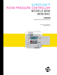
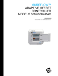
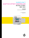
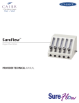
Download Model 8670 SureFlow
Transcript
Model 8670 SUREFLOW TM Room Pressure Controller Operation and Service Manual September 1994 P/N 1980148 Rev. C Model 8670 SUREFLOW TM Room Pressure Controller Operation and Service Manual September 1994 P/N 1980148 Rev. C U.S. AND CANADA Sales & Customer Service: (800) 777-8356/(651) 490-2711 Fax: (651) 490-2874 SHIP TO: TSI Incorporated ATTN: Customer Service 500 Cardigan Road Shoreview, MN 55126 USA OTHER COUNTRIES Sales & Customer Service: (001 651) 490-2711 Fax: (001 651) 490-2874 MAIL TO: TSI Incorporated P.O. Box 64394 St. Paul, MN 55164 USA E-MAIL [email protected] WEB SITE www.tsi.com Copyright - TSI Incorporated/September 1994/All rights reserved. Part number 1980148 Rev. C LIMITATION OF WARRANTY AND LIABILITY Seller warrants that this product, under normal use and service as described in the operator's manual, shall be free from defects in workmanship and material for a period of twenty-four (24) months, or the length of time specified in operator's manual, from the date of shipment to the customer. This limited warranty is subject to the following exclusions: 1. 2. 3. 4. Batteries, hot wire or hot film sensors and certain other components when indicated in specifications are warranted for a period of 90 days from the date of shipment to the customer. With respect to any repair services rendered, seller warrants that the parts repaired or replaced will be free from defects in workmanship and material, under normal use, for a period of 90 days from the date of shipment to the customer. Seller does not provide any warranty on finished goods manufactured by others. Only the original manufacturer's warranty applies. Unless specifically authorized in a separate writing by seller, seller makes no warranty with respect to, and shall have no liability in connection with, any goods which are incorporated into other products or equipment by the Buyer. The foregoing is IN LIEU OF all other warranties and is subject to the conditions and LIMITATIONS stated herein. NO OTHER EXPRESS OR IMPLIED WARRANTY OF FITNESS FOR PARTICULAR PURPOSE OR MERCHANTABILITY IS MADE. THE EXCLUSIVE REMEDY OF THE USER OR PURCHASER, AND THE LIMIT OF THE LIABILITY OF SELLER FOR ANY AND ALL LOSSES, INJURIES, OR DAMAGES IN CONNECTION WITH THIS PRODUCT (INCLUDING CLAIMS BASED ON CONTRACT, NEGLIGENCE, STRICT LIABILITY, OTHER TORT, OR OTHERWISE) SHALL BE THE RETURN OF THE PRODUCT TO THE FACTORY OR DESIGNATED LOCATION AND THE REFUND OF THE PURCHASE PRICE, OR, AT THE OPTION OF SELLER, THE REPAIR OR REPLACEMENT OF THE PRODUCT. IN NO EVENT SHALL SELLER BE LIABLE FOR ANY SPECIAL INCIDENTAL OR CONSEQUENTIAL DAMAGES. NO ACTION, REGARDLESS OF FORM, MAY BE BROUGHT AGAINST THE SELLER MORE THAN ONE YEAR AFTER THE CAUSE OF ACTION HAS ACCRUED. The purchaser and all users are deemed to have accepted the terms of this LIMITATION OF WARRANTY AND LIABILITY, which contains the complete and exclusive limited warranty of seller. This LIMITATION OF WARRANTY AND LIABILITY may not be amended or modified nor may any of its terms be waived except by a writing signed by an authorized representative of seller. SERVICE POLICY Knowing that inoperative or defective instruments are as detrimental to TSI as they are to our customers, our service policy is designed to give prompt attention to any problems. If any malfunction is discovered, please contact your nearest sales office or representative, or call TSI's Customer Service department at (800) 777-8356. ii CONTENTS Page Number PART ONE Introduction ...................................................................................... 1 Chapter 1 Chapter 2 Chapter 3 Getting Started ....................................................................................... 3 How to Use This Manual ........................................................................ 5 Operation ................................................................................................ 7 PART TWO Programming the Instrument .................................................... 13 Chapter 4 Chapter 5 Chapter 6 Chapter 7 Chapter 8 Structure of Instrument ........................................................................... 15 Setpoints Menu....................................................................................... 21 Configure Menu ...................................................................................... 25 Calibration Menu .................................................................................... 29 Control Menu .......................................................................................... 35 PART THREE Diagnostics and Maintenance ................................................... 37 Chapter 9 Chapter 10 Chapter 11 Diagnostics Menu ................................................................................... 39 Maintenance and Repair Parts ............................................................... 47 Troubleshooting ...................................................................................... 49 PART FOUR Appendices ....................................................................................... 57 Appendix A Appendix B Appendix C Appendix D Appendix E Specifications ......................................................................................... 59 Theory of Operation ............................................................................... 61 Control Theory ........................................................................................ 67 Wiring Diagram ....................................................................................... 71 Access Codes......................................................................................... 75 iii PART ONE Introduction Chapters 1, 2 and 3 introduce the SUREFLOW Room Pressure Controller. This part of the manual is written to give a broad overview of the SUREFLOW. It is recommended that everyone read this as a starting point for understanding how to use this manual and how the SUREFLOW operates. Chapter 1 describes what is needed to get started, including proper installation. Chapter 2 explains how to use this manual. Chapter 3 describes the operation of the SUREFLOW from a user's point of view. These chapters are written so that everyone can easily understand them. They are intended to provide a general overview of the SUREFLOW and to provide a reference for more detailed information found in later chapters of this User's Guide. 1 Chapter 1 Getting Started The SUREFLOW Operation and Service Manual describes how to operate, calibrate, configure, maintain and troubleshoot the Model 8670 SUREFLOW Room Pressure Controller. It is recommended that this manual is read thoroughly before using the SUREFLOW. This manual assumes that the SUREFLOW has been properly installed. Refer to Appendix D to check wiring. Refer to the Installation Instructions if there is any question as to whether the SUREFLOW has been properly installed. References to the SUREFLOW keypad and digital display are highlighted in this guide as follows: The font DISPLAY is used to denote menus, menu items, item values and messages as they would appear on the display. The font KEYPAD is used to denote actual keypads on the front panel. Step-by-step instructions are denoted by numbered circles . Actual keys are denoted by a box as follows: MENU Actual displays are denoted by a box as follows: PRESSURE -.00085 "H2O HELP! Technical assistance, repair parts and service: Contact TSI Customer Service department at (800) 777-8356 (U.S. and Canada) or (001 651) 490-2711 (other countries). 3 Chapter 2 How To Use This Manual General Discussion WARNING: Programming the Instrument for the First Time This manual is divided into four parts. Each part is designed to cover a particular area of interest for different people. It is recommended that everyone read the entire User's Guide; however, the following guidelines reference the manual sections which are relevant to your situation: Part Title Who Should Read Chapters One Introduction Everyone 1-3 Two Programming the Instrument Programmers Start-up Personnel Installers Facility Engineers Maintenance Personnel 4-8 Three Diagnostics and Maintenance Service Personnel Maintenance Personnel Facility Engineers 9-11 Four Appendices Design Engineers Consulting Engineers Facility Engineers Every SUREFLOW is factory calibrated; the sensor and controller must therefore be kept as a matched set. If you are unfamiliar with the TSI SUREFLOW products and you need to program the instrument, it is recommended that you read Chapters 1-8. Part One (Chapters 1-3) provides an overview of the instrument. The instrument block diagram shown in Figure 3 of Chapter 4 is an excellent reference to use while programming the instrument. Part Two (Chapters 4-8) details how the SUREFLOW is programmed and describes the items in the SETPOINTS, CONFIGURE, CALIBRATION, and CONTROL menus. This Part is designed to be used as follows: User must read Chapter 4, "Programming the Instrument," first. It shows the user how to use the keypad to program the instrument. Once the user is familiar with the methods needed to program the instrument, the same procedure (i.e., sequence of keystrokes) is used to program any item of the SUREFLOW. The subsequent chapters (5-8) describe the different menu items, but have few step-by-step keystroke procedures. If you are having difficulties programming your SUREFLOW, please contact your authorized TSI Manufacturer's Representative or TSI. 5 Maintaining the SUREFLOW If you are having problems with your SUREFLOW, Part Three (Chapters 9-11) is your main source of reference. However, before you use this part of the manual, it is recommended that you read Part One (Chapters 1-3) and Chapter 4. This will provide you with the background needed to run the DIAGNOSTICS menu to determine the cause of your problems. Chapter 9 describes the tools available in the DIAGNOSTICS menu. The keystrokes needed to use the diagnostics are developed in Chapter 4. Using the DIAGNOSTICS menu should provide you with enough information to determine the source of your problems. Once the user has made this determination, Chapters 10-11 provide suggested courses of action. If you have an error message on the display, the troubleshooting suggestions in Chapter 11 will provide you with guidance to determine the cause of the error message. The DIAGNOSTICS menu will be used frequently to aid in determining the error. If you are still having a problem with your SUREFLOW after using Part Three, contact your authorized TSI Manufacturer's Representative or TSI. Interested in How the SUREFLOW Works? 6 Part Four, the Appendices, describes how the SUREFLOW Room Pressure Controller works. The different appendices describe the measurement and control techniques utilized by TSI. Chapter 2 Chapter 3 Operation The SUREFLOW Room Pressure Controller is easy to use. Its operation is simple and straightforward. All the information you need to know about the controlled Room Pressure is displayed on the controller's front panel. All programming is accessible through the keypad. From an operator's standpoint, the SUREFLOW functions on two levels: 1. The SUREFLOW has a front panel display which provides indication of the Room Pressure and alarm conditions via an alphanumeric display, indicator lights and an audible alarm. 2. The SUREFLOW has front panel controls for testing the unit for proper operation, resetting alarms, silencing alarms and programming the instrument. Specific details about the SUREFLOW front panel display and controls are described on the following pages. The front panel is shown in Figure 1, identifying the display, keys and lights. 7 Figure 1. SUREFLOW Front Panel Display and Controls. 8 Chapter 3 Front Panel Displays Digital Display The alphanumeric digital display indicates the room pressure, status, menu options, and error messages. The display indicates the room pressure continuously, the appropriate status of the control (i.e., normal, alarm, setback, or emergency modes), the menu items as they are selected, and the error messages when they occur. Normal Light The green Normal light indicates that the room pressure is in the normal operating range. The Normal light is on when the room pressure is within the Normal operating deadband of 20 percent of setpoint (in velocity). Caution Light The yellow Caution light indicates a caution condition. The Caution light turns on when the room pressure falls outside the Normal setpoint deadband. When the room pressure reaches the alarm region, the Caution light turns off and the Alarm light turns on. The Caution light will come back on if the pressure returns to Normal setpoint deadband and does not reach setpoint. The Caution light is also on whenever the controller is in the remote setpoint mode. Alarm Light The red Alarm light indicates an alarm condition. The Alarm light turns on when the magnitude of the room pressure falls below the low alarm setpoint or is in the opposite direction. The Alarm light also turns on when the magnitude of the room pressure is above the high alarm setpoint. The Alarm light is accompanied with a message on the display indicating the type of alarm. When the Alarm light is configured for alarm follow condition, the Alarm light remains on until the room pressure returns to normal. When the Alarm light is configured for alarm latched operation, the Alarm light remains on until the room pressure returns to normal and the RESET key has been pressed. Mute Light The yellow Mute light indicates that the audible alarm is disabled. The Mute light turns on when the audible alarm has been disabled. The audible alarm will not sound as long as the Mute light is on. Operation 9 Audible Alarm The audible alarm indicates alarm conditions. The audible alarm sounds continually when the room pressure is in an alarm condition. When the audible alarm is configured for alarm follow operation, the alarm continues to sound until the MUTE key is pressed or the room pressure returns to normal. When the audible alarm is configured for alarm latch operation, the audible alarm remains on until the MUTE key is pressed or the room pressure returns to normal and the RESET key is pressed. The audible alarm tone will beep on and off whenever an emergency condition has been annuciated. This will continue until the emergency condition has been terminated. Front Panel Controls SETBACK key The SETBACK key is used for in-house testing and has no function in the field. EMERGENCY Key The red EMERGENCY key is used to initiate the emergency mode. In this mode, the room is controlled at either maximum negative or maximum positive pressure, depending on the setpoint. In emergency mode, a controller with a positive control setpoint will open the supply or will close the exhaust, depending on what the SUREFLOW is controlling. Conversely, a controller with a negative control setpoint will close the supply or will open the exhaust, depending on what the SUREFLOW is controlling. The display will flash EMERGENCY, the red Alarm light will flash on and off, and the audible alarm will sound on and off. If the EMERGENCY key or the RESET key is pressed during an emergency condition, the unit returns to normal operation. TEST Key The TEST key is used to initiate an instrument self-test. A test sequence is started when the TEST key is pressed. The sequence displays current information including the software version and various setpoints, and tests the display, indicator lights, audible alarm, and internal electronics. RESET Key The RESET key is used to reset the Alarm light, the alarm contacts, and the audible alarm. If the alarms are in the latched mode, the Alarm light, alarm contacts or audible alarm are reset when the room pressure has returned to normal and the RESET key has been pressed. The RESET key is capable of taking the unit out of an emergency condition and is also used to reset error messages. See the troubleshooting guide in Chapter 11 for details. MUTE Key The MUTE key is used to silence and/or disable the audible alarm. An audible alarm can be silenced anytime by pressing the MUTE key. The audible alarm can be disabled by pressing the MUTE key when the audible alarm is not sounding and the yellow Mute light is off. The yellow Mute light turns on when the audible alarm has been disabled. 10 Chapter 3 Keys with Blue Characters The SUREFLOW has four keys with blue print that are used together to program the unit for each application. MENU Key The MENU key is used to gain initial access to the menus when the unit is in the normal operating mode. Once in the menus, the MENU key is used to escape to the next higher level of options. The MENU key is also used to return to the normal operating mode. The different levels are described in detail in Chapter 4. SELECT Key The SELECT key is used to access specific menus and items. Once a characteristic has been chosen, the SELECT key is used to save that property in the unit, and back out to the next higher level. / Arrow Keys The arrow keys are used to scroll through menu choices and possible characteristics to be selected. The characteristics may be numerical values, specific properties, or a bar graph, depending on item type. Operation 11 PART TWO Programming the Instrument Chapters 4, 5, 6, 7 and 8 cover all aspects of programming the SUREFLOW Room Pressure Controller. This part of the manual is written to assist people programming the instrument. TSI realizes that those programming the instrument may have little or no experience with room pressure controllers. For this reason, this part not only describes the procedures to program the instrument, but also describes every menu item. Chapter 4 describes how to program the instrument. Chapter 5 describes the SETPOINTS menu. Chapter 6 describes the CONFIGURE menu. Chapter 7 describes the CALIBRATION menu. Chapter 8 describes the CONTROL menu. References to the SUREFLOW keypads and alphanumeric digital display are highlighted as follows: The font DISPLAY is used to denote menus, menu items, item values and messages as they would appear on the screen. The font KEYPAD is used to denote actual keypads on the front panel. Step-by-step instructions are denoted by numbered circles . Actual keys are denoted by a box as follows: MENU Actual displays are denoted by a box as follows: PRESSURE -.00085 "H2O These symbols are used to show what the actual display will indicate while programming the instrument. If you need further assistance in programming the instrument, contact your authorized TSI Manufacturer's Representative or TSI at (800) 777-8356 (U.S. and Canada) or (001 561) 490-2711 (other countries). 13 Chapter 4 Structure of Instrument Programming Instrument The four keys with blue characters (refer to Figure 2) are used to access all menus for programming/calibration of the SUREFLOW: Figure 2. Access keys. MENU key: Used to gain initial access to the menus when the unit is in the normal operating mode. Once in the menu system, pressing this key always escapes to the previous menu level (without saving data). SELECT key: Used to gain access to specific menus and menu items; also used to save an item value after it has been programmed. Audible and visual confirmation of data being saved is always given. / Used to scroll between menu choices, item choices, or to change item values. arrow keys: The keystroke operation is consistent in all menus. A typical sequence of keystrokes would include: Press MENU to access the main menu. Use the or arrow keys to place the menu cursor on a menu choice. Enter the particular menu chosen by pressing the SELECT key. Use the or arrow keys to scroll to a menu item choice. Press the SELECT key to access an item. The item value is now shown on the second line of the display. Use the or arrow keys to change the item value. 15 Programming Example Save the new value by pressing the SELECT key. Return to normal instrument operation by pressing the MENU key to escape to higher menu levels. In the following example, we will change the low alarm setpoint from .00035 inches H2O to -0.00050 inches H2O: Unit is in normal operation indicating realtime measured room pressure as shown: Press the MENU key to gain access to the main menus as shown: PRESSURE -.00085 “H2O MENU Menu Choices Press the SELECT key to access the SETPOINTS menu: SETPOINTS CONFIGURE SELECT Menu Title First Item Displayed SETPOINTS SETPOINT As illustrated, the menu title is displayed on line 1 of the display, and the first item is displayed on line 2. Press the arrow key until the LOW ALARM item is displayed on line 2 of the display. Second Item Displayed SETPOINTS SETBACK Third Item Displayed 16 SETPOINTS LOW ALARM Chapter 4 Press the SELECT key to access the low alarm setpoint. The item name (LOW ALARM) will now be displayed on line 1 of the display, and the item's current value will be displayed on line 2. SELECT Item Name Item Value LOW ALARM -.00035 "H2O Press the arrow key to change the low alarm setpoint to -0.00050 inches H2O. Item Name Item Value LOW ALARM -.00040 "H2O LOW ALARM -.00045 "H2O LOW ALARM -.00050 "H2O Press the SELECT key to save the new low alarm setpoint. Three short beeps will sound, and the display will indicate that the data is being saved as shown above. SELECT LOW ALARM Saving Data Immediately after the new data is saved, the SUREFLOW will return to the menu level displaying the menu title on the top line of the display and the item name on the bottom line: SETPOINTS LOW ALARM Structure of Instrument 17 WARNING: If the MENU key was pressed instead of the SELECT key, the new data would not have been saved, and the SUREFLOW would have escaped back to the menu level as shown above. Press the MENU key to return to the main menu level: MENU SETPOINTS CONFIGURE Press the MENU key again to return to the normal operating level: MENU Item Name Item Value PRESSURE -.00085 "H2O The following block diagram labels all available items within the SUREFLOW. Using the keystroke procedure described above, all items may be accessed and changed. This block diagram should be used as a reference during start-up and maintenance. 18 Chapter 4 Figure 3. Block Diagram: Items available with SUREFLOW Structure of Instrument 19 Chapter 5 Setpoints Menu The SUREFLOW Room Pressure Controller is a very versatile device which may be adjusted to control and alarm at different setpoints to meet your specific application. This Chapter is a guide to the SETPOINTS menu of the SUREFLOW. This menu is used to select the control, remote, low alarm, high alarm, and no-flow alarm setpoints. Adjusting the setpoints is done by using the keypad operations detailed in Chapter 4 of this manual. The setpoints may also be adjusted using the RS-485 Communications port and the RS-232 Serial Port. Data in the setpoint menu is stored by pressing the SELECT key after a data change has been made. The unit will respond that data is saved by indicating "Saving Data" on the display and sounding three beeps. If you are unfamiliar with the keystroke procedure to program the controller, please read Chapter 4, "Structure of Instrument," for a detailed explanation. Access Code An access code is used to prohibit unauthorized access to the SETPOINTS menu. If you attempt to enter the SETPOINTS menu when the access code is enabled, "Enter Code" flashes on and off on the display. To enter the menu, enter the SETPOINTS menu access code found in Appendix E. If the access code is entered correctly, the SETPOINTS menu will be accessed. Description of the SETPOINTS Menu Items Item Description SETPOINT The SETPOINT function is used to set the control setpoint. The SUREFLOW controller will maintain this room pressure during normal operating conditions. REMOTE SETP The REMOTE SETP function is used to set a remote control setpoint. This function instructs the SUREFLOW to control at the REMOTE SETP setpoint. A REMOTE SETP condition is initiated when the REMOTE SETP contact input has been closed, or a command is received through the RS-485 network. LOW ALARM The LOW ALARM function is used to set the LOW ALARM setpoint. A low room pressure alarm condition is initiated when the magnitude of the room pressure falls below or goes in the opposite direction of the LOW ALARM setpoint. HIGH ALARM The high alarm function is used to set the HIGH ALARM setpoint. A high alarm condition is initiated when the magnitude of the room pressure rises above the HIGH ALARM setpoint. 21 NO-FLO ALARM WARNING: Defaults The NO-FLO ALARM function is used to set a second low alarm setpoint. The magnitude of the NO-FLOW alarm setpoint should be set below the low alarm setpoint to operate as designed. The NO-FLOW ALARM has higher priority than the LOW ALARM. If the NO-FLOW ALARM is set higher than the LOW ALARM, the LOW ALARM is essentially disabled. If the NO-FLOW ALARM is set higher than the control setpoint, the controller will continuously be in a NO-FLOW ALARM mode. The magnitude of the NO-FLOW ALARM must never be set above the control setpoint. ACCESS CODE The ACCESS CODE item is used to select whether an access code is required to enter the SETPOINTS menu. The ACCESS CODE item prevents unauthorized access to the SETPOINTS menu. This item is disabled and is not indicated on the display during initial start-up. The ACCESS CODE is enabled by turning the ACCESS CODE to ON. END OF MENU The END OF MENU item informs the user that the end of the SETPOINTS menu has been reached. The user can press either the SELECT key or the MENU key to back out to the main menu level. The SUREFLOW is shipped with a set of factory default values programmed in memory. These default values are listed in the Setpoint worksheet found in Table 1. Table 1. SUREFLOW Setpoint Defaults Item Range/Options 22 Default Value SETPOINT -.20000 to +.20000 "H2O (-1500 to 1500 FT/MIN) -.00085 "H2O (-100 FT/MIN) REMOTE SETP -.20000 to +.20000 "H2O (-1500 to 1500 FT/MIN) 0 "H2O (0 FT/MIN) LOW ALARM -.20000 to +.20000 "H2O (-1500 to 1500 FT/MIN) OFF HIGH ALARM -.20000 to +.20000 "H2O (-1500 to 1500 FT/MIN) OFF NO-FLO ALARM -.20000 to +.20000 "H2O (-1500 to 1500 FT/MIN) OFF ACCESS CODE ON or OFF OFF Chapter 5 WARNING: Constraints The low and high alarms must be set in the same direction as the setpoint. The SUREFLOW does not allow a positive setpoint and a negative low alarm. There are a number of constraints that prohibit the user from incorrectly adjusting the setpoints. These are as follows: 1. The magnitude of the LOW ALARM setpoint must be set at least 20 ft/min below the control SETPOINT (see Appendix C for relationship between pressure and velocity). The SUREFLOW will not allow the LOW ALARM setpoint to be set any closer. For example, if the control SETPOINT is set at 100 ft/min, the highest the LOW ALARM setpoint can be is -80 ft/min. This is done to prevent nuisance alarms from occurring during natural fluctuations of the system. 2. The magnitude of the HIGH ALARM setpoint must be at set at least 20 ft/min above the control SETPOINT. The SUREFLOW will not allow the HIGH ALARM setpoint to be set any closer. For example, if your control SETPOINT is set at -100 ft/min, the lowest the HIGH ALARM setpoint can be is -120 ft/min. This is done to prevent nuisance alarms from occurring during natural fluctuations of the system. 3. The alarm setpoints automatically follow the same alarm offsets when the SUREFLOW is placed in the REMOTE SETP mode. Consider a unit set up as follows: LOW ALARM -60 FT/MIN (-.00030 "H2O) SETPOINT -100 FT/MIN (-.00085 "H2O) HIGH ALARM -150 FT/MIN (-.00200 "H2O) When this unit is placed in the REMOTE SETP mode where the REMOTE SETP is set to 80 ft/min, the following conditions will be employed: REMOTE SETP LOW ALARM +40 FT/MIN (+.00010 "H2O) REMOTE SETP SETPOINT +80 FT/MIN (+.00055 "H2O) REMOTE SETP HIGH ALARM +130 FT/MIN (+.00150 "H2O) Notice the 40 ft/min difference between the LOW ALARM and SETPOINT was maintained in both the normal and setback modes of operation. Similarly, the 50 ft/min difference between the SETPOINT and the HIGH ALARM was also maintained in both modes. Setpoints Menu 23 Chapter 6 Configure Menu The SUREFLOW may be set up to operate in a variety of configurations. This Chapter is a guide for configuring the SUREFLOW. The CONFIGURE menu is used to select the display time constant, the display units, alarm relay response, the alarm light response, the audible alarm response, the audible alarm disable, the network status, and the network address. Data in the CONFIGURE menu is stored by pressing the SELECT key after a data change has been made. The unit will respond that the data is saved by indicating, "Saving Data" and sounding three beeps. If you are unfamiliar with the keystroke procedure to program the controller, please read Chapter 4, "Structure of Instrument," for a detailed explanation. Access Code An access code is used to prohibit unauthorized access to the CONFIGURE menu. If you attempt to enter the CONFIGURE menu when the access code is enabled, "Enter Code" flashes on and off on the display. To enter the menu, enter the CONFIGURE menu access code found in Appendix E. If the access code is entered correctly, the CONFIGURE menu will be accessed. WARNING: Description of the CONFIGURE Menu Items For accurate measurement and control of room pressure, the ELEVATION item of the CONFIGURE menu must be properly programmed. Item Description TIME CONST. The TIME CONST. item is used to set the display filtering period. The display filtering period is the period of time over which the room pressure has been filtered before being displayed. The TIME CONST. item value may be set between 0.75 and 40 seconds. The higher the filtering value, the more stable the display. UNITS The UNITS item is used to select the choice of UNITS displayed on the controller. The choices for the SUREFLOW are English (inches H2O or ft/min) or metric (Pa, mm H2O or m/s) units of measure. 25 ALARM RELAYS The ALARM RELAYS item is used to select whether the low, high, and no-flow relays latch in an alarm condition (LATCHED) or follow in an alarm condition (UNLATCHED). When the alarm latch is selected, the alarm relay contacts close in an alarm condition and remain closed until the room pressure returns to normal and the RESET key is pressed. When alarm follow (UNLATCHED) is selected, the alarm relay contacts close in an alarm condition and open when the room pressure returns to normal. ALARM LIGHT The ALARM LIGHT item is used to select whether the alarm light latches in an alarm condition (LATCHED) or follows in an alarm condition (UNLATCHED). The display will indicate the appropriate alarm as follows: ALARM=LOW ALARM=HIGH ALARM=NO-FLO The LOW, HIGH, and NO-FLO will be flashing on and off to raise attention to the alarm condition. When an alarm latch is selected, the Alarm light turns on and the display indicates the alarm. The Alarm light will remain on and the display will indicate the alarm condition until the room pressure returns to normal and the RESET key is pressed. When alarm follow (UNLATCHED) is selected the Alarm light turns on and the display indicates the appropriate alarm type until the room pressure returns to normal. 26 AUD. ALARM The AUD. ALARM item is used to select whether the audible alarm latches in an alarm condition (LATCHED) or follows in an alarm condition (UNLATCHED). When alarm latch is selected, the audible alarm turns on in an alarm condition and remains on until the room pressure returns to normal and the RESET key is pressed. When alarm follow (UNLATCHED) is selected, the audible alarm turns on in an alarm condition and off when the room pressure returns to normal. AUD. DISABLE The AUD. DISABLE item is used to select whether the audible alarm can (ON) or cannot (OFF) be disabled from the keypad. NETWORK STAT The NETWORK STAT item is used to select the status of the RS-485 network. The status is either OFFLINE or ONLINE. If the RS-485 communication is being used, the NETWORK STAT must be selected as ONLINE. NETWORK ADDR The NETWORK ADDR item is used to select the address of the individual SUREFLOW unit when it is used as part of a networked RS-485 system. Chapter 6 AOUT FACTOR The AOUT FACTOR item is used to select the resolution range of the analog output. A setting of 1 corresponds to .10000 to .10000 "H2O while a setting of 10 corresponds to -.01000 to .01000 "H2O and a setting of 100 corresponds to -.00100 to .00100 "H2O (see Figure 4 below). With these ranges, 5 volts or 12 mA represents a 0 room pressure differential. With a setting of 1, 10 volts or 20 mA represents a pressure differential of .10000 "H2O. If the pressure is outside the range, the output remains at maximum or minimum depending on the direction of flow. Figure 4. Analog Output Versus Room Pressure ELEVATION Configure Menu The ELEVATION item is used to enter the elevation of the lab above sea level. This item has a range of 0-10,000 feet with 1,000-foot increments. The pressure value is corrected due to changes in air density at different elevations. 27 Defaults ACCESS CODE The ACCESS CODE item is used to select whether an access code is required to enter the CONFIGURE menu. The ACCESS CODE item prevents unauthorized access to the CONFIGURE menu. This item is disabled and is not indicated on the display during initial start-up. The ACCESS CODE is enabled by turning the ACCESS CODE to ON. END OF MENU The END OF MENU item informs the user that the end of the CONFIGURE menu has been reached. The user can press either the SELECT key or the MENU key to back out to the main menu level. The SUREFLOW is shipped with a set of factory default values already programmed in memory. These default values are listed in the Configuration worksheet found in Table 2. Table 2. SUREFLOW Configuration Defaults Item Range/Option Default Value TIME CONST. 0.75, 1, 2, 3, 5, 10, 20 or 40 seconds 20 seconds UNITS FT/MIN, m/s, "H2O, mm H2O or Pa "H2O ALARM RELAYS LATCHED or UNLATCHED LATCHED ALARM LIGHT LATCHED or UNLATCHED LATCHED AUD. ALARM LATCHED or UNLATCHED LATCHED AUD. DISABLE ON or OFF ON NETWORK STAT ONLINE or OFFLINE OFFLINE NETWORK ADDR 1 through 250 1 AOUT FACTOR 1, 10, 100 1 ELEVATION 0-10,000 0 ACCESS CODE ON or OFF OFF 28 Chapter 6 Chapter 7 Calibration Menu The SUREFLOW Room Pressure Controller is calibrated at the factory. The sensor and controller must be kept as a matched set. A yellow warning label is attached to every SUREFLOW indicating this as follows: WARNING: Unit is factory calibrated. Controller and sensor must be installed as a matched set. This label is to be removed after installation is complete. The SUREFLOW Room Pressure Controller can be calibrated to special systems. This should be done only if the system is an unusual case. This chapter is a guide to calibrating the SUREFLOW. All of the calibration must be done through the front panel keypad. The CALIBRATION menu is used to select the SENSOR SPAN item. Data in the CALIBRATION menu is stored by pressing the SELECT key after a data change has been made. The unit will respond that the data is saved by indicating "Saving Data" on the display and sounding three beeps. If you are unfamiliar with the keystroke procedure to program the controller, please read Chapter 4, "Structure of Instrument," for a detailed explanation. Access Code An access code is used to prohibit unauthorized access to the CALIBRATION menu. If you attempt to enter the CALIBRATION menu when the access code is enabled, "Enter Code" flashes on and off on the display. To enter the CALIBRATION menu, enter the CALIBRATION menu access code found in Appendix E. If the access code is entered correctly, the CALIBRATION menu will be accessed. Description of the CALIBRATION Menu Items Item Description SENSOR SPAN The SENSOR SPAN item is used to calibrate the SUREFLOW velocity sensors to the average room pressure velocity as measured by a portable air velocity meter. ACCESS CODE The ACCESS CODE item is used to select whether an access code is required to enter the CALIBRATION menu. The ACCESS CODE item prevents unauthorized access to the CALIBRATION menu. This function is enabled and is not indicated on the display during initial start-up. 29 END OF MENU Defaults Performing the CALIBRATION Function WARNING: The END OF MENU item informs the user that the end of the CALIBRATION menu has been reached. The user can press either the SELECT key or the MENU key to back out to the main menu level. The SUREFLOW is shipped with a set of factory default values already programmed in memory. In the CALIBRATION menu, the only relevant default parameter is the ACCESS CODE item which can be either ON or OFF with a factory default of ON. The following items are needed to calibrate the SUREFLOW: Portable Air Velocity Meter such as TSI VELOCICALC Plus, VELOCICALC, or VELOCICHECK. NO FIELD CALIBRATION IS NEEDED! The SUREFLOW Room Pressure Controller is calibrated at the factory. The sensor and controller must be kept as a matched set. The calibration function provides the user with the ability to manually change the calibration of the pressure sensor. THE CALIBRATION OF THE ROOM PRESSURE CONTROLLER MUST NEVER BE CHANGED WITHOUT ASSISTANCE FROM THE TSI FACTORY! Contact TSI for assistance in determining your control problem and for instructions on how to recalibrate your unit. Incorrectly changing the calibration of this instrument may result in poor control or no control at all. Unit is in normal operation indicating realtime measurement of room pressure as shown: Press the MENU key to gain access to the menu as shown: PRESSURE -.00085 "H2O MENU SETPOINTS CONFIGURE Press the arrow key until the cursor is at the CALIBRATION menu option: SETPOINTS CONFIGURE Second Menu Choice Third Menu Choice 30 CONFIGURE CALIBRATION Chapter 7 Press the SELECT key to gain access to the CALIBRATION menu. SELECT CALIBRATION SENSOR SPAN Press the SELECT key to initiate the SENSOR SPAN sequence. The display will respond with the following response: Place the air velocity meter sensor in an opening between the controlled room and the reference space, (i.e. a laboratory and an adjoining corridor). This opening is normally a door between the laboratory and hallway opened approximately one inch. Tape a small piece of tissue in the opening or use smoke to determine direction of flow. Make sure the direction is correct before proceeding. Use the arrow keys to adjust the SENSOR SPAN value to match the average velocity indicated from the air velocity meter measurements. Press the SELECT key to save the SENSOR SPAN calibration data in memory. Three short beeps will sound, and the display will indicate that the data is being saved as shown above. SELECT SENSOR SPAN 82 FT/MIN SELECT SENSOR SPAN Saving Data Immediately after the new data is saved, the SUREFLOW will return to the menu level displaying the menu title on the top line and the item name on the bottom line: CALIBRATION SENSOR SPAN WARNING: If the MENU key is pressed instead of the SELECT key, the SENSOR SPAN is not saved, and the SUREFLOW will escape to the menu level. WARNING: If it is desired to escape from the SENSOR SPAN calibration sequence at any time during the procedure, press the MENU key, and the SUREFLOW will escape back to the menu level as shown above. WARNING: If you plan to operate at both positive and negative pressure differentials, this procedure must be repeated at both positive and negative pressure differentials. Calibration Menu 31 Check the calibration. Escape back to the normal operating level, and verify that measured room pressure on the SUREFLOW is close to the velocity measured by the air velocity meter. Use the following steps to escape to the normal operating level for verification: MENU CALIBRATION CONTROL MENU VELOCITY 100 FT/MIN If the velocities do match, go to step 10. If the SUREFLOW velocity does not match the air velocity meter measurement, the SENSOR SPAN function must be repeated. Obtain direct access to the SENSOR SPAN item using the following keystrokes: MENU SETPOINTS CONFIGURE SETPOINTS CONFIGURE CONFIGURE CALIBRATION SELECT CALIBRATION SENSOR SPAN Repeat steps 3 through 6 to adjust the SENSOR SPAN. 32 Chapter 7 WARNING: Calibrating the span on the SUREFLOW may be an iterative process that takes 1 3 trials to get an accurate calibration. You must check the calibration after each trial until an accurate calibration is verified. Remove the yellow warning label from the SUREFLOW. Calibration Menu 33 Chapter 8 Control Menu The SUREFLOW may be set up to control room pressure at different sensitivities and different speeds for maximum performance. This Chapter is a guide for setting up the control parameters for the SUREFLOW. The CONTROL menu is used to select the control SENSITIVITY and the control SPEED. Data in the CONTROL menu is stored by pressing the SELECT key after a data change has been made. The unit will respond that the data is saved by indicating "Saving Data" on the display and sounding three beeps. If you are unfamiliar with the keystroke procedure to program the controller, please read Chapter 4, "Structure of Instrument," for a detailed explanation. Access Code An access code is used to prohibit unauthorized access to the CONTROL menu. If you attempt to enter the CONTROL menu when the access code is enabled, "Enter Code" flashes on and off on the display. To enter the menu, enter the CONTROL menu access code found in Appendix E. If the access code is entered correctly, the CONTROL menu will be accessed. General Discussion Description of the CONTROL Menu Items The SUREFLOW uses both integral and PID control methods. Integral control is used to maintain the operating setpoint with stability for natural system fluctuations such as static pressure shifts. PID control is used to return to the operating setpoint with optimal speed when responding to large disturbances. Once the SUREFLOW is in PID control, it continues to control in this mode until the operating setpoint is met. Item Description SENSITIVITY The SENSITIVITY item is used to select the integral deadband which determines where the controller uses integral control only, and where the controller enters PID control. When this item is selected, a bar graph will be shown on the display. There are 10 possible bars that represent 10 ft/min each. Starting from the right side (with + sign), 10 bars displayed indicates no deadband and the controller will always use PID control (see WARNING below). With 9 bars displayed, the integral deadband is 10 ft/min; with 8 bars, the deadband is 20 ft/min; and so on to no bars displayed where the deadband is 100 ft/min. 35 For example, with 8 bars displayed and an operating setpoint of 100 ft/min, the integral deadband is between 80 and 120 ft/min. When the measured room pressure velocity is within this range, integral control is used. However, when the room pressure velocity falls below 80 ft/min or rises above 120 ft/min, PID control is used until the operating setpoint is reached. WARNING: When the SENSITIVITY is set on 10 bars, the system is always in PID control. It is recommended that the SENSITIVITY be set at 9 bars or less. SPEED The SPEED item is used to select the speed of control. When this item is selected, a bar graph is shown on the display. There are 10 bars, each one representing 10% of optimal speed. Starting from the right side (with + sign), 10 bars displayed indicates 100% of maximum speed. This is the fastest the controller will operate. With 9 bars displayed, the controller operates at 90% of optimal speed; with 8 bars, the controller operates at 80% of optimal; and so on. Defaults ACCESS CODE The ACCESS CODE item is used to select whether an access code is required to enter the CONTROL menu. The ACCESS CODE item prevents unauthorized access to the CONTROL menu. This item is disabled and is not indicated on the display during initial start-up. The ACCESS CODE is enabled by turning the ACCESS CODE to ON. END OF MENU The END OF MENU item informs the user that the end of the CONTROL menu has been reached. The user can press either the SELECT key or the MENU key to back out to the main menu level. The SUREFLOW is shipped with a set of factory default values already programmed in memory. These default values are listed in the Control worksheet found in Table 3. Table 3. SUREFLOW Control Defaults Item Range/Options SENSITIVITY 0 to 100 FT/MIN Default Value 50 ft/min (5 bars) SPEED 100% to 10% 50% (5 bars) ACCESS CODE ON or OFF OFF 36 Chapter 8 PART THREE Diagnostics & Troubleshooting Chapters 9, 10 and 11 cover all aspects of troubleshooting and maintenance of the SUREFLOW Room Pressure Controller. This part is written to give maximum help to the person maintaining, diagnosing or troubleshooting the control system. TSI realizes that many users of TSI equipment have little or no experience with room pressure variable air volume controls. Chapter 9 describes the diagnostics menu. The diagnostics menu is a great help when troubleshooting problems. Chapter 10 describes routine maintenance and repair parts. Chapter 11 describes troubleshooting the SUREFLOW Room Pressure Controller. Chapters 9 and 11 are used together to both diagnose and troubleshoot the system. If you have an idea of the cause of the problem, review Chapter 11 to see if the symptom is covered. If you have no idea what the problem may be, start with Chapter 9 to diagnose possible causes. Troubleshooting the majority of problems can usually be quickly narrowed to one area if the following question can be answered: Are all the system components working? If no, see "Hardware Symptoms" section in Chapter 11 to check for proper wiring and installation of components. If yes, see "Software Symptoms" section in Chapter 11. The diagnostics and troubleshooting are very thorough and should resolve most problems the user may encounter. If you need assistance or further explanation, contact TSI. TSI is committed to providing not only high quality products, but also outstanding service. Please have the following information available prior to contacting your authorized TSI Manufacturer's Representative or TSI at (800) 777-8356 (U.S. and Canada) or (001 651) 490-2711 (other countries): -Model number of unit -Revision level -Software revision level -Serial number -Building where unit is installed The above information will greatly reduce troubleshooting and maintenance time. 37 Chapter 9 Diagnostics Menu The SUREFLOW is provided with a complete set of built-in diagnostics for easy determination of possible problems. This Chapter is a guide for using the DIAGNOSTICS menu in the SUREFLOW. The DIAGNOSTICS menu is used to check the actuator operation, the analog output, the no-flow alarm relay, the low alarm relay, the high alarm relay, the remote setpoint contact input, the emergency contact input, the sensor operation, and the control coefficients. The AUTOTUNE function is also located in the DIAGNOSTICS menu. Please refer to Chapter 11, "Troubleshooting," of this User's Guide for suggestions on possible problems. Much of the data in the DIAGNOSTICS menu may be changed but is not saved. Data that may be saved in the DIAGNOSTICS menu is stored by pressing the SELECT key after a data change made. The unit will respond that the data is saved by indicating, "Saving Data" and sounding three beeps. If you are unfamiliar with the keystroke procedure to program the controller, please read Chapter 4, "Structure of Instrument," for a detailed explanation. Access Code An access code is used to prohibit unauthorized access to the DIAGNOSTICS menu. If you attempt to enter the DIAGNOSTICS menu when the access code is enabled, "Enter Code" flashes on and off on the display. To enter the menu, enter the DIAGNOSTICS menu access code found in Appendix E. If the access code is entered correctly, the DIAGNOSTICS menu will be accessed. Description of the DIAGNOSTICS Menu Items Item Description CONTROL OUTP OUTPthe control The CONTROL OUTP itemCONTROL is used to vary output signal to the actuator/damper (or motor speed drive). When this item is entered, a number will be shown on the display indicating the last control output value. The value displayed ranges from 0 to 255. Pressing the arrow key should adjust the control device and decrease the displayed value. Pressing the arrowkey should adjust the control device and increase the displayed value. If the damper does not move when the arrow keys are pressed, this indicates that something is wrong with the control signal, the wiring, the actuator, or the damper. Escaping from this item is done only by pressing the MENU key. The control output will return to normal control operation when the MENU key is pressed. 39 WARNING: The CONTROL OUTP function should not be used while experiments are being performed in the laboratory. A closed damper may create dangerously low air flows while an opened damper may create dangerously high air flows thus not maintaining a safe room pressure. ANALOG OUTP The ANALOG OUTP item is used to vary the analog output from the SUREFLOW unit. When this item is entered, a number will be shown on the display indicating the last analog output value. The value displayed ranges from 0 to 255. The value 255 corresponds to the lowest voltage (current) output and 0 corresponds to the highest voltage (current) output. Pressing the arrow key will decrease the analog output and increase the value displayed. Pressing the arrow key will increase the analog output and decrease the value displayed. The ANALOG OUTP function can be used in conjunction with a volt meter to verify the analog output is correct. Escaping from this item is done only by pressing the MENU key. The analog output will return to the value corresponding to the measured room pressure when the MENU key is pressed. NO-FLO RELAY The NO-FLO RELAY item is used to change the state of the no-flow alarm relay. When this item is entered, the display will indicate either OPEN or CLOSED. The arrow keys are used to toggle the state of the relay. The arrow key is used to OPEN the alarm contact. The arrow key is used to CLOSE the alarm contact. When the contact is closed, the NO-FLO RELAY should be in an alarm condition. Escaping from this item is done only by pressing the MENU key. The SUREFLOW will return the NO-FLO RELAY to its state prior to entering this item when the MENU key is pressed. LOW RELAY The LOW RELAY item is used to change the state of the low alarm relay. When this item is entered, the display will indicate either OPEN or CLOSED. The arrow keys are used to toggle the state of the relay. The arrow key is used to OPEN the alarm contact. The arrow key is used to CLOSE the alarm contact. When the contact is closed, the LOW RELAY should be in an alarm condition. Escaping from this item is done only by pressing the MENU key. The SUREFLOW will return the LOW RELAY to its state prior to entering this item when the MENU key is pressed. 40 Chapter 9 HIGH RELAY The HIGH RELAY item is used to change the state of the high alarm relay. When this item is entered, the display will indicate either OPEN or CLOSED. The arrow keys are used to toggle the state of the relay. The arrow key is used to OPEN the alarm contact. The arrow key is used to CLOSE the alarm contact. When the contact is closed, the HIGH RELAY should be in an alarm condition. Escaping from this item is done only by pressing the MENU key. The SUREFLOW will return the HIGH RELAY to its state prior to entering this item when the MENU key is pressed. Diagnostics Menu SETBACK IN The SETBACK IN item is used to read the current state of the remote setpoint contact input. When this item is entered, the display will indicate either OPEN or CLOSED. If the display indicates CLOSED, the SUREFLOW has been put into setback mode through the contact input. If the display indicates OPEN, the SUREFLOW has not been put into setback mode through the contact input. However, the SUREFLOW may still be in setback mode if it has been initiated through the RS-485 network. Escaping from this item is done only be pressing the MENU key. EMERGENCY IN The EMERGENCY IN item is used to read the current state of the emergency contact input. When this item is entered, the display will indicate either OPEN or CLOSED. If the display indicates CLOSED, the SUREFLOW has been put into emergency mode through the contact input. If the display indicates OPEN, the SUREFLOW has not been put into emergency mode through the contact input. However, the SUREFLOW may still be in emergency mode if it has been initiated through the keypad or the RS-485 network. Escaping from this item is done only be pressing the MENU key. SENSOR A/D The SENSOR A/D item is used to verify that the controller is receiving a signal from the sensor. When this item is entered, a number will be indicated on the display. The value of the number represents the sensor voltage. The actual value displayed is relatively unimportant. It is more important to notice changes in the displayed value which indicates the sensor is working correctly. An easy test to verify sensor operation includes blocking the sensor opening by putting your hand over it and observing a large change in the displayed number. Escaping from this item is done only be pressing the MENU key. CHANGE Kc The CHANGE Kc item is used to read and change (see WARNING below) the gain control coefficient. When this item is entered, a value for Kc is indicated on the display. If the SUREFLOW is not controlling correctly, the unit may have an inappropriate gain control coefficient. 41 WARNING: The CHANGE Kc item provides the user with the ability to manually change the Kc value. THE Kc VALUE MUST NEVER BE CHANGED WITHOUT ASSISTANCE FROM THE TSI FACTORY! Contact TSI for assistance in determining your control problem and for instructions on how to change the Kc value. Incorrectly changing the Kc value may result in poor control or no control at all. CHANGE Ti WARNING: The CHANGE Ti item provides the user with the ability to manually change the Ti value. THE Ti VALUE MUST NEVER BE CHANGED WITHOUT ASSISTANCE FROM THE TSI FACTORY! Contact TSI for assistance in determining your control problem and for instructions on how to change the Ti value. Incorrectly changing the Ti value may result in poor control or no control at all. CHANGE Td WARNING: The AUTOTUNE item is used to select the optimal control coefficients for a specific laboratory. The AUTOTUNE function should only be used when high-speed response is needed for room pressure control. The SPEED function should be used in normal conditions to adjust response time. The AUTOTUNE function provides the operator with the ability to set up the PID coefficients for optimum control. THE AUTOTUNE FUNCTION SHOULD NOT BE RUN WITHOUT ASSISTANCE FROM THE TSI FACTORY. Contact TSI for assistance. ACCESS CODE 42 The CHANGE Td item is used to read and change (see WARNING below) the derivative control coefficient. When this item is entered, a value for Td is indicated on the display. If the SUREFLOW is not controlling correctly, the unit may have an inappropriate derivative control coefficient. The CHANGE Td item provides the user with the ability to manually change the Td value. THE Td VALUE MUST NEVER BE CHANGED WITHOUT ASSISTANCE FROM THE TSI FACTORY! Contact TSI for assistance in determining your control problem and for instructions on how to change the Td value. Incorrectly changing the Td value may result in poor control or no control at all. AUTOTUNE WARNING: The CHANGE Ti item is used to read and change (see WARNING below) the integral control coefficient. When this item is entered, a value for Ti is indicated on the display. If the SUREFLOW is not controlling correctly, the unit may have an inappropriate integral control coefficient. The ACCESS CODE item is used to select whether an access code is required to enter the DIAGNOSTICS menu. The ACCESS CODE item prevents unauthorized access to the DIAGNOSTICS menu. This item is disabled and is not indicated on the display during initial start-up. The ACCESS CODE is enabled by turning the ACCESS CODE item ON. Chapter 9 END OF MENU Defaults The END OF MENU item informs the user that the end of the DIAGNOSTICS menu has been reached. The user can press either the SELECT key or the MENU key to back out to the main menu level. The SUREFLOW is shipped with a set of factory default values already programmed in memory. In the DIAGNOSTICS menu, the only relevant default parameter is the ACCESS CODE item which can be either ON of OFF with a factory default of OFF. Performing the AUTOTUNE function The purpose of the AUTOTUNE function is to find the optimal control coefficients for each particular room pressure. The optimal coefficients provide the SUREFLOW with the information needed for the fastest possible speed of response for stable operation of each specific room. WARNING: The AUTOTUNE function must never be performed while an experiment or any work in the room is in progress. WARNING: If the system is oscillating or is unstable, lower the SPEED before entering the AUTOTUNE function. WARNING: During the AUTOTUNE sequence, the SUREFLOW will completely close the damper, completely open the damper, and measure the system step response. The supply and exhaust air system must be fully installed and operational before performing the AUTOTUNE procedure. The AUTOTUNE function must never be performed while an experiment is in process. The AUTOTUNE sequence will fully open the damper creating potentially hazardous high air flows and will fully close the damper creating potentially dangerous low air flows. Gain access to the AUTOTUNE item using the keypad starting from normal operation. Press the MENU key to gain access to the main menu as shown. PRESSURE -.00085 "H2O MENU SETPOINTS CALIBRATION Diagnostics Menu 43 Press the arrow key until the cursor is at the DIAGNOSTICS menu option. SETPOINTS CALIBRATION CALIBRATION CONFIGURE CONFIGURE CONTROL CONTROL DIAGNOSTICS Press the SELECT key to access the CONTROL menu. SELECT DIAGNOSTICS CONTROL OUT Press the arrow key until the AUTOTUNE item is shown on the display. DIAGNOSTICS ANALOG OUTP . . . DIAGNOSTICS AUTOTUNE 44 Chapter 9 Press the SELECT key to initiate the AUTOTUNE sequence. The display will respond with a message and a countdown to wait until the sequence is complete. SELECT AUTOTUNE wait...185 The AUTOTUNE function takes 185 seconds to perform. The above message will remain on the display until the countdown has reached 1 second. At that time, the SUREFLOW will inform the user that the AUTOTUNE function is complete with the following message: AUTOTUNE Finished The SUREFLOW automatically returns to normal operation upon completion of the AUTOTUNE function. Diagnostics Menu 45 Chapter 10 Maintenance and Repair Parts The Model 8670 SUREFLOW Room Pressure Controller requires minimal maintenance. Periodic inspection of system components as well as an occasional pressure sensor cleaning are all that are needed to insure that the Model 8670 is operating properly. System Component Inspection Periodically inspect the various system components for proper performance and signs of excessive wear. Pressure Sensor Cleaning The pressure sensor consists of two velocity sensors (see Appendix C for a full technical description). Significant build-up of contaminants including dust and dirt on the velocity sensors can degrade their performance and throw them out of calibration. It is recommended that the velocity sensors be periodically inspected for accumulation of contaminants. The frequency of these inspections is dependent upon the quality of the air being drawn across the sensor. Quite simply, if the air is dirty, the sensors will require more frequent inspection and cleaning. WARNING: Turn off power to the Model 8670 prior to cleaning the velocity sensors. WARNING: Do not use compressed air to clean the velocity sensors. Visually inspect the velocity sensors. The air flow orifice should be free of obstructions. The small, cylindrical, ceramic sensor protruding from the orifice wall should be white and free of accumulated debris. Accumulations of dust or dirt can be removed with a soft-bristled brush (such as an artist's brush). Water, alcohol, acetone, or trichlorethane may be used as a solvent to remove other contaminants if required. WARNING: Do not attempt to scrape contaminants from the velocity sensors. The velocity sensors are quite durable; however, scraping may cause mechanical damage and possibly break the sensor. Mechanical damage due to scraping voids the sensor warranty. WARNING: Use extreme care when cleaning the velocity sensors. The ceramic sensor may break if excessive pressure is applied or if the cleaning apparatus abruptly impacts the sensor. 47 Replacement Parts All components of the Model 8670 are field replaceable. Contact TSI Industrial Test Instruments Group at (800) 777-8356 (U.S. and Canada) or (001 651) 490-2711 (other countries) or your nearest TSI Manufacturer's Representative for replacement part pricing and delivery. Part Number Description 800242 800118 800199 800119 800321 800311 800414 800420 800116 Pressure Controller Electric Actuator Controller Output Cable Electric to Pneumatic Interface Pressure Sensor Sensor Cable Transformer Cable Transformer Pneumatic Actuator The pressure sensor and controller must be kept as a matched pair. They must therefore be ordered together. 48 Chapter 10 Chapter 11 Troubleshooting The SUREFLOW Room Pressure Controller is straightforward and understandable by personnel who have experience with electronic controls. To assist the person working on a problem, TSI has developed a list of the most likely causes of problems. The troubleshooting chapter is broken into two parts: hardware symptoms and software symptoms. Hardware symptoms are related to control system installation or defective components--either TSI or accessory components. In some cases, the laboratory configuration will affect the operation of the controller. The software symptom section is an aid to help the control system operate at optimum performance. Control performance can be affected by the supply air system and the exhaust air system. Often times, the design of the laboratory prohibits optimum system performance. The software symptom section will decrease the system problems due to design or installation. 49 Hardware Symptom Possible Cause Corrective Action Fuse is blown. Measure voltage at pins 1 and 2 on SUREFLOW 10-pin connector. The voltage should nominally be 24 VDC when using electric actuators and 24 VAC when using pneumatic actuators or motor speed drives. If 24 volts is present, unplug 10-pin connector from controller for 15 seconds. The fuse automatically resets. Plug back in and check display. If display is still blank, check all wiring, etc. If no fault is found, replace controller and sensor. No power to controller. Is circuit breaker on? Does transformer primary measure 110 VAC? Does transformer secondary measure 24 VAC? Is there 24 VAC between pins 1 and 2 on the electric actuator or E/P interface? Is there 24 VDC between pins 3 and 4 of the electric actuator? Is there 24 VAC between pins 3 and 4 of the E/P interface? Controller is defective. If 24 VDC (24 VAC for motor-speed drive version) is between pins 1 and 2 of the controller and you have reset the fuse, the controller is probably defective. Replace controller and sensor. Incorrect wiring. Verify correct wiring (see control wiring diagram in Appendix D). Controller must be wired exactly as shown. No controller output signal. Go into DIAGNOSTICS menu, CONTROL OUTP item. See Chapter 9 for CONTROL OUTP description. Measure the voltage on pins 5 and 6 (control output). Voltage should go up as the display value decreases. If the output does not change, the controller is defective. Display is blank. Control system is not controlling. Hardware Symptom Possible Cause Corrective Action Bad actuator or E/P (damper doesn't move). Go into DIAGNOSTICS menu, CONTROL OUTP item. See Chapter 9 for CONTROL OUTP description. If damper moves, actuator is installed and operating correctly. If damper doesn't move, check that: -Jumper is installed correctly on actuator or on E/P. -Damper is not physically stuck. -Electric actuator is current limited. If damper is physically stuck, either kill power to actuator or move damper in opposite direction to restore motor power (motor is current limited). "SENSOR ERROR" flashing on display. Defective variable frequency drive (VFD) Go into DIAGNOSTICS menu, CONTROL OUTP item. See Chapter 9 for CONTROL OUTP description. Measure the voltage on pins 5 and 6 (control output). Voltage should go up as the display value decreases. If the output does not change, the controller is defective. Poor sensor connections. Verify that sensor cable is correctly plugged in at controller and sensor. Connector is polarized but can be forced on backwards. Hardware Symptom Possible Cause Corrective Action Defective sensor. Disconnect the sensor cable from the back of the controller. Depress the latching piece on the connector to pull it out. Use an ohmmeter to measure the resistance between the cable wires indicated in figure below. The resistance between pins 3 and 4 should be between 15 and 25 ohms. The resistance between pins 2 and 4 should be between 680 and 720 ohms. If resistance does not measure correctly, verify that sensor cable is good. See figure below. Defective sensor cable. Verify wire is terminated the same on both ends of cable. Test sensor cable with an Ohmmeter to ensure that cable terminations are good. See figure below. Wire colors must match pin 1 to 1, pin 4 to 4. "DATA ERROR" flashing on display. Controller was hit by electrical disturbance. All data may be lost or changed. Review all configuration parameters. DATA ERROR is removed by pressing the RESET key. "CAL ERROR" flashing on display. Controller was hit by electrical disturbance. Calibration data is corrupted. Send sensor and controller to TSI for recalibration. Remote emergency doesn't work. Incorrect wiring or defective switch. Disconnect remote wires from controller. Verify wiring with an Ohmmeter by switching the emergency switch open and closed. If operational, reconnect to controller. Defective controller. Verify wiring and switch are good. Enter DIAGNOSTICS menu, EMERGENCY IN item. Display will indicate OPEN or CLOSED. Toggle the remote emergency switch, and display should change between OPEN and CLOSED (See Chapter 9 for EMERGENCY IN description). If no response, replace controller and sensor. Hardware Symptom Possible Cause Corrective Action Remote setback doesn't work. Incorrect wiring or defective switch. Disconnect remote wires from controller. Verify wiring with an Ohmmeter by switching the setback switch open and closed. If operational, reconnect to controller. Defective controller. Verify wiring and switch are good. Enter DIAGNOSTICS menu, SETBACK IN item. Display will indicate OPEN or CLOSED. Toggle the remote setback switch, and display should change between OPEN and CLOSED (See Chapter 9 for SETBACK IN description). If no response, replace controller and sensor. Network status is OFFLINE. Go into CONFIGURE menu, NETWORK STAT item. The network status must be OFFLINE for the RS-232 to operate. Incompatible software. Data sent to controller may be in form that the SUREFLOW cannot recognize. Network status is ONLINE. Go into CONFIGURE menu, NETWORK STAT item. The network status must be ONLINE for the RS-485 to operate. Incorrect network address. The network address at the building automation system and at the controller must match. The network address must be unique for each controller. Incompatible software. Data sent to controller may be in form that the SUREFLOW cannot recognize. Alarms may be off. Press TEST key. The individual alarm setpoints will be indicated. Incorrect wiring. Check the wiring from SUREFLOW relay's output to the device that is monitoring the relays. Controller does not respond to RS-232 communications. Controller does not respond to RS-485 communications. Alarm relays don't work. Hardware Symptom Analog output doesn't work properly. Possible Cause Corrective Action Relay may be defective. Enter the DIAGNOSTICS menu and select NO-FLOW, LOW or HIGH RELAY item to be checked. Manually activate the relay. See Chapter 9 for NO-FLOW, LOW or HIGH RELAY descriptions. If controller does not respond, disconnect device connected to relay. Repeat relay check. If controller responds, the device connected is incompatible or defective. If controller does not respond, controller is defective. Replace controller and sensor. Controller is connected to incompatible equipment. Enter the DIAGNOSTICS menu, ANALOG OUTP item. A number is displayed. Pressing the arrow key increases the number and decreases the voltage output. Pressing the arrow key decreases the number and increases the voltage output. If no change occurs, disconnect the analog out device and repeat above procedure. If voltage now changes, the controller is good, and the external device is defective. If no change occurs, controller is defective (see Chapter 9 for ANALOG OUTP description). Replace controller and sensor. Software Symptom Possible Cause Corrective Action The displayed pressure fluctuates. Time constant is very short. Lengthen the time constant by entering the CONFIGURATION menu, TIME CONST. item (see Chapter 6 for TIME CONST. description). Caution light momentarily goes on when doors open or fume hood sashes close. Control response is slow. Go into CONTROL menu, SPEED item and increase speed by one bar. Pneumatic actuator. If TSI did not supply the pneumatic actuator, response may be slow if a large pneumatic actuator was installed. Controller is in remote setpoints mode. Display should read REMOTE SETP. Open contact or take out of REMOTE SETP with RS-485. Controller is not controlling. Review hardware troubleshooting section, "Control System is Not Controlling." Exhaust or supply air is not adequate. Go into DIAGNOSTIC menu, CONTROL OUTP item. If displayed value is 0 or 255, damper is fully open or fully closed. Supply or exhaust system air volume is not adequate to control. Check the supply or exhaust system. Control is unstable. Go into CONTROL menu, SPEED item. Turn speed down until pressure fluctuations are minimized. Exhaust system unstable. Turn controller to emergency. If controller pressure stabilizes, this is not the problem. Check location of supply air diffusers. They should be as far from pressure sensor as is realistic (10 feet). The terminal throw velocity must be less than 10 ft/min at the sensor. Relocate supply air diffuser. Caution light on continuously. Display indicates steady pressure. Displayed pressure wildly fluctuating. Laboratory supply air is affecting the sensor. 50 Chapter 11 PART FOUR Appendices The appendices cover technical information describing how the SUREFLOW Room Pressure Controller works. This part is written to provide people with performance specifications as well as measurement and control theory. Appendix A describes the specifications. Appendix B describes the theory of operations. Appendix C describes the control theory. Appendix D presents the wiring diagrams for the electric, pneumatic and motor speed applications. Appendix E presents the access codes for the different menus. For further explanation or clarification, contact TSI at (800) 777-8356 (U.S. and Canada) or (001 651) 490-2711 (other countries). 57 58 Part Four Appendix A Specifications Model 8670 SUREFLOW Components Room Pressure Controller Room Pressure Display Range ............................... -0.20000 to +0.20000 inches H2O Resolution ........................ 5% of reading Display Update ................. 0.5 sec Inputs Setback Input .................... SPST (N.O.) Switch. Closing switch initiates condition. Emergency Input .............. SPST (N.O.) Switch. Closing switch initiates condition. Outputs Low Alarm Range ............ -0.20000 to +0.20000 inches H2O High Alarm Range ........... -0.20000 to +0.20000 inches H2O No Flow Alarm Range ..... -0.20000 to +0.20000 inches H2O Alarm Contacts ................. SPST (N.C.) 0.5 amps at 10 watts max., 24 VAC max. Contacts close in alarm conditions and loss of power. RS-232 ............................. Yes RS-485 ............................. Yes Analog Output Type ................................. 0 to 10 VDC or 4 to 20 mA Range ............................... Variable -0.100 to +0.100 inches H2O -0.0100 to +0.0100 inches H2O -0.00100 to +0.00100 inches H2O Resolution ........................ 1.0% of range for 0-10 VDC 1.2% of range for 4-20 mA Operating Temperature............ 32 to 120°F Input Power ............................. 24 VAC, 6 watts max Dimensions .............................. 5.5 in. x 3.125 in. x 1.125 in. Weight ..................................... 0.75 lb. 59 Pressure Sensor Dimensions (DxH) ........... 2.75 in. x 1.25 in. Weight .............................. 0.2 lb. Temperature Compensated Range ............................... 55 to 95°F Power Dissipation ............ 0.16 watts at 0 inches H2O, 0.20 watts at 0.00088 inches H2O Cable Specifications ......... 4-conductor, 22 AWG, 4-pin polarized at both ends with a standard length of 15 ft Transformer Primary ............................. 120 VAC Secondary ......................... 24 VAC Rating ............................... 20 VA, 0.5 amps max Dimensions (HWD) ......... 2.0 in x 2.25 in. x 1.5 in. (mounts to 4 in. x 4 in. duplex box) Weight .............................. 1.3 lb. UL/CSA Approved........... Yes Cable Specifications ......... 2-conductor, 22 AWG with standard length of 25 ft., maximum length of 100 ft. Damper/Actuator Standard Materials............ 16-gauge galvanized, Type 304 SS, or Type 316 SS. Optional Coating .............. Plasite No. 7122 finish Types of Actuators ........... Electric or pneumatic Input Power ...................... Electric: 24 VAC, 7.5 watts max. Pneumatic: 24 VAC, 3 watts max. Time for 90° Rotation ...... 5 seconds 60 Appendix A Appendix B Theory of Operation Introduction to SUREFLOW The Model 8670 SUREFLOW Room Pressure Controller continuously controls room pressure by measuring the velocity of the air flow between two rooms. The room pressure in inches of water is calculated from the velocity reading as follows: Pressure = 0.62 x 10⁻⁷ [(V/C)2/D] V = measured velocity in ft/min C = the discharge coefficient used to correct Bernoulli's equation for additional energy loss due to friction between the air and the sensor. D = density correction factor that takes into account the current elevation setting. Normal/Caution Indication The SUREFLOW features a yellow caution light and a green normal light for quick and easy identification of the controller status and laboratory safety. Normal Light Operation If the green Normal light is on, the SUREFLOW is operating at the programmed control setpoint and the room should be safe to use. If the yellow Caution light is also on, then the controller is operating at the remote setpoint. If both the Alarm and Normal lights are on together, the controller is operating at setpoint, but a previous alarm condition is latched. Exactly which alarm occurred is indicated by a status message on the top line of the display. When the Normal light is on, pressing the RESET key will turn off the Alarm light and clear the alarm message from the display. Caution Light Operation The yellow Caution light is used to indicate several different caution conditions to the user: Remote Setpoint--If the Caution light is accompanied by a REMOTE SETP status message on the system display, then the controller is operating at the remote setpoint. Steady-State Caution--This occurs when the controller is unable to eliminate a steadystate error between the measured pressure and the control setpoint within 20 seconds. This could happen for a variety of reasons. Please see Chapter 11, "Troubleshooting," to determine the cause of the steady-state caution. Alarms The SUREFLOW controller constantly compares the measured room pressure to the programmed alarm setpoints and indicates the current condition via an Alarm light and displayed message, an audible alarm, and alarm contacts. 61 Alarm Light The SUREFLOW has an Alarm light which indicates alarms. The Alarm light can be configured for alarm follow operation or alarm latch operation. Alarm Follow Operation. The Alarm light turns on when an alarm condition exists and turns off automatically when the magnitude of the pressure returns to normal. When the pressure falls below the low alarm or no-flow alarm setpoint, the Alarm light turns on. The alarm light turns off when the room pressure rises to the low alarm setpoint plus a 20 ft/min differential. Similarly, when the room pressure exceeds the high alarm setpoint, the Alarm light turns on. The Alarm light turns off when the room pressure falls to the high alarm setpoint minus a 20 ft/min differential. There is a 20-second delay between the time an alarm occurs and the time that the light turns on. A fixed 20 ft/min differential prevents the Alarm light from bouncing in and out of alarm when the air pressure is close to the alarm setpoint. Alarm Latch Operation. The Alarm light turns on when an alarm condition exists and remains on until the room pressure returns to normal and the alarm is reset. When the room pressure falls below the low alarm or no-flow alarm setpoint, the Alarm light turns on. The Alarm light remains on until the room pressure rises to the low alarm setpoint plus a 20 ft/min differential and the RESET key is pressed. Similarly, when the room pressure exceeds the high alarm setpoint, the Alarm light turns on. The Alarm light remains on until the room pressure falls below the high alarm setpoint minus a 20 ft/min differential and the RESET key is pressed. Audible Alarm The SUREFLOW has an audible alarm which sounds during low, no-flow and high alarm conditions. The audible alarm can be configured for alarm follow operation or alarm latch operation. An audible alarm may be silenced at any time by pressing the MUTE key. Alarm Follow Operation. The audible alarm turns on when an alarm condition exists and turns off automatically when the pressure returns to normal. When the pressure falls below the low or no-flow alarm setpoint, the audible alarm turns on. The audible alarm turns off when the room pressure rises to the low alarm or no-flow alarm setpoint plus a 20 ft/min differential. Similarly, when the room pressure exceeds the high alarm setpoint, the audible alarm turns on. The audible alarm turns off when the room pressure falls to the high alarm setpoint minus a 20 ft/min differential. 62 There is a 20-second delay between the time an alarm occurs and the time that the audible alarm turns on. A fixed 20 ft/min differential prevents the audible alarm from bouncing in and out of alarm when the air pressure is close to the alarm setpoint. Appendix B Alarm Latch Operation. The audible alarm turns on when an alarm condition exists and remains on until the room pressure returns to normal and the alarm is reset. When the room pressure falls below the low or no-flow alarm setpoint, the audible alarm turns on. The audible alarm remains on until the room pressure rises above the low or no-flow alarm setpoint plus a 20 ft/min differential and the RESET key is pressed. Similarly, when the room pressure exceeds the high alarm setpoint, the audible alarm turns on. The audible alarm remains on until the room pressure falls below the high alarm setpoint minus a 20 ft/min differential and the RESET key is pressed. Alarm Contacts The SUREFLOW has alarm contacts which indicate alarms for remote monitoring of low, no-flow, and high alarms. The alarm contacts can be configured for alarm follow operation or alarm latch operation. Alarm Follow Operation. The alarm contacts open and close automatically. When the room pressure falls below the low alarm or no-flow alarm setpoint, the respective contacts close. The contacts open when the room pressure rises to the alarm setpoint plus a 20 ft/min differential. Similarly, when the room pressure exceeds the high alarm setpoint, the high alarm contact closes. The contact opens when the room pressure falls to the high alarm setpoint minus a 20 ft/min differential. There is a 20-second delay between the time an alarm occurs and the time that the contacts close. A fixed 20 ft/min differential prevents the alarm contacts from bouncing in and out of alarm when the room pressure is close to the alarm setpoint. Alarm Latch Operation. The alarm contacts close when an alarm condition exists and remain closed until the room pressure returns to normal and the controller is reset. When the room pressure falls below the low alarm or noflow setpoint, the respective contacts close. The alarm contacts remain closed until the room pressure rises above the alarm setpoint plus a 20 ft/min differential and the RESET key is pressed. Similarly, when the room pressure exceeds the high alarm setpoint, the high alarm contact closes. The high alarm contact remains closed until the room pressure falls below the high alarm setpoint minus a 20 ft/min differential and the RESET key is pressed. Analog Output The SUREFLOW updates the analog output every 0.1 second. It then takes this signal and outputs a linear 0 to 10 volt direct current (VDC) or 4-20 mA DC analog output which corresponds to the measured room pressure. The SUREFLOW has adjustable ranges for different units. Theory of Operation 63 The range of the output is configured in the AOUT FACTOR item. A setting of 1 corresponds to a range of -0.10000 to 0.10000 inches H2O. A setting of 10 corresponds to a range of -0.01000 to 0.01000 inches H2O. A setting of 100 reads to a range of 0.00100 to 0.00100 inches H2O With the ranges, a 0 room pressure differential is represented by an output of 5 volts, or 12 mA. With a range setting of one, 0.10000 inches H2O, room pressure is represented by an output of 10 volts or 20 mA. If the pressure is over the range, the output remains at maximum or minimum depending on direction of flow. The Analog Output is factory set to 0 to 10 volts or 4 to 20 mA depending upon the model ordered. Remote Contact/Switch Inputs Every 0.1 second, SUREFLOW checks the emergency and remote setpoint contact closure inputs for a state change. If a change is detected, the SUREFLOW emergency or remote setpoint status may be altered if the particular contact closure input has a sufficient priority level. Emergency Input A remote contact/switch closure initiates an emergency condition if it has sufficient priority, and a remote contact/switch opening takes SUREFLOW out of emergency. The local keypad always has highest priority. This is so that the user has ultimate control over what is happening in the room. For instance, if a spill occurred and is being vented by a SUREFLOW operating in emergency mode, it would be undesirable to have a remote source remove the controller from its maximum airflow condition. The remote contact input and RS-485 commands have equal priority: if one initiates a new mode of operation, the other can end it. In general, both of these inputs would rarely be used in the same application. If a contact/switch input is overridden, the contact/switch must first be opened before closing to initiate a controller mode change. The following tables illustrate the various priority levels associated with the emergency remote contact input. 64 Input By Removed By Keypad Keypad Contact/Switch Closure Keypad, contact/switch opening, RS-485 command RS-485 Command Keypad, contact/switch opening, RS-485 command Appendix B Remote Setpoint Input A remote contact/switch closure initiates a remote setpoint condition, and a remote contact/switch opening takes SUREFLOW out of remote setpoint mode. For example, a hospital room may be used for different patients, some needing a room at a negative pressure and some at a positive pressure. In this case, the control setpoint may be set at a negative pressure and the remote setpoint at a positive pressure. A keylock switch mounted on the wall may be used to change from negative to positive pressure via the contact input switch. The remote contact inputs and RS-485 commands have equal priority: if one initiates a new mode of operation, the other can end it. In general, the user would rarely use both inputs in the same application. If a contact/switch input is overridden, the contact/switch must first be opened before closing to initiate a controller mode change. The following tables illustrate the various priority levels associated with the two inputs. Input By Removed By Contact/Switch Closure Contact/switch opening, RS-485 command RS-485 Command Contact/switch opening, RS-485 command Theory of Operation 65 66 Appendix B Appendix C Control Theory Technical Description The Model 8670 SUREFLOW Room Pressure Controller continuously controls room pressure by measuring the pressure of the air flow between two rooms. The room pressure in inches of water is calculated from the pressure reading as follows: Pressure = 0.62 x 10⁻⁷ [(V/C)2/D] V = measured pressure in ft/min C = the discharge coefficient used to correct Bernoulli's equation for additional energy loss due to friction between the air and the sensor. D = density correction factor that takes into account the current elevation setting. Pressure Sensor The through-the-wall pressure sensor assembly consists of two air velocity sensors and a temperature compensation sensor. The velocity sensors are heated to 35C above the ambient air temperature by the controller electronics. The temperature compensation sensor corrects for changes in the ambient air temperature, forcing the velocity sensors to remain at constant temperature over the ambient air temperature (constant overheat). The velocity sensors and temperature sensor form two legs of a Wheatstone bridge as shown in Figure 4. The bridge circuit forces the voltages at points A and B to be equal. Air flowing past the velocity sensors cools the sensors and reduces their resistance. This causes the voltage at point A to decrease. The operational amplifier instantly responds to this change by increasing the power at the top of the bridge until the voltage at point A increases and is equal to the voltage at point B. As more air flows past the sensors, more power is required to maintain a balanced bridge. Thus, the power required at the top of the bridge to maintain a constant overheat is directly related to the pressure of the air flowing past the sensor. This is the principal of operation of all constant-temperature thermal anemometers. The velocity is related to pressure as described in the above equation. 67 Figure 5. SUREFLOW Bridge Circuit. Two velocity sensors are needed to sense the direction of the pressure differential. The two sensors are placed in series in the pressure sensor housing. This way, one of the sensors shields the other one depending on the direction of the flow. The voltage drop across each sensor is different because of the shielding. The sensor with a smaller voltage drop is on the high-pressure side. The voltage drop across each sensor is measured, and the direction of flow is determined. Control Theory The supply and exhaust system in the room create a pressure differential between the room and the reference space. This pressure differential causes air to flow through the sensor. The sensor measures the velocity of air flowing through the sensor housing. This velocity is related to the pressure and is used to calculate the pressure differential. The controller modulates the actuators to bring the room back to the correct pressure. The velocity signal is an analog voltage which is transmitted to the controller as shown in Figure 6. The signal is then input to an Analog-to-Digital (A/D) converter. The resulting digital value is read by the microprocessor and subtracted from the programmed setpoint stored in the microcomputer RAM. A software control algorithm stored in ROM uses this information to compute the damper movement required to eliminate the error. Since the damper movement computed by the control algorithm is a digital value, it must first be converted to an analog voltage before it can be interfaced to an external physical device. The microprocessor outputs the damper movement signal to a Digital-to-Analog (D/A) converter, which converts the binary code into a proportional voltage. This voltage output by the D/A converter is then amplified and buffered to produce a 0-10 VDC control signal 68 Appendix C which is input to an electric damper/actuator, pneumatic damper/actuator or motor speed controller. Finally, the actuator (or motor speed controller) moves the damper (or adjusts the fan speed) to meet the setpoint as calculated by the control algorithm. Thus, SUREFLOW is a true, simple, closed-loop controller: it modulates the exhaust and/or supply damper to change the air flow so that the pressure measured by the sensor in the wall is equal to the control setpoint. Figure 6. Control Block Diagram The SUREFLOW microprocessor executes the control process described above every 100 milliseconds. Thus the exhaust or supply damper is adjusted as often as 10 times/second. This is an extremely fast response for the following reasons: Control Theory 1. The room pressure signal has a maximum frequency of about 1 Hz. In measuring a signal digitally, the Nyquist Criteria states that in order to preserve all information in a signal, it must at a minimum be sampled at a frequency equal to twice its highest frequency component. This would indicate that the room pressure must be sampled at least as fast as 2 Hz. 2. Digital control algorithms need approximately 20 to 30 data samples to achieve control after a setpoint disturbance has occurred, assuming the control actuator can move as fast as the sample rate, and the sample rate is adequate (meets the Nyquist Criteria stated above). 69 The TSI pneumatic and electric actuators sold with SUREFLOW can fully open or close a damper in 5 seconds. Of course, most damper corrections will only require a fraction of this amount of movement. This actuator response time is adequate to keep up with the controller's sampling rate. So, theoretically, SUREFLOW should be able to return the room pressure to the control setpoint in 2 to 3 seconds after the pressure has changed. The controller is shipped with a default response time of 5 to 10 seconds for stable control. The control can be set faster or slower depending on the desired response of the room. This is done through the SPEED item in the CONTROL menu. 70 Appendix C Appendix D SUREFLOW Wiring Diagrams Figure 7. SUREFLOW Wiring Diagram for use with electric actuator. 71 Figure 8. SUREFLOW wiring diagram for use with pneumatic actuator. 72 Appendix D Figure 9. SUREFLOW wiring diagram for use with motor speed drive. SUREFLOW Wiring Diagram 73 Jumper Wiring Information WARNING: The Model 8670 SUREFLOW Room Pressure Controller can control a damper on supply or exhaust. Also, electric or pneumatic actuation may be used to modulate the damper. These conditions create various possibilities for installing and wiring the controller with the actuator. A jumper must be properly wired for the control system to operate correctly. Table A1 provides the jumper wiring configurations needed to accurately wire the control system for your application. If you need further assistance in wiring the jumper, contact your authorized TSI Manufacturer's Representative or TSI at (800) 7778356 (U.S. and Canada) or (001 651) 490-2711 (other countries). THE CONTROL SYSTEM MUST HAVE A JUMPER INSTALLED TO OPERATE! Table A1. Jumper Wiring Configurations Electric Actuator P/N 800118 Damper Location Supply Air Exhaust Air Pneumatic Actuator Jumper Location 8-9 (direct) 9-10 (reverse) P/N 800119 Damper Location Supply Air Supply Air Exhaust Air Exhaust Air Jumper Position 9-10 (reverse) 8-9 (direct) 8-9 (direct) 9-10 (reverse) Damper Type* Normally Open (N.O.) Normally Closed (N.C.) Normally Open (N.O.) Normally Closed (N.C.) *Damper position when pressure is lost. TSI ships Normally Open dampers unless otherwise specified. 74 Appendix D Appendix E Access Codes These are the access codes to the different menus of the SUREFLOW controllers: Key # 1 2 3 4 5 Setpoints Configure Calibration Control Diagnostics EMERGENCY MUTE MUTE MENU SETBACK EMERGENCY MENU SETBACK MENU MENU SETBACK MENU MUTE MENU SETBACK MENU MUTE RESET EMERGENCY SETBACK TEST MUTE SETBACK SETBACK MENU 75


