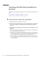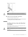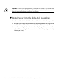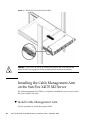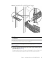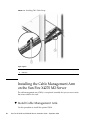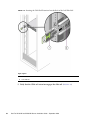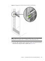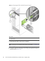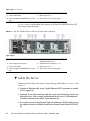
1
Sun Fire X4170 M2 and
X4270 M2 Servers
Installation Guide
Part No. 821-0481-13
September 2010, Revision A
Copyright © 2010 Oracle and/or its affiliates. All rights reserved.
This software and related documentation are provided under a license agreement containing restrictions on use and disclosure and are protected by
intellectual property laws. Except as expressly permitted in your license agreement or allowed by law, you may not use, copy, reproduce, translate,
broadcast, modify, license, transmit, distribute, exhibit, perform, publish, or display any part, in any form, or by any means. Reverse engineering,
disassembly, or decompilation of this software, unless required by law for interoperability, is prohibited.
The information contained herein is subject to change without notice and is not warranted to be error-free. If you find any errors, please report them to us
in writing.
If this is software or related software documentation that is delivered to the U.S. Government or anyone licensing it on behalf of the U.S. Government, the
following notice is applicable:
U.S. GOVERNMENT RIGHTS Programs, software, databases, and related documentation and technical data delivered to U.S. Government customers are
"commercial computer software" or "commercial technical data" pursuant to the applicable Federal Acquisition Regulation and agency-specific
supplemental regulations. As such, the use, duplication, disclosure, modification, and adaptation shall be subject to the restrictions and license terms set
forth in the applicable Government contract, and, to the extent applicable by the terms of the Government contract, the additional rights set forth in FAR
52.227-19, Commercial Computer Software License (December 2007). Oracle USA, Inc., 500 Oracle Parkway, Redwood City, CA 94065.
This software or hardware is developed for general use in a variety of information management applications. It is not developed or intended for use in any
inherently dangerous applications, including applications which may create a risk of personal injury. If you use this software or hardware in dangerous
applications, then you shall be responsible to take all appropriate fail-safe, backup, redundancy, and other measures to ensure the safe use. Oracle
Corporation and its affiliates disclaim any liability for any damages caused by use of this software or hardware in dangerous applications.
Oracle and Java are registered trademarks of Oracle and/or its affiliates. Other names may be trademarks of their respective owners.
AMD, Opteron, the AMD logo, and the AMD Opteron logo are trademarks or registered trademarks of Advanced Micro Devices. Intel and Intel Xeon are
trademarks or registered trademarks of Intel Corporation. All SPARC trademarks are used under license and are trademarks or registered trademarks of
SPARC International, Inc. UNIX is a registered trademark licensed through X/Open Company, Ltd.
This software or hardware and documentation may provide access to or information on content, products, and services from third parties. Oracle
Corporation and its affiliates are not responsible for and expressly disclaim all warranties of any kind with respect to third-party content, products, and
services. Oracle Corporation and its affiliates will not be responsible for any loss, costs, or damages incurred due to your access to or use of third-party
content, products, or services.
Copyright © 2010, Oracle et/ou ses affiliés. Tous droits réservés.
Ce logiciel et la documentation qui l’accompagne sont protégés par les lois sur la propriété intellectuelle. Ils sont concédés sous licence et soumis à des
restrictions d’utilisation et de divulgation. Sauf disposition de votre contrat de licence ou de la loi, vous ne pouvez pas copier, reproduire, traduire,
diffuser, modifier, breveter, transmettre, distribuer, exposer, exécuter, publier ou afficher le logiciel, même partiellement, sous quelque forme et par
quelque procédé que ce soit. Par ailleurs, il est interdit de procéder à toute ingénierie inverse du logiciel, de le désassembler ou de le décompiler, excepté à
des fins d’interopérabilité avec des logiciels tiers ou tel que prescrit par la loi.
Les informations fournies dans ce document sont susceptibles de modification sans préavis. Par ailleurs, Oracle Corporation ne garantit pas qu’elles
soient exemptes d’erreurs et vous invite, le cas échéant, à lui en faire part par écrit.
Si ce logiciel, ou la documentation qui l’accompagne, est concédé sous licence au Gouvernement des Etats-Unis, ou à toute entité qui délivre la licence de
ce logiciel ou l’utilise pour le compte du Gouvernement des Etats-Unis, la notice suivante s’applique :
U.S. GOVERNMENT RIGHTS. Programs, software, databases, and related documentation and technical data delivered to U.S. Government customers
are "commercial computer software" or "commercial technical data" pursuant to the applicable Federal Acquisition Regulation and agency-specific
supplemental regulations. As such, the use, duplication, disclosure, modification, and adaptation shall be subject to the restrictions and license terms set
forth in the applicable Government contract, and, to the extent applicable by the terms of the Government contract, the additional rights set forth in FAR
52.227-19, Commercial Computer Software License (December 2007). Oracle America, Inc., 500 Oracle Parkway, Redwood City, CA 94065.
Ce logiciel ou matériel a été développé pour un usage général dans le cadre d’applications de gestion des informations. Ce logiciel ou matériel n’est pas
conçu ni n’est destiné à être utilisé dans des applications à risque, notamment dans des applications pouvant causer des dommages corporels. Si vous
utilisez ce logiciel ou matériel dans le cadre d’applications dangereuses, il est de votre responsabilité de prendre toutes les mesures de secours, de
sauvegarde, de redondance et autres mesures nécessaires à son utilisation dans des conditions optimales de sécurité. Oracle Corporation et ses affiliés
déclinent toute responsabilité quant aux dommages causés par l’utilisation de ce logiciel ou matériel pour ce type d’applications.
Oracle et Java sont des marques déposées d’Oracle Corporation et/ou de ses affiliés.Tout autre nom mentionné peut correspondre à des marques
appartenant à d’autres propriétaires qu’Oracle.
AMD, Opteron, le logo AMD et le logo AMD Opteron sont des marques ou des marques déposées d’Advanced Micro Devices. Intel et Intel Xeon sont des
marques ou des marques déposées d’Intel Corporation. Toutes les marques SPARC sont utilisées sous licence et sont des marques ou des marques
déposées de SPARC International, Inc. UNIX est une marque déposée concédée sous licence par X/Open Company, Ltd.
Ce logiciel ou matériel et la documentation qui l’accompagne peuvent fournir des informations ou des liens donnant accès à des contenus, des produits et
des services émanant de tiers. Oracle Corporation et ses affiliés déclinent toute responsabilité ou garantie expresse quant aux contenus, produits ou
services émanant de tiers. En aucun cas, Oracle Corporation et ses affiliés ne sauraient être tenus pour responsables des pertes subies, des coûts
occasionnés ou des dommages causés par l’accès à des contenus, produits ou services tiers, ou à leur utilisation.
Please
Recycle
Contents
Using This Documentation
1.
vii
Preparing to Install the Sun Fire X4170 M2 and X4270 M2 Servers
Tools and Equipment Needed
1
Server Installation Task Checklist
Opening the Box
Unpacking
2
2
3
Package Contents Inventory
Options
4
ESD Precautions
4
Server Description
3
4
Front Panel Features
Back Panel
1
5
7
Server Supported Components
10
Sun Fire X4170 M2 Server Supported Components
11
Sun Fire X4270 M2 Server Supported Components
12
Server Specifications
13
Physical Specifications
Electrical Specifications
13
13
Environmental Requirements
15
iii
2.
Installing the Server Into a Rack With Slide-Rails
Before You Begin
17
Server Installation Process Overview
Rail Assemblies
Service Label
Rack Compatibility
18
18
18
19
Disassembling Slide-Rails
20
▼
Disassemble Bolt-On Slide-Rails
▼
Disassemble Tool-less Slide-Rails
20
21
Installing the Mounting Brackets Onto the Server
▼
17
Install Mounting Brackets
22
22
Attaching the Slide-Rail Assemblies to the Rack
24
▼
Attach Bolt-On Slide-Rail Assemblies
24
▼
Attach Tool-less Slide-Rail Assemblies
27
Installing the Server Into the Slide-Rail Assemblies
▼
27
Install Server Into the Slide-Rail Assemblies
28
Installing the Cable Management Arm on the Sun Fire X4170 M2 Server
▼
Install Cable Management Arm
30
Installing the Cable Management Arm on the Sun Fire X4270 M2 Server
▼
Install Cable Management Arm
37
Verifying Operation of the Slide-Rails and CMA
▼
3.
Verify Operation of Slide-Rails and CMA
Setting Up the Server
45
Connecting the Cables
45
▼
Cable the Server
44
44
46
Applying Standby Power for Initial SP Configuration
▼
Apply Standby Power to the Server
47
47
Applying Main Power to the Server for the First Time
iv
30
Sun Fire X4170 M2 and X4270 M2 Servers Installation Guide • September 2010
48
36
▼
Apply Main Power to the Server
48
Powering Off the Server From Main Power
▼
4.
Power Off from Main Power
Setting Up ILOM
Logging In to ILOM
52
53
About ILOM SP Interfaces
53
▼
Log In to ILOM Using a Serial Connection
▼
Log In to ILOM From an Ethernet Connection Using the CLI
Configuring an IP Address
▼
View or Assign the ILOM SP IP Address Using the ILOM CLI
58
58
Setting Up the Operating System
61
61
Supported Operating Systems
Installation Worksheet
62
63
Configuring the Preinstalled Operating System
Configuring the Preinstalled
Solaris 10 Operating System
Before You Begin
57
58
Log Out of ILOM Using the CLI
Before You Begin
54
55
View or Assign the ILOM SP IP Address Using the BIOS Setup
Utility 56
Managing Your Server
6.
53
▼
Logging Out of ILOM
5.
49
51
IP Configuration Task Checklist
▼
49
66
67
67
Configuring Server RAID Drives
68
Configuring the Preinstalled Solaris 10 Operating System
▼
Accessing the System Over the Network
▼
Accessing the System Locally
68
69
70
Contents
v
▼
Configure the Preinstalled Solaris 10 OS
▼
(Optional) Redirect the Console Output to the Video Port
▼
(Optional) Modify the GRUB Menu to Auto Boot
Solaris 10 Operating System User Information
Solaris 10 User Documentation
74
Reinstalling the Solaris Operating System
74
Download the Solaris Operating System
If You Need Help
77
Locate the Server Serial Number
vi
75
77
Setup Troubleshooting
Index
73
73
Using the Solaris Installation Program
7.
71
79
81
Sun Fire X4170 M2 and X4270 M2 Servers Installation Guide • September 2010
73
72
Using This Documentation
This guide contains hardware installation procedures and configuration procedures
for the preinstalled Oracle Solaris Operating System. You perform these procedures
to bring the server to a configurable and usable state.
This document is intended for system administrators, network administrators, and
service technicians who have an understanding of server systems.
■
“Product Information” on page vii
■
“Related Documentation” on page viii
■
“Documentation, Support, and Training” on page ix
■
“Documentation Feedback” on page x
■
“Product Downloads” on page x
Product Information
For information about Sun Fire X4170 M2 and X4270 M2 Servers, go to the following
web sites:
■
(http://www.oracle.com/goto/x4170m2)
■
(http://www.oracle.com/goto/x4270m2)
At these sites, you can find links and navigate to the following information and
downloads:
■
Product information and specifications
■
Supported operating systems
■
Software and firmware downloads
■
Supported option cards
vii
■
External storage options
■
Power calculator
Related Documentation
The related documents listed in the following table are available online at:
(http://docs.sun.com/app/docs/prod/sf.x4170m2#hic) and
(http://docs.sun.com/app/docs/prod/sf.x4270m2#hic)
viii
Title
Content
Part Number
Format
Sun Fire X4170 M2 and X4270
M2 Servers Product Notes
Late-breaking information
about the server
821-0482
PDF
HTML
Sun Fire X4170 M2 and X4270
M2 Servers Getting Started
Guide
Basic installation information
for setting up the server
821-0480
PDF
Print
Sun Fire X4170 M2 and X4270
M2 Servers Installation Guide
Detailed installation
information for setting up the
server
821-0481
PDF
HTML
Print option
Sun Fire X4170 M2 and X4270
M2 Servers Installation Guide
for Linux, Virtual Machine
Software, and Oracle Solaris
Operating Systems
Installation instructions for
the Linux, Oracle VM,
VMware, and Oracle Solaris
operating systems
821-0483
PDF
HTML
Sun Fire X4170 M2 and X4270
M2 Servers Installation Guide
for Windows Operating Systems
Installation instructions for
the Windows Server
operating systems
821-0484
PDF
HTML
Sun Installation Assistant 2.3
through 2.4 User’s Guide for
x64 Servers
Instructions for using the
Sun Installation Assistant to
install the Windows and
Linux operating systems
821-0694
PDF
HTML
Sun Fire X4170 M2 Server
Service Manual
Information and procedures
for maintaining and
upgrading the Sun Fire X4170
M2 Server
821-0486
PDF
HTML
Sun Fire X4270 M2 Server
Service Manual
Information and procedures
for maintaining and
upgrading the Sun Fire X4270
M2 Server
821-0488
PDF
HTML
Sun Fire X4170 M2 and X4270 M2 Servers Installation Guide • September 2010
Title
Content
Part Number
Format
Oracle x86 Servers Diagnostics
Guide
Information for diagnosing
and troubleshooting the
server
820-6750
PDF
HTML
Sun Server CLI Tools and
IPMItool 2.0 User’s Guide
Information for using
applications and utilities
common to x86 servers
821-1600
PDF
HTML
Oracle Integrated Lights Out
Manager (ILOM) 3.0
Documentation Collection
(formerly called Sun
Integrated Lights Out
Manager Documentation
Collection)
Documents covering ILOM
features and tasks that are
common to servers and
server modules that support
ILOM 3.0
820-5523
820-6410
820-6411
820-6412
820-6413
PDF
HTML
Oracle Integrated Lights Out
Manager (ILOM) 3.0
Supplement for Sun Fire X4170
M2 and X4270 M2 Servers
ILOM 3.0 information that is
specific to the Sun Fire X4170
M2 and X4270 M2 Servers
821-0489
PDF
HTML
Sun Fire X4170 M2 and X4270
M2 Servers Safety and
Compliance Guide
Hardware safety and
compliance information for
the server
821-0490
PDF
Important Safety Information
for Sun Hardware Systems
Multilingual hardware safety
and compliance information
for all Sun hardware system
821-1590
Print
Translated versions of some of these documents are available at the web sites listed
above this table. English documentation is revised more frequently and might be
more up-to-date than the translated documentation.
Documentation, Support, and Training
■
Documentation: (http://docs.sun.com)
■
Support: (http://www.sun.com/support/)
■
Training: (http://www.sun.com/training/)
Using This Documentation
ix
Documentation Feedback
Submit comments about this document by clicking the Feedback[+] link at:
(http://docs.sun.com)
Include the title and part number of your document with your feedback:
Sun Fire X4170 M2 and X4270 M2 Servers Installation Guide, part number 821-0481-13.
Product Downloads
To download the latest product software, go to one of the following web sites:
■
(http://www.oracle.com/goto/x4170m2)
■
(http://www.oracle.com/goto/x4270m2)
At these sites, you can find links and navigate to the following items:
x
■
Tools and Drivers DVD image
■
Sun Installation Assistant DVD image
■
Sun Validation Test Suite (SunVTS) Update
Sun Fire X4170 M2 and X4270 M2 Servers Installation Guide • September 2010
CHAPTER
1
Preparing to Install the Sun Fire
X4170 M2 and X4270 M2 Servers
This chapter describes Oracle’s Sun Fire X4170 M2 and X4270 M2 Servers hardware
and the information you need to know before you begin to install the servers into a
rack. It includes the following topics:
■
“Tools and Equipment Needed” on page 1
■
“Server Installation Task Checklist” on page 2
■
“Opening the Box” on page 2
■
“Server Description” on page 4
■
“Server Supported Components” on page 10
■
“Server Specifications” on page 13
Tools and Equipment Needed
To install the system, you need the following tools:
■
No. 2 Phillips screwdriver
■
ESD mat and grounding strap
■
Pencil, stylus, or other pointed device, for pushing front panel buttons
You also need a system console device, such as one of the following:
■
Sun workstation
■
ASCII terminal
■
Terminal server
■
Patch panel connected to a terminal server
1
Server Installation Task Checklist
TABLE 1-1 summarizes an ordered list of tasks that you must perform to properly
install the server.
TABLE 1-1
Step
Installation Task Checklist
Task Description
For Instructions, See:
1
Unpack the server and any optional
components ordered for the server from
the shipping containers.
• “Opening the Box” on page 2
2
If applicable, install optional server
components prior to installing the server
into the rack.
• Sun Fire X4170 M2 Server Service
Manual (821-0486)
• Sun Fire X4270 M2 Server Service
Manual (821-0488)
3
Install the server into a rack.
• Chapter 2
4
Connect cables to the server and apply
power to the server.
• Chapter 3
5
Configure the ILOM service processor.
• Chapter 4
6
If ordered, configure the factory-installed • Chapter 5
Solaris Operating System image shipped • Chapter 6
on one of the storage drives.
If applicable, install one of the following
operating systems:
• Oracle Enterprise Linux (OEL)
• Red Hat Enterprise Linux (RHEL)
• SUSE Linux Enterprise Server (SLES)
• Oracle Solaris 10 Operating System
• Oracle VM (OVM)
• VMware ESX/ESXi
• Microsoft Windows Server 2008 or
2008 R2 Operating Systems
• Sun Fire X4170 M2 and X4270 M2
Servers Installation Guide for Linux,
Virtual Machine Software, and Oracle
Solaris Operating Systems (821-0483)
• Sun Fire X4170 M2 and X4270 M2
Servers Installation Guide for Windows
Operating Systems (821-0484)
Opening the Box
Carefully open the shipping box.
2
Sun Fire X4170 M2 and X4270 M2 Servers Installation Guide • September 2010
Unpacking
Unpack all server components from the packing cartons. FIGURE 1-1 shows the
packing contents:
FIGURE 1-1
Unpacking the Box
Package Contents Inventory
The following items should be packaged with the Sun Fire X4170 M2 and X4270 M2
Servers:
■
Sun Fire 4170 M2 or X4270 M2 Server
■
Power cord, packaged separately with country kit
Chapter 1
Preparing to Install the Sun Fire X4170 M2 and X4270 M2 Servers
3
■
■
(Optional) Sun Fire X4170 M2 and X4270 M2 Servers Documentation and Media
Kit, including the following:
■
Sun Fire X4170 M2 and X4270 M2 Servers Installation Guide (this document)
■
License and safety documentation
■
Tools and Drivers DVD (includes drivers and additional software), Sun
Installation Assistant (SIA) CD, and SunVTS CD
(Optional) Rackmount kit containing rack rails and installation instructions
Options
Power cables are packaged separately from the other items.
Standard server components are installed at the factory. However, ordered options
such as additional memory or PCI Express cards are shipped separately. If possible,
install optional components before installing the server in a rack. For instructions for
installing server options, see the Sun Fire X4170 M2 Server Service Manual (821-0486)
or the Sun Fire X4270 M2 Server Service Manual (821-0488).
ESD Precautions
Electronic equipment is susceptible to damage by static electricity. Use a grounded
antistatic wrist strap, foot strap, or equivalent safety equipment to prevent
electrostatic damage (ESD) when you install or service the server.
Caution – To protect electronic components from electrostatic damage, which can
permanently disable the system or require repair by Oracle service technicians, place
components on an antistatic surface, such as an antistatic discharge mat, an antistatic
bag, or a disposable antistatic mat. Wear an antistatic grounding strap connected to
a metal surface on the chassis when you work on system components.
Server Description
This section shows the front and back of the Sun Fire X4170 M2 and X4270 M2
Servers.
4
Sun Fire X4170 M2 and X4270 M2 Servers Installation Guide • September 2010
Front Panel Features
FIGURE 1-2 shows the Sun Fire X4170 M2 Server front panel and describes its
components.
FIGURE 1-2
Sun Fire X4170 M2 Server Front Panel
Figure Legend
1
Product Serial Number (PSN) label and Radio
Frequency Identification (RFID) tag
10 Hard disk drive 4 (optional)
2
Locator LED/Locator button: white
11 Hard disk drive 5 (optional)
3
Service Action Required LED: amber
12 DVD drive (optional)
4
Power/OK LED: green
13 Hard disk drive 6 (optional)
5
Power button
14 Hard disk drive 7 (optional)
6
Hard disk drive 1 (optional)
15 USB 2.0 ports (2)
7
Hard disk drive 0 (optional)
16 Disk configuration label
8
Hard disk drive 3 (optional)
17 Power Supply Service Action Required LED:
amber
System Overtemperature LED: amber
Fan Module Service Action Required LED:
amber
9
Hard disk drive 2 (optional)
The Sun Fire X4270 M2 Server can optionally be configured with 12 or 24 storage
drives. FIGURE 1-3 shows the 12 storage drive configuration. FIGURE 1-4 shows the 24
storage drive configuration.
Note – In
FIGURE 1-4, the storage drives are numbered 0 to 23 from left to right.
Chapter 1
Preparing to Install the Sun Fire X4170 M2 and X4270 M2 Servers
5
FIGURE 1-3
Sun Fire X4270 M2 Server Front Panel (With 12 Storage Drives)
Figure Legend
1
Product Serial Number (PSN) label and Radio
Frequency Identification (RFID) tag
12 Hard disk drive 6 (optional)
2
Power button
13 Hard disk drive 7 (optional)
3
Locator LED/Locator button: white
14 Hard disk drive 8 (optional)
4
Service Action Required LED (System Level):
amber
15 Hard disk drive 9 (optional)
5
Power/OK LED: green
16 Hard disk drive 10 (optional)
6
Hard disk drive 2 (optional)
17 Hard disk drive 11 (optional)
7
Hard disk drive 1 (optional)
18 Fan Module Service Action Required LED:
amber
8
Hard disk drive 0 (optional)
19 Power Supply Service Action Required LED:
amber
9
Hard disk drive 3 (optional)
20 System Overtemperature LED: amber
10 Hard disk drive 4 (optional)
21 USB 2.0 ports (2)
11 Hard disk drive 5 (optional)
22
6
Disk configuration label
Sun Fire X4170 M2 and X4270 M2 Servers Installation Guide • September 2010
FIGURE 1-4
Sun Fire X4270 M2 Server Front Panel (With 24 Storage Drives)
Figure Legend
1
Product Serial Number (PSN) label and Radio
Frequency Identification (RFID) tab
6
Fan Module Service Action Required LED: amber
2
Power button
7
Power Supply Service Action Required LED: amber
3
Locator LED/Locator button: white
8
System Overtemperature LED: amber
4
Service Action Required LED (System Level):
amber
9
USB 2.0 ports (2)
5
Power/OK LED: green
10 Disk configuration label
Back Panel
FIGURE 1-5 shows the Sun Fire X4170 M2 Server back panel and describes its
components.
Chapter 1
Preparing to Install the Sun Fire X4170 M2 and X4270 M2 Servers
7
FIGURE 1-5
Sun Fire X4170 M2 Server Back Panel
Figure Legend
1
Power supply unit 0 connector
8
PCI Express Module slot (2)
2
Power supply unit 0 status indicator LEDs:
Power Supply OK: green
Power Supply Fail: amber
AC OK: green
9
Serial management (SER MGT)/RJ-45 serial
port
3
Power supply unit 1 connector
10 Service processor (SP) network management
(NET MGT) port
4
Power supply unit 1 status indicator LEDs:
Power Supply OK: green
Power Supply Fail: amber
AC OK: green
11 Gigabit Ethernet ports NET 0, 1, 2, 3
5
System status LEDs:
Power: green
Attention: amber
Locate: white
12 USB 2.0 ports (0, 1)
6
PCI Express Module slot (0)
13 HD15 video connector (analog VGA)
7
PCI Express Module slot (1)
FIGURE 1-6 shows the Sun Fire X4270 M2 Server back panel without rear mounted
storage drives. FIGURE 1-7 shows the Sun Fire X4270 M2 Server back panel with rear
mounted storage drives.
8
Sun Fire X4170 M2 and X4270 M2 Servers Installation Guide • September 2010
FIGURE 1-6
Sun Fire X4270 M2 Server Back Panel (Without Rear Boot Drives)
Figure Legend
1
Power supply unit 1 (PSU1)
8
PCI Express Module slot (5) (filler panel
shown)
2
Power supply unit 0 (PSU0)
9
System status LEDs:
Power: green
Attention: amber
Locate: white
3
PCI Express Module slot (0) (filler panel shown)
10 Serial management (SER MGT)/RJ-45 serial
port
4
PCI Express Module slot (3) (filler panel shown)
11 Service processor (SP) network management
(NET MGT) port
5
PCI Express Module slot (1) (filler panel shown)
12 Gigabit Ethernet ports NET 0, 1, 2, 3
6
PCI Express Module slot (4) (filler panel shown)
13 USB 2.0 ports (0, 1)
7
PCI Express Module slot (2) (filler panel shown)
14 HD15 video connector (analog VGA)
Chapter 1
Preparing to Install the Sun Fire X4170 M2 and X4270 M2 Servers
9
FIGURE 1-7
Back Panel of Sun Fire X4270 M2 Server Back Panel (With Rear Boot Drives)
Figure Legend
1
Power supply unit 1 (PSU1)
8
Boot disk drive 0
2
Power supply unit 0 (PSU0)
9
System status LEDs:
Power: green
Attention: amber
Locate: white
3
PCIe Slot 0 (filler panel shown)
10
Serial management (SER MGT)/RJ-45 serial port
4
PCIe Slot 3 (filler panel shown)
11
Service processor (SP) network management
(NET MGT) port
5
PCIe Slot 1 (filler panel shown)
12
Gigabit Ethernet ports NET 0, 1, 2, 3
6
PCIe Slot 4 (filler panel shown)
13
USB 2.0 ports (0, 1)
7
Boot disk drive 1
14
HD15 video connector (analog VGA)
Server Supported Components
This section describes the components that are supported in the Sun Fire X4170 M2
and X4270 M2 Servers.
10
Sun Fire X4170 M2 and X4270 M2 Servers Installation Guide • September 2010
Sun Fire X4170 M2 Server Supported Components
The following table describes the components and capabilities of the Sun Fire X4170
M2 Server.
TABLE 1-2
Sun Fire X4170 M2 Server Components
Component
Sun Fire X4170 M2 Server
CPU
One or two quad-core (2.4-GHz) or six-core (2.26-GHz or 2.93-GHz) processors
with three integrated DDR3 memory controllers per processor. The following
CPUs are supported:
• 95 Watts
• 80 Watts
• 60 Watts
Memory
Nine DDR3 DIMMs per processor for a maximum of 18 DDR3 DIMMs and a
maximum of 144 GB of memory
Storage devices
• Up to six 2.5-inch SATA hard drive devices (HDDs) or four solid-state drives
(SSDs)
• Up to eight 2.5-inch SAS/SATA HDDs or four SSDs with the optional Hardware
RAID controller
• DVD-RW drive
USB ports
Two front, two rear, and one internal (for a USB thumb drive)
PCI Express 2.0 I/O slots
Three low-profile PCIe Gen2 slots (one x16 and two x8)
PCI Express I/O cards
For a list of I/O cards that are customer-orderable options, go to the following
web site and navigate to the appropriate page:
(http://www.oracle.com/goto/x4170m2)
Ethernet ports
Four Gigabit Ethernet (GbE) ports on rear panel
Each Network Interface Card (NIC) supports I/O Acceleration Technology 3
(IOAT3)
Service processor (SP)
Uses the SP subsystem
Includes the Baseboard Management Controller (BMC), which supports the
industry-standard IPMI feature set
Supports remote KVMS over IP
Includes serial port
Supports Ethernet access to SP through a dedicated 10/100BaseT management
port and optionally through one of the host GbE ports (sideband management)
Power supplies
Up to two hot-pluggable power supplies
Cooling fans
Redundant hot-pluggable fans
Management software
Oracle Integrated Lights Out Manager 3.0
Chapter 1
Preparing to Install the Sun Fire X4170 M2 and X4270 M2 Servers
11
Sun Fire X4270 M2 Server Supported Components
The following table describes the components and capabilities of the Sun Fire X4270
M2 Server.
TABLE 1-3
Sun Fire X4270 M2 Server Components and Capabilities
Component
Sun Fire X4270 M2 Server
CPU
One or two quad-core (2.4-GHz) or six-core (2.93-GHz or 3.33-GHz) processors
with three integrated DDR3 memory controllers per processor. The following
CPUs are supported:
• 130 Watts
• 95 Watts
• 80 Watts
Memory
Nine DDR3 DIMMs per processor for a maximum of 18 DDR3 DIMMs and a
maximum of 144 GB of memory
Storage devices
• Up to twelve 3.5-inch SAS/SATA HDDs with the optional Hardware RAID
controller
• Up to twenty-four 2.5-inch SAS/SATA HDDs with the optional Hardware RAID
controller
• Up to two optional rear-located (using PCIe slots 2 and 5) 2.5-inch SATA HDDs.
These disks are for boot purposes only.
USB ports
Two front, two rear, and one internal (for a USB thumb drive)
PCI Express 2.0 I/O slots
Six x8 low-profile PCIe Gen2 slots
PCI Express I/O cards
For a list of I/O cards that are customer-orderable options, go to the following
web site and navigate to the appropriate page:
(http://www.oracle.com/goto/x4270m2)
Ethernet ports
Four Gigabit Ethernet (GbE) ports on rear panel
Each Network Interface Card (NIC) supports I/O Acceleration Technology 3
(IOAT3)
Service processor (SP)
Uses the SP subsystem
Includes the Baseboard Management Controller (BMC), which supports the
industry-standard IPMI feature set
Supports remote KVMS over IP
Includes a serial port
Supports Ethernet access to SP through a dedicated 10/100BaseT management
port and optionally through one of the host GbE ports (sideband management)
Power supplies
Up to two hot-pluggable power supplies
Cooling fans
Redundant hot-pluggable fans
Management software
Oracle Integrated Lights Out Manager 3.0
12
Sun Fire X4170 M2 and X4270 M2 Servers Installation Guide • September 2010
Server Specifications
Physical Specifications
TABLE 1-4 lists the physical specifications for the Sun Fire X4170 M2 and X4270 M2
Servers.
TABLE 1-4
Servers Physical Specifications
Parameter
Sun Fire X4170 M2 Server
Sun Fire X4270 M2 Server
Height
1.71 inches/43.43 mm
3.43 inches/87.12 mm
Width
16.75 inches/425.45 mm
16.75 inches/425.45 mm
Depth
27.0 inches/685.8 mm
30.0 inches/762.0 mm
Weight
36 lbs/16.36 kg
65 lbs/29.54 kg
Electrical Specifications
TABLE 1-5 lists the electrical specifications for the Sun Fire X4170 M2 and X4270 M2
Servers.
Note – The power dissipation numbers listed in the following table are the
maximum rated power numbers for the power supply used in these servers. The
numbers are not a rating of the actual power consumption of the system. For up to
date information on power consumption, go to the following web sites and navigate
to the appropriate page: (http://www.oracle.com/goto/x4170m2) or
(http://www.oracle.com/goto/x4270m2).
TABLE 1-5
Servers Electrical Specifications
Parameter
Value
Sun Fire X4170 M2 Server
Input
Nominal frequencies
50/60 Hz
Nominal voltage range
100-120/200-240 VAC
Chapter 1
Preparing to Install the Sun Fire X4170 M2 and X4270 M2 Servers
13
TABLE 1-5
Servers Electrical Specifications (Continued)
Parameter
Value
Maximum current AC RMS
9.0 amps Max
AC operating range
90-264 VAC
Output
3.3 VDC STBY
3.6A
+12 VDC
62.3 A
Power dissipation
Max power consumption
873 W
Max heat output
2977 BTU/hr
Volt-Ampere rating
891 VA @ 240 VAC, 0.98 P.F.
Sun Fire X4270 M2 Server
Input
Nominal frequencies
50/60 Hz
Nominal voltage range
100 VAC, 110-127 VAC, 200-240 VAC
Maximum current AC RMS
13.0 amps Max
AC operating range
90-264 VAC
Output
3.3 VDC STBY
3.0 A
+12 VDC
86.7 A
Power dissipation
14
Max power consumption
1235.3 W
Max heat output
4212 BTU/hr
Volt-Ampere rating
1261 VA @ 240 VAC, 0.98 P.F.
Sun Fire X4170 M2 and X4270 M2 Servers Installation Guide • September 2010
Environmental Requirements
TABLE 1-6 lists the environmental requirements for the Sun Fire X4170 M2 and X4270
M2 Servers.
TABLE 1-6
Servers Environmental Requirements
Parameter
Value
Operating temperature
(single, non-rack system)
5° C to 35° C (41° F to 95° F)
Non-operating temperature
(single, non-rack system)
-40° C to 70° C (-40° F to 158° F)
Operating humidity (single, 10% to 90% relative humidity, non-condensing
non-rack system)
Non-operating humidity
(single, non-rack system)
Up to 93% relative humidity, non-condensing
Altitude (operating) (single, • For the Sun Fire X4170
non-rack system)
ambient temperature is
above 900 m
• For the Sun Fire X4270
ambient temperature is
above 900 m
Altitude (non-operating)
(single, non-rack system)
Chapter 1
M2 Server: Up to 3000 m, maximum
derated by 1 degree C per 300 m
M2 Server: Up to 3048 m, maximum
derated by 1 degree C per 300 m
Up to 12,000 m
Preparing to Install the Sun Fire X4170 M2 and X4270 M2 Servers
15
16
Sun Fire X4170 M2 and X4270 M2 Servers Installation Guide • September 2010
CHAPTER
2
Installing the Server Into a Rack
With Slide-Rails
This chapter describes how to place the server into a rack using the rail assembly in
the rackmount kit. Perform these procedures if the rail assembly is purchased.
This chapter includes the following topics:
■
“Before You Begin” on page 17
■
“Rack Compatibility” on page 19
■
“Disassembling Slide-Rails” on page 20
■
“Installing the Mounting Brackets Onto the Server” on page 22
■
“Attaching the Slide-Rail Assemblies to the Rack” on page 24
■
“Installing the Server Into the Slide-Rail Assemblies” on page 27
■
“Installing the Cable Management Arm on the Sun Fire X4170 M2 Server” on
page 30
■
“Installing the Cable Management Arm on the Sun Fire X4270 M2 Server” on
page 36
■
“Verifying Operation of the Slide-Rails and CMA” on page 44
Note – In this guide, the term rack means either an open rack or a closed cabinet.
Before You Begin
Read the following overview and see the service label on the top cover before you
begin to install the server into a rack.
17
Server Installation Process Overview
To install your server into a four-post rack using the slide-rail and cable
management arm options, see the following sections to perform the tasks in the
order listed.
1. “Rack Compatibility” on page 19
2. “Disassembling Slide-Rails” on page 20
3. “Installing the Mounting Brackets Onto the Server” on page 22
4. “Installing the Cable Management Arm on the Sun Fire X4170 M2 Server” on
page 30 or “Installing the Cable Management Arm on the Sun Fire X4270 M2
Server” on page 36
5. “Verifying Operation of the Slide-Rails and CMA” on page 44
6. “Connecting the Cables” on page 45
Rail Assemblies
The server might include either tool-less or bolt-on rail assemblies in rackmount kits.
Instructions for both types are included in this chapter.
Service Label
Refer to the service label on the server top cover for instructions on how to install
your server into a four-post rack, using the slide-rail and cable management arm
options. The service label includes instructions for both tool-less and bolt-on rail
assemblies.
18
Sun Fire X4170 M2 and X4270 M2 Servers Installation Guide • September 2010
Rack Compatibility
Check that your rack is compatible with the slide-rail and cable management arm
(CMA) options. The optional slide-rails are compatible with a wide range of
equipment racks that meet the following standards.
TABLE 2-1
Rack Compatibility
Item
Requirement
Structure
Four-post rack (mounting at both front and rear).
Two-post racks are not compatible.
Rack horizontal opening and unit
vertical pitch
Conforms to ANSI/EIA 310-D-1992 or IEC 60927
standards.
Distance between front and rear
mounting planes
Minimum 610 mm and maximum 915 mm
(24 inches to 36 inches).
Clearance depth in front of front
mounting plane
Distance to front cabinet door is at least 25.4 mm
(1 inch).
Clearance depth behind front
mounting plane
Distance to rear cabinet door is at least 800 mm (31.5
inches) with the cable management arm, or 700 mm
(27.5 inches) without the cable management arm.
Clearance width between front and
rear mounting planes
Distance between structural supports and cable
troughs is at least 456 mm (18 inches).
Server dimensions
Depth: (not including PSU handle): 685.80 mm (27.0
inches)
Width: (not including ears): 425.45 mm (16.75 inches)
Height: Sun Fire X4170 M2 Server: 43.43 mm (1.71
inches), Sun Fire X4270 M2 Server: 87.12 mm (3.43
inches)
Caution – Always load equipment into a rack from the bottom up so that the rack
will not become top-heavy and tip over. Deploy your rack’s anti-tip bar to prevent
the rack from tipping during equipment installation.
Caution – Elevated Operating Ambient Temperature: If the server is installed in a
closed or multi-unit rack assembly, the operating ambient temperature of the rack
environment might be greater than room ambient temperature. Therefore,
consideration should be given to installing the equipment in an environment
Chapter 2
Installing the Server Into a Rack With Slide-Rails
19
compatible with the maximum ambient temperature (Tma) specified for the server.
For server environmental requirements, see “Environmental Requirements” on
page 15.
Caution – Reduced Air Flow: Installation of the equipment in a rack should be
such that the amount of air flow required for safe operation of the equipment is not
compromised.
Caution – Mechanical Loading: Mounting of the equipment in the rack should be
such that a hazardous condition is not achieved due to uneven mechanical loading.
Caution – Circuit Overloading: Consideration should be given to the connection of
the equipment to the supply circuit and the effect that overloading of the circuits
might have on over-current protection and supply wiring. Appropriate
consideration of equipment nameplate power ratings should be used when
addressing this concern.
Caution – Reliable Earthing: Reliable earthing of rackmounted equipment should
be maintained. Particular attention should be given to supply connections other than
direct connections to the branch circuit (for example, use of power strips).
Caution – Slide-rail mounted equipment is not to be used as a shelf or a work
space.
Disassembling Slide-Rails
Complete one of the following procedures before installation:
■
“Disassemble Bolt-On Slide-Rails” on page 20
■
“Disassemble Tool-less Slide-Rails” on page 21
▼ Disassemble Bolt-On Slide-Rails
To remove the mounting brackets from the bolt-on slide-rail assemblies:
20
Sun Fire X4170 M2 and X4270 M2 Servers Installation Guide • September 2010
1. Unpack the slide-rails.
2. Locate the slide-rail lock at the front of one of the slide-rail assemblies
(FIGURE 2-1).
3. Squeeze and hold the tabs at the top and bottom of the lock while you pull the
mounting bracket out of the slide-rail assembly until it reaches the stop
(FIGURE 2-1).
4. Push the mounting bracket release button toward the front of the mounting
bracket (FIGURE 2-1), and simultaneously withdraw the mounting bracket from
the slide-rail assembly.
5. Repeat for the remaining slide-rail assembly.
FIGURE 2-1
Disassembling the Bolt-On Slide-Rail Before Installation
Figure Legend
1
Slide-rail lock
2
Mounting bracket release button
▼ Disassemble Tool-less Slide-Rails
To remove the mounting brackets from the tool-less slide-rail assemblies:
Chapter 2
Installing the Server Into a Rack With Slide-Rails
21
●
Refer to the installation card included with the rackmount kit for instructions
on removing the mounting brackets from the tool-less slide-rail assemblies.
Installing the Mounting Brackets Onto
the Server
You must install the mounting brackets onto the server before you can rackmount
the server.
▼ Install Mounting Brackets
To install the mounting brackets onto the sides of the server:
1. Position a mounting bracket against the chassis so that the slide-rail lock is at
the server front, and the four keyed openings on the mounting bracket are
aligned with the four locating pins on the side of the chassis (FIGURE 2-2).
22
Sun Fire X4170 M2 and X4270 M2 Servers Installation Guide • September 2010
FIGURE 2-2
Aligning the Mounting Bracket With the Server Chassis
Figure Legend
1
Chassis front
2
Slide-rail lock
3
Mounting bracket
4
Mounting bracket clip
2. With the heads of the four chassis locating pins protruding though the four
keyed openings in the mounting bracket, pull the mounting bracket toward the
front of the chassis until the mounting bracket clip locks into place with an
audible click (FIGURE 2-2).
3. Verify that the rear locating pin has engaged the mounting bracket clip
(FIGURE 2-2).
4. Repeat to install the remaining mounting bracket on the other side of the
server.
Chapter 2
Installing the Server Into a Rack With Slide-Rails
23
Attaching the Slide-Rail Assemblies to
the Rack
Complete one of the following procedures to attach the slide-rail assemblies to the
rack:
■
“Attach Bolt-On Slide-Rail Assemblies” on page 24
■
“Attach Tool-less Slide-Rail Assemblies” on page 27
▼ Attach Bolt-On Slide-Rail Assemblies
To attach bolt-on slide-rail assemblies to the rack:
1. Position a slide-rail assembly in your rack so that the brackets at each end of
the slide-rail assembly are on the outside of the front and rear rack posts
(FIGURE 2-3).
2. Attach the slide-rail assembly to the rack posts, but do not tighten the screws
completely.
Choose one of the following methods to attach the slide-rails. The method you
use varies, depending on the type of rack:
24
■
If your rack has threaded mounting holes in the rack posts, first determine
whether the threads are metric or standard, then insert the correct mounting
screws through the slide-rail brackets and into the threaded holes.
■
If your rack does not have threaded mounting holes, insert the mounting
screws through both the slide-rail brackets and rack posts, then secure them
with the caged nuts.
Sun Fire X4170 M2 and X4270 M2 Servers Installation Guide • September 2010
FIGURE 2-3
Attaching Slide-Rail Assembly to Rack Post
Figure Legend
1
Slide-rail assembly
2
Rack post
3
Slide-rail assembly bracket on outside of rack post
3. Repeat Step 1 and Step 2 for the remaining slide-rail assembly.
4. From the front of the rack, set the proper width of the rails using the spacer
(FIGURE 2-4).
Chapter 2
Installing the Server Into a Rack With Slide-Rails
25
FIGURE 2-4
Setting the Rail Width
Figure Legend
1
Rail-width spacer
2
Attaching the spacer to the rails
5. Tighten the screws on both brackets (FIGURE 2-4).
6. Remove the spacer and confirm that the rails are attached tightly to the rack.
7. Repeat Step 4 through Step 6 for the side-rail assembly at the rear of the rack.
8. If available, extend the anti-tip bar at the bottom of the rack (FIGURE 2-5).
26
Sun Fire X4170 M2 and X4270 M2 Servers Installation Guide • September 2010
FIGURE 2-5
Extending the Anti-tip Bar
Caution – If your rack does not have an anti-tip bar, the rack could tip over.
▼ Attach Tool-less Slide-Rail Assemblies
To attach tool-less slide-rail assemblies to the rack:
●
Refer to the installation card included with the rackmount kit for instructions
on attaching tool-less slide-rail assemblies to the rack.
Installing the Server Into the Slide-Rail
Assemblies
Use this procedure to install the server chassis, with mounting brackets, into the
slide-rail assemblies that are mounted to the rack.
Caution – This procedure requires a minimum of two people because of the weight
of the server. Attempting this procedure alone could result in equipment damage or
personal injury.
Chapter 2
Installing the Server Into a Rack With Slide-Rails
27
Caution – Always load equipment into a rack from the bottom up so that the rack
will not become top-heavy and tip over. Extend your rack’s anti-tip bar to prevent
the rack from tipping during equipment installation.
▼ Install Server Into the Slide-Rail Assemblies
1. Push the slide-rails into the slide-rail assemblies in the rack as far as possible.
2. Raise the server so that the rear ends of the mounting brackets are aligned with
the slide-rail assemblies that are mounted in the rack (FIGURE 2-6).
3. Insert the mounting brackets into the slide-rails, then push the server into the
rack until the mounting brackets encounter the slide-rail stops (approximately
12 inches, or 30 cm).
28
Sun Fire X4170 M2 and X4270 M2 Servers Installation Guide • September 2010
FIGURE 2-6
Inserting the Server With Mounting Brackets Into the Slide-Rails
Figure Legend
1
Inserting mounting bracket into slide rail
2
Slide-rail release button
3
Slide-rail lock
4. Simultaneously push and hold the slide-rail release buttons on each mounting
bracket while you push the server into the rack (FIGURE 2-6). Continue pushing
until the slide-rail locks (on the front of the mounting brackets) engage the
slide-rail assemblies (FIGURE 2-7).
You will hear an audible click.
Chapter 2
Installing the Server Into a Rack With Slide-Rails
29
FIGURE 2-7
Sliding the Server Back Into the Rack
Caution – Verify that the server is securely mounted in the rack and that the
slide-rail locks are engaged with the mounting brackets before continuing.
Installing the Cable Management Arm
on the Sun Fire X4170 M2 Server
The cable management arm (CMA) is an optional assembly that you can use to route
the server cables in the rack.
▼ Install Cable Management Arm
Use this procedure to install the optional CMA.
30
Sun Fire X4170 M2 and X4270 M2 Servers Installation Guide • September 2010
1. Unpack the CMA parts.
2. Take the CMA to the back of the equipment rack and ensure that you have
adequate room to work around the back of the server.
Note – References to “left” or “right” in this procedure assume that you are facing
the back of the equipment rack.
3. Remove tape to separate the parts of the CMA.
The CMA rail extension might be taped to the CMA arm.
4. Attach the CMA rail extension into the left slide-rail until the extension locks
into place with an audible click (FIGURE 2-8).
FIGURE 2-8
Inserting the CMA Rail Extension Into the Back of the Left Slide-Rail
Figure Legend
1
CMA rail extension
2
Left slide-rail
5. Verify that the CMA rail extension engages the slide-rail (FIGURE 2-9).
Chapter 2
Installing the Server Into a Rack With Slide-Rails
31
FIGURE 2-9
Engaging the CMA Rail Extension With the Left Slide-Rail
Note – Support the CMA in the remaining installation steps. Do not allow the arm
to hang by its own weight until it is secured by all three attachment points.
6. Insert the CMA’s mounting bracket connector into the right slide-rail until the
connector locks into place with an audible click (FIGURE 2-10).
32
Sun Fire X4170 M2 and X4270 M2 Servers Installation Guide • September 2010
FIGURE 2-10
Inserting the CMA Mounting Bracket Into the Back of the Right Slide-Rail
Figure Legend
1
CMA mounting bracket
2
Right slide-rail
7. Insert the right CMA slide-rail connector into the right slide-rail assembly until
the connector locks into place with an audible click (FIGURE 2-11).
Chapter 2
Installing the Server Into a Rack With Slide-Rails
33
FIGURE 2-11
Inserting CMA Slide-Rail Connector Into the Back of the Right Slide-Rail
Figure Legend
1
CMA slide-rail connector
2
Right slide-rail
8. Insert the left CMA slide-rail connector into the rail extension on the left
slide-rail assembly until the connector locks into place with an audible click
(FIGURE 2-12).
34
Sun Fire X4170 M2 and X4270 M2 Servers Installation Guide • September 2010
FIGURE 2-12
Connecting the CMA to the Rail Extension Connector
Figure Legend
1
CMA extension arm (on left slide-rail)
2
CMA extension
9. Install and route cables to your server, as required.
Note – Instructions for installing the server cables are provided in “Connecting the
Cables” on page 45.
10. Attach the cable hook and loop straps to the CMA, and press them into place to
secure the cables (FIGURE 2-13).
For best results, place three cable straps, evenly spaced, on the rear-facing side of
the CMA and three cable straps on the side of the CMA nearest the server.
Chapter 2
Installing the Server Into a Rack With Slide-Rails
35
FIGURE 2-13
Installing CMA Cable Straps
Figure Legend
1
CMA cable strap
2
CMA arm
Installing the Cable Management Arm
on the Sun Fire X4270 M2 Server
The cable management arm (CMA) is an optional assembly that you can use to route
the server cables in the rack.
▼ Install Cable Management Arm
Use this procedure to install the optional CMA.
36
Sun Fire X4170 M2 and X4270 M2 Servers Installation Guide • September 2010
1. Unpack the CMA parts.
2. Take the CMA to the back of the equipment rack and ensure that you have
adequate room to work around the back of the server.
Note – References to “left” or “right” in this procedure assume that you are facing
the back of the equipment rack.
3. Remove tape to separate the parts of the CMA.
The CMA rail extension might be taped to the CMA arm.
4. Attach the CMA rail extension into the left slide-rail until the extension locks
into place with an audible click (FIGURE 2-14).
Chapter 2
Installing the Server Into a Rack With Slide-Rails
37
FIGURE 2-14
Inserting the CMA Rail Extension Into the Back of the Left Slide-Rail
Figure Legend
1
CMA rail extension
2
Left slide-rail
5. Verify that the CMA rail extension engages the slide-rail (FIGURE 2-15).
38
Sun Fire X4170 M2 and X4270 M2 Servers Installation Guide • September 2010
FIGURE 2-15
Engaging the CMA Rail Extension With the Left Slide-Rail
Note – Support the CMA in the remaining installation steps. Do not allow the arm
to hang by its own weight until it is secured by all three attachment points.
6. Insert the CMA’s mounting bracket connector into the right slide-rail until the
connector locks into place with an audible click (FIGURE 2-16).
Chapter 2
Installing the Server Into a Rack With Slide-Rails
39
FIGURE 2-16
Inserting the CMA Mounting Bracket Into the Back of the Right Slide-Rail
Figure Legend
1
CMA mounting bracket
2
Right slide-rail
7. Insert the right CMA slide-rail connector into the right slide-rail assembly until
the connector locks into place with an audible click (FIGURE 2-17).
40
Sun Fire X4170 M2 and X4270 M2 Servers Installation Guide • September 2010
FIGURE 2-17
Inserting CMA Slide-Rail Connector Into the Back of the Right Slide-Rail
Figure Legend
1
CMA slide-rail connector
2
Right slide-rail
8. Insert the left CMA slide-rail connector into the rail extension on the left
slide-rail assembly until the connector locks into place with an audible click
(FIGURE 2-18).
Chapter 2
Installing the Server Into a Rack With Slide-Rails
41
FIGURE 2-18
Connecting the CMA to the Rail Extension Connector
Figure Legend
1
CMA extension arm (on left slide-rail)
2
CMA extension
9. Install and route cables to your server, as required.
Note – Instructions for installing the server cables are provided in “Connecting the
Cables” on page 45.
10. If required, attach the cable hangers to the CMA, and snap them into place to
secure the cables (FIGURE 2-19).
42
Sun Fire X4170 M2 and X4270 M2 Servers Installation Guide • September 2010
Note – Cable hangers are preinstalled on the CMA. Perform the procedure in this
step if you need to reinstall cable hangers on the CMA.
For best results, place three cable hangers, evenly spaced, on the rear-facing side
of the CMA and three cable hangers on the side of the CMA nearest the server.
FIGURE 2-19
Installing CMA Cable Hangers
Figure Legend
1
CMA cable hanger
2
CMA arm
Chapter 2
Installing the Server Into a Rack With Slide-Rails
43
Verifying Operation of the Slide-Rails
and CMA
Use the following procedure to ensure that the slide-rails and CMA are operating
correctly.
▼ Verify Operation of Slide-Rails and CMA
Note – Two people are recommended for this procedure: one to move the server in
and out of the rack, and one to observe the cables and CMA.
1. Slowly pull the server out of the rack until the slide-rails reach their stops.
2. Inspect the attached cables for any binding or kinks.
3. Verify that the CMA extends fully from the slide-rails.
4. Push the server back into the rack, as described in the following sub-steps.
When the server is fully extended, you must release two sets of slide-rail stops to
return the server to the rack:
a. The first set of stops are levers, located on the inside of each slide-rail, just
behind the back panel of the server. These levers are labeled “PUSH.” Push
in both levers simultaneously and slide the server toward the rack.
The server will slide in approximately 18 inches (46 cm) and stop.
Verify that the cables and the CMA retract without binding before you
continue.
b. The second set of stops are the slide-rail release buttons, located near the
front of each mounting bracket (FIGURE 2-7). Simultaneously push or pull
both of the slide-rail release buttons, and push the server completely into
the rack until both slide-rail locks engage.
5. Adjust the cable straps and CMA, as required.
44
Sun Fire X4170 M2 and X4270 M2 Servers Installation Guide • September 2010
3
CHAPTER
Setting Up the Server
This chapter describes how to connect cables and power on the server for the first
time. It includes the following topics:
■
“Connecting the Cables” on page 45
■
“Applying Standby Power for Initial SP Configuration” on page 47
■
“Applying Main Power to the Server for the First Time” on page 48
■
“Powering Off the Server From Main Power” on page 49
Connecting the Cables
Connect the power and device data cables to the server back panel. FIGURE 3-1 shows
and describes the locations of the Sun Fire X4170 M2 Server back panel connectors.
FIGURE 3-1
Sun Fire X4170 M2 Server M2 Server Back Panel Connectors
Figure Legend
1
Power supply unit 0 connector
5
Service processor (SP) network management
(NET MGT) Ethernet port
45
Figure Legend (Continued)
2
Power supply unit 1 connector
6
Gigabit Ethernet ports NET 0, 1, 2, 3
3
System status LEDs
7
USB 2.0 ports (0, 1)
4
Serial management (SER MGT)/RJ-45 serial
port
8
HD15 video connector (analog VGA)
FIGURE 3-2 shows and describes the locations of the Sun Fire X4270 M2 Server M2
Server back panel connectors.
FIGURE 3-2
Sun Fire X4270 M2 Server M2 Server Back Panel Connectors
Figure Legend
1
Power supply unit 1 connector
5
Service processor (SP) network management
(NET MGT) Ethernet port
2
Power supply unit 0 connector
6
Gigabit Ethernet ports NET 0, 1, 2, 3
3
System status LEDs
7
USB 2.0 ports (0, 1)
4
Serial management (SER MGT)/RJ-45 serial
port
8
HD15 video connector (analog VGA)
▼ Cable the Server
Connect external cables to the server in the following order. Refer to FIGURE 3-1 and
FIGURE 3-2.
1. Connect an Ethernet cable to the Gigabit Ethernet (NET) connectors as needed
for OS support [6].
2. (Optional) If you plan to interact with the system console directly, connect any
external devices, such as mouse and keyboard to the server’s USB connectors
[7] and/or a monitor to the HD15 video connector [8].
3. If you plan to connect to Integrated Lights Out Manager (ILOM) software over
the network, connect an Ethernet cable to the Ethernet port labeled NET MGT
[5].
46
Sun Fire X4170 M2 and X4270 M2 Servers Installation Guide • September 2010
4. If you plan to access the ILOM command-line interface (CLI) using the serial
management port, connect a serial null modem cable to the RJ-45 serial port
labeled SER MGT [4].
See “Logging In to ILOM” on page 53 for more information about viewing system
output from a serial console.
Applying Standby Power for Initial SP
Configuration
Use this procedure to apply standby power to the service processor (SP) before
initial configuration.
▼ Apply Standby Power to the Server
1. Connect two grounded server power cords to grounded electrical outlets.
2. Connect the two server power cords to the AC connectors on the back panel of
the server (FIGURE 3-1 and FIGURE 3-2 [1, 2]).
When power is connected, the server boots into standby power mode. In standby
power mode, the Power/OK LED on the front panel (see FIGURE 1-2, FIGURE 1-3
and FIGURE 1-4) flashes in a Standby Blink pattern (01. seconds on, 2.9 seconds
off), indicating that the SP is working. After a few minutes, the SP Login prompt
appears on the terminal device. Note that the server is not initialized or powered
on yet.
Note – Do not apply main power to the rest of the server until you are ready to
install and configure a platform operating system. At this point, power is supplied
only to the SP board and the power supply fans.
Chapter 3
Setting Up the Server
47
Applying Main Power to the Server for
the First Time
When main power is applied to the server, you can access all of ILOM’s parameters
and you also can configure the preinstalled operating system or install a supported
operating system.
▼ Apply Main Power to the Server
To turn on main power to the server for the first time, following these steps:
1. Verify that the two power cords have been connected and that standby power is
on.
In standby power mode, the Power/OK LED on the front panel blinks. See
FIGURE 1-2, FIGURE 1-3and FIGURE 1-4.
2. Verify that you are connected to the server through the serial management (SER
MGT) port; perform the following sub-steps:
a. Ensure that the server hardware is installed and cables are inserted.
b. Verify that your terminal, laptop, PC, or terminal server is operational.
c. Configure the terminal device or the terminal emulation software running on
a laptop or PC to the following settings:
■
8,N,1: eight data bits, no parity, one stop bit
■
9600 baud
■
Disable hardware flow control (CTS/RTS)
■
Disable software flow control (XON/XOFF)
d. Connect a null serial modem cable from the server’s back panel SER
MGT/RJ-45 port to the terminal device (if not connected already).
See FIGURE 3-1 and FIGURE 3-2 for the SER MGT/RJ-45 port location.
e. Press Enter on the terminal device to establish a connection between the
terminal device and the ILOM SP.
The SP eventually displays a login prompt, such as the following:
SUNSP0003BA84D777 login:
In this example login prompt:
■
48
The string SUNSP is the same for all SPs.
Sun Fire X4170 M2 and X4270 M2 Servers Installation Guide • September 2010
■
0003BA84D777 is an example of the product serial number displayed by
default. This value can also be the host name, which is assigned by the user
or DHCP server.
f. Log in to ILOM.
The default user name is root.
The default password is changeme.
ILOM displays a default command prompt (->), indicating that you have
successfully logged in to ILOM.
3. Press and release the recessed Power button on the server front panel.
When main power is applied to the server, the green Power/OK LED next to the
Power button lights and remains lit.
4. To display a screen for installing the preinstalled Solaris OS from the server
SER MGT port, type:
-> start /SP/console
5. To configure the preinstalled Solaris OS software, proceed to Chapter 6.
Note – To return to the ILOM command-line interface from the serial console, press
ESC ( , depending on your keyboard (U.S.A. or international).
Powering Off the Server From Main
Power
If you need to power off the server, you can use either a graceful shutdown or an
emergency shutdown. For details, see the following procedure.
▼ Power Off from Main Power
●
To remove main power from the server, use one of the following two methods:
■
Graceful shutdown – Use a pen, or other pointed object, to momentarily press
and release the Power button on the front panel. This causes Advanced
Configuration and Power Interface (ACPI)-enabled operating systems to
perform an orderly shutdown. Servers not running ACPI-enabled operating
systems will shut down to standby power mode immediately.
Chapter 3
Setting Up the Server
49
■
Emergency shutdown – Press and hold the Power button for at least four
seconds until the main power is off and the server enters standby power mode.
When the main power is off, the Power/OK LED on the front panel flashes,
indicating that the server is in standby power mode.
Caution – To completely power off the server, you must disconnect the AC power
cords from the back panel of the server.
50
Sun Fire X4170 M2 and X4270 M2 Servers Installation Guide • September 2010
CHAPTER
4
Setting Up ILOM
This chapter describes how to access the Oracle Integrated Lights Out Manager
(ILOM) software and how to initially configure an IP address for the server service
processor (SP). It includes the following topics:
■
“IP Configuration Task Checklist” on page 52
■
“Logging In to ILOM” on page 53
■
“Logging Out of ILOM” on page 58
■
“Managing Your Server” on page 58
51
IP Configuration Task Checklist
TABLE 4-1 summarizes an ordered list of tasks that you must perform to initially
configure an IP address for the server SP.
TABLE 4-1
52
IP Address Configuration Tasks
Step
Requirement
Description
1
Install the server The server must be properly installed in the chassis. For more
into the chassis. information, see Chapter 1 through Chapter 3 of this guide.
2
Establish a
console
connection to
ILOM.
You can establish a connection with the ILOM server SP through
a local or remote console.
• Local serial console. Connect a serial console to the serial
management (SER MGT/RJ-45) port on the rear panel of the
server. For instructions, see “Connecting the Cables” on
page 45.
• Remote Console. Attach a local area Ethernet network cable to
the network management (NET MGT) Ethernet port on the
rear panel of the server. The server Ethernet ports provide the
most robust method of connecting to ILOM. This connection
supports both the command-line interface and the web
interface. For instructions, see “Connecting the Cables” on
page 45.
3
Obtain an
Administrator
user account.
To configure an IP address in ILOM, you must log in to ILOM
with an Administrator account.
A preconfigured Administrator account is shipped on each
server SP. The preconfigured Administrator account name is
root and its password is changeme. It is highly recommended
that you change the password after initial setup. This account
offers built-in administrative privileges (read and write access)
to all service processor features and commands. For more
information about ILOM’s user accounts, see the Oracle
Integrated Lights Out Manager (ILOM) 3.0 Documentation
Collection (formerly called Sun Integrated Lights Out Manager
Documentation Collection).
4
Log in to ILOM. Follow the instructions in this chapter to log in to ILOM. See
“Logging In to ILOM” on page 53.
Sun Fire X4170 M2 and X4270 M2 Servers Installation Guide • September 2010
TABLE 4-1
IP Address Configuration Tasks (Continued)
Step
Requirement
Description
5
Configure an IP
address.
Follow the instructions in this chapter to initially configure an IP
address. See “Configuring an IP Address” on page 55.
6
If applicable,
obtain
additional
information
about ILOM.
For more information about configuring or modifying an IP
address in ILOM, refer to the Oracle Integrated Lights Out
Manager (ILOM) 3.0 Documentation Collection.
Logging In to ILOM
This section includes the following topics and procedures:
■
“About ILOM SP Interfaces” on page 53
■
“Log In to ILOM Using a Serial Connection” on page 53
■
“Log In to ILOM From an Ethernet Connection Using the CLI” on page 54
■
“Configuring an IP Address” on page 55
About ILOM SP Interfaces
You can choose one of several ILOM SP interfaces to support system management
on your server. You can access SP firmware applications through the following
ILOM SP interfaces:
■
Serial port command-line interface (CLI) (local access)
■
Secure shell (SSH) CLI (remote access over the network)
■
Web browser user interface (BUI) (remote access over the network)
▼ Log In to ILOM Using a Serial Connection
To log in to ILOM using a serial connection, complete the following steps:
1. Verify that your serial console connection to the server is secure and
operational.
2. Ensure that the following serial communication settings are configured.
■
8N1: eight data bits, no parity, one stop bit
Chapter 4
Setting Up ILOM
53
■
9600 baud
■
Disable hardware flow control (CTS/RTS)
3. Press Enter to establish a connection between your serial console and ILOM.
A login prompt to ILOM appears.
4. Log in to the ILOM command-line interface (CLI) using an Administrator
account.
Note – The default ILOM Administrator account shipped with the server is root
and its password is changeme. If this default Administrator account has since been
changed, contact your system administrator for an ILOM User account with
administrator privileges.
ILOM displays a default command prompt (->), indicating that you have
successfully logged in to ILOM.
5. Proceed to “Configuring an IP Address” on page 55.
▼ Log In to ILOM From an Ethernet Connection Using
the CLI
Note – You need to know the IP address of the server SP to log in to ILOM using an
Ethernet connection. For information about viewing or assigning an IP address, see
“Configuring an IP Address” on page 55.
To log in to ILOM using an Ethernet connection, complete the following steps:
1. Using a secure shell (SSH) session, log in to ILOM by specifying your
Administrator account user name and the IP address of the server SP.
For example:
ssh -1 username host
or
ssh username@host
Where host is either an IP address or a hostname (when using DNS).
The ILOM password prompt appears.
54
Sun Fire X4170 M2 and X4270 M2 Servers Installation Guide • September 2010
2. Type a password for the Administrator account.
For example:
ssh [email protected]
[email protected]’s password: changeme
Note – The default ILOM Administrator account shipped with the server is root
and its password is changeme. If this default Administrator account has since been
changed, contact your system administrator for an ILOM User account with
administrator privileges.
ILOM displays a default command prompt (->), indicating that you have
successfully logged in to ILOM.
3. If you want to configure the preinstalled operating system, proceed to
Chapter 5.
Configuring an IP Address
You need to determine the server ILOM SP (network) address to use ILOM to
manage your server.
If you are using a DHCP server to assign an IP address, the IP address will be
assigned to the ILOM SP after the following requirements are met:
■
Connection to your network must be through a network management (NET MGT)
port.
■
DHCP services must be present on your network infrastructure.
If a DHCP server cannot be reached after three DHCP requests, the ILOM SP is
assigned a static IP address based on the network management port MAC address.
This IP address is always in the format 192.168.xxx.xxx.
To view or configure an IP address at setup, you can use one of the following
interfaces:
■
BIOS Setup Utility
■
ILOM command-line interface (CLI)
Both interfaces require a direct serial connection to the server. For information about
how to attach devices to the server, see “Connecting the Cables” on page 45.
Note – After you know the IP address, you can also use the ILOM web interface to
view or modify the IP address. For information about the ILOM web interface, refer
to the Oracle Integrated Lights Out Manager (ILOM) 3.0 Documentation Collection.
Chapter 4
Setting Up ILOM
55
To view or configure the ILOM SP IP address at setup, see the following procedures:
■
“View or Assign the ILOM SP IP Address Using the BIOS Setup Utility” on
page 56
■
“View or Assign the ILOM SP IP Address Using the ILOM CLI” on page 57
▼ View or Assign the ILOM SP IP Address Using the
BIOS Setup Utility
Note – Use this procedure when you are ready to apply main power to the server.
To access the BIOS Setup Utility and view the ILOM SP IP address, complete the
following steps:
1. Power on the server (or restart the server if it is running).
See “Apply Main Power to the Server” on page 48.
2. When the BIOS splash screen or text prompt appears during the power-on
self-test (POST) operation, press F2 to access the BIOS Setup Utility.
3. Using the left and right arrow keys on the keyboard, navigate to the Advanced
tab.
The Advanced screen appears.
4. Using the up and down arrow keys, select the IPMI Configuration option and
press Enter to go to the subscreen.
The IPMI Configuration subscreen appears.
5. Using the up and down arrow keys, select the Set LAN Configuration option
and press Enter.
The LAN Configuration subscreen appears and shows the current ILOM SP IP
address.
6. Do one of the following:
■
If the DHCP server has assigned the IP address, record the IP address as you
will need it to log in to ILOM using SSH or a web browser.
Note – If the IP address is in the form of 192.168.xxx.xxx, the DHCP server might
not have assigned an address and the SP might use a static address.
■
56
To assign an IP address, select Set LAN Configuration, then use the arrow keys
to select settings. Specify the appropriate settings.
Sun Fire X4170 M2 and X4270 M2 Servers Installation Guide • September 2010
7. Press F10 to save any changes you made and to exit the BIOS Setup Utility.
▼ View or Assign the ILOM SP IP Address Using the
ILOM CLI
Note – The following instructions assume that the system is in its factory-default
configuration.
To view or assign the ILOM SP IP address using the ILOM CLI, complete the
following steps:
1. Verify that your DHCP server is properly configured.
2. Verify that an Ethernet cable is connected to the network management
(NET MGT) Ethernet port on the rear of the server.
3. If applicable, obtain the MAC address of the server SP on the cover of the
server.
4. Log in to ILOM as described in “Log In to ILOM Using a Serial Connection” on
page 53.
5. At the ILOM command-line interface (CLI) prompt (->), type the following
command to set the working directory:
-> cd /SP/network
6. Do one of the following:
■
To view the dynamic IP address assigned to the ILOM SP, type:
-> show /SP/network
■
To configure a static IP address, type:
-> set /SP/network/ pendingipdiscovery=static
-> set /SP/network/ pendingipaddress=IP address
-> set /SP/network/ pendingipnetmask=Netmask address
-> set /SP/network/ pendingipgateway=Gateway address
-> set /SP/network/ commitpending=true
■
To configure a dynamic IP address, type:
-> set /SP/network pendingipdiscovery=dhcp
-> set /SP/network commitpending=true
Chapter 4
Setting Up ILOM
57
Logging Out of ILOM
When you are ready to log out of ILOM, follow the procedure in this section.
▼ Log Out of ILOM Using the CLI
To log out of ILOM using the CLI, complete the following step:
●
At the command prompt, type:
-> exit
Managing Your Server
You have several different options for managing your server depending on your
situation.
■
Managing many servers
Your server can be managed with a wide variety of system management tools. For
more information on the system management tools, see the Sun Tools information
at (http://www.sun.com/systemmanagement/managementtools.jsp)
Here is a sampling of some of these tools:
58
■
If your server is one of many x86 and SPARC servers that you want to manage
from a single interface, you can use the Oracle Enterprise Manager Ops Center.
For more details, see
(http://www.sun.com/software/products/opscenter)
■
If you want to monitor your enterprise servers, you can take advantage of Sun
Management Center. For more details, see
(http://www.sun.com/software/products/sunmanagementcenter/in
dex.xml)
■
If you already have third-party system management tools, the servers can
integrate with many third-party tools. For more details, see
(http://www.sun.com/systemmanagement/tools.jsp)
Sun Fire X4170 M2 and X4270 M2 Servers Installation Guide • September 2010
■
Managing a single server
■
Sun Installation Assistant (SIA) is an application that you can use for initial
server configuration. SIA helps you to update firmware (ILOM firmware, BIOS,
and RAID controller software) and to automate installation of a Linux or
Windows operating system. For more details, see the Sun Installation Assistant
2.3 through 2.4 User’s Guide for x64 Servers
■
Oracle Integrated Lights Out Manager (ILOM) is built-in software and
hardware that you can use to monitor the status and configuration of your
server. For more information, see the Oracle Integrated Lights Out Manager
(ILOM) 3.0 Documentation Collection and the Oracle Integrated Lights Out
Manager (ILOM) 3.0 Supplement for Sun Fire X4170 M2 and X4270 M2 Servers.
These SIA and ILOM documents are available online at
(http://docs.sun.com/app/docs/prod/sf.x4170m2#hic) and
(http://docs.sun.com/app/docs/prod/sf.x4270m2#hic).
Chapter 4
Setting Up ILOM
59
60
Sun Fire X4170 M2 and X4270 M2 Servers Installation Guide • September 2010
CHAPTER
5
Setting Up the Operating System
This chapter describes how to prepare your server to install the optional preinstalled
Oracle Solaris 10 10/09 Operating System (OS).
After configuring the ILOM SP with network settings as described in Chapter 4, you
can configure the optional preinstalled Solaris OS, install a Linux or Windows OS, or
install virtual machine software such as Oracle Virtual Machine or VMware
ESX/ESXi.
This chapter includes the following topics:
■
“Before You Begin” on page 61
■
“Supported Operating Systems” on page 62
■
“Installation Worksheet” on page 63
■
“Configuring the Preinstalled Operating System” on page 66
Before You Begin
Before you begin configuring the preinstalled OS, do the following:
■
Configure the IP address for the server SP. For details, see “Configuring an IP
Address” on page 55.
■
Ensure that the main power has been applied to the server. For more information,
see “Applying Main Power to the Server for the First Time” on page 48.
■
Gather the information that you will need for the configuration, as listed in
“Installation Worksheet” on page 63. Note that the default values are indicated by
an asterisk (*).
61
Note – To identify the MAC address for a server or other chassis components, see
the Customer Information Sheet (shipped with the component), or inspect the
printed MAC address label attached to the server or chassis component.
Supported Operating Systems
The Sun Fire X4170 M2 and X4270 M2 Servers support the installation and use of the
following operating systems, or a subsequent release of the operating systems.
TABLE 5-1
Operating
System
62
Supported Operating Systems
Supported Version
For More Information, See:
Oracle
Solaris
• Oracle Solaris 10 10/09 and later
• If you want to install the optional
preinstalled OS, see Chapter 6.
• If you want to install the Solaris
OS from installation media, see the
Sun Fire X4170 M2 and X4270 M2
Servers Installation Guide for Linux,
Virtual Machine Software, and Oracle
Solaris Operating Systems
(821-0483).
Linux
• Oracle Enterprise Linux Server
• Sun Fire X4170 M2 and X4270 M2
(OEL) 5.4, 64-bit
Servers Installation Guide for Linux,
Virtual Machine Software, and Oracle
• Red Hat Enterprise Linux (RHEL)
Solaris Operating Systems
5.4, 64-bit
(821-0483)
• SuSE Linux Enterprise Server (SLES)
10 SP3, 64-bit
• SLES 11, 64-bit
Virtual
Machine
Software
• Oracle Virtual Machine (OVM) 2.2.1
• VMware ESX 4.0 Update 1
• VMware ESXi 4.0 Update 1
• Sun Fire X4170 M2 and X4270 M2
Servers Installation Guide for Linux,
Virtual Machine Software, and Oracle
Solaris Operating Systems
(821-0483)
Sun Fire X4170 M2 and X4270 M2 Servers Installation Guide • September 2010
TABLE 5-1
Operating
System
Windows
Supported Operating Systems (Continued)
Supported Version
For More Information, See:
• Microsoft Windows Server 2008 SP2, • Sun Fire X4170 M2 and X4270 M2
Standard Edition, 64-bit
Servers Installation Guide for
Windows Operating Systems
• Microsoft Windows Server 2008 SP2,
(821-0484)
Enterprise Edition, 64-bit
• Microsoft Windows Server 2008 SP2,
Datacenter Edition, 64-bit
• Microsoft Windows Server 2008 R2,
Standard Edition, 64-bit
• Microsoft Windows Server 2008 R2,
Enterprise Edition, 64-bit
• Microsoft Windows Server 2008 R2,
Datacenter Edition, 64-bit
For an up-to-date list of the latest operating systems supported on the Sun Fire
X4170 M2 and X4270 M2 Servers, go to the following web sites and navigate to the
appropriate page:
■
(http://www.oracle.com/goto/x4170m2)
■
(http://www.oracle.com/goto/x4270m2)
Installation Worksheet
Use the worksheet in TABLE 5-2 to gather the information that you need to configure
the preinstalled OS. You only need to collect the information that applies to your
application of the system.
TABLE 5-2
Worksheet for Operating System Configuration
Your Answers:
Defaults (*)
Information for Installation
Description or Example
Language
Select from the list of available languages for the OS. English*
Locale
Select your geographic region from the list of
available locales.
Terminal
Select the type of terminal that you are using from
the list of available terminal types.
Network connection
Is the system connected to a network?
Chapter 5
• Networked
• Non-networked*
Setting Up the Operating System
63
TABLE 5-2
Worksheet for Operating System Configuration (Continued)
Your Answers:
Defaults (*)
Information for Installation
Description or Example
DHCP
Can the system use Dynamic Host Configuration
• Yes
Protocol (DHCP) to configure its network interfaces? • No*
If you are not
IP address
using DHCP,
note the network
address:
Subnet
If you are not using DHCP, supply the IP address for
the system.
Example: 129.200.9.1
IPv6
If you are not using DHCP, is the system part of a
subnet?
If yes, what is the netmask of the subnet?
Example: 255.255.0.0
255.255.0.0*
Do you want to enable IPv6 on this machine?
• Yes
• No*
Host name
Choose a host name for the system.
Kerberos
Do you want to configure Kerberos security on this
machine?
If yes, gather this information:
Default realm:
Administration server:
First KDC:
(Optional) Additional KDCs:
64
Sun Fire X4170 M2 and X4270 M2 Servers Installation Guide • September 2010
• Yes
• No*
TABLE 5-2
Worksheet for Operating System Configuration (Continued)
Your Answers:
Defaults (*)
Information for Installation
Description or Example
Name service
Name service
If applicable, which name service should this system • NIS+
use?
• NIS
• DNS
• LDAP
• None*
Domain name
Provide the name of the domain in which the system
resides.
NIS+ and NIS
If you chose NIS+ or NIS, do you want to specify a
name server, or let the installation program find
one?
DNS
If you chose DNS, provide IP addresses for the DNS
server. You must enter at least one IP address, but
you can enter up to three addresses.
You can also enter a list of domains to search when a
DNS query is made.
Search domain:
Search domain:
Search domain:
LDAP
If you chose LDAP, provide the following information
about your LDAP profile:
Profile name:
Profile server:
If you specify a proxy credential level in your LDAP
profile, gather the following information:
Proxy-bind distinguished name:
Proxy-bind password:
Chapter 5
• Specify One
• Find One*
Setting Up the Operating System
65
TABLE 5-2
Worksheet for Operating System Configuration (Continued)
Your Answers:
Defaults (*)
Information for Installation
Description or Example
Default route
Do you want to specify a default route IP address, or • Specify One
let the OS installation program find one?
• Detect One
The default route provides a bridge that forwards
• None*
traffic between two physical networks. An IP
address is a unique number that identifies each host
on a network.
You have the following choices:
• You can specify the IP address. An
/etc/defaultrouter file is created with the
specified IP address. When the system is rebooted,
the specified IP address becomes the default
route.
• You can let the OS installation program detect an
IP address. However, the system must be on a
subnet that has a router that advertises itself by
using the Internet Control Message Protocol
(ICMP) for router discovery. If you are using the
command-line interface, the software detects an IP
address when the system is booted.
• You can select None if you do not have a router or
do not want the software to detect an IP address
at this time. The software automatically tries to
detect an IP address on reboot.
Time zone
How do you want to specify your default time zone? • Geographic
region*
• Offset from GM
• Time zone file
Root password
Choose a root password for the system.
Configuring the Preinstalled Operating
System
After compiling the information outlined in this chapter, you can configure the
preinstalled Solaris Operating System. If you want to configure the preinstalled
Solaris 10/09 OS, refer to Chapter 6.
66
Sun Fire X4170 M2 and X4270 M2 Servers Installation Guide • September 2010
CHAPTER
6
Configuring the Preinstalled
Solaris 10 Operating System
This chapter explains the steps for configuring the Oracle Solaris 10 Operating
System (OS) that is preinstalled on the hard disk drive or solid state drive, if
ordered. The preinstalled Solaris version is Solaris 10 10/09 or later.
Note – Unlike with SPARC systems, you will not see the output of the preinstalled
Solaris 10 image through a monitor when you power on the server. You will see the
BIOS power-on self-test (POST) and other boot information output.
This chapter includes the following topics:
■
“Before You Begin” on page 67
■
“Configuring Server RAID Drives” on page 68
■
“Configuring the Preinstalled Solaris 10 Operating System” on page 68
■
“Solaris 10 Operating System User Information” on page 73
■
“Using the Solaris Installation Program” on page 74
■
“Reinstalling the Solaris Operating System” on page 74
Before You Begin
Before you begin configuring the preinstalled Solaris 10 OS, do the following:
■
Complete the procedures to prepare your server to configure the optional
preinstalled Solaris 10 OS. For details, see Chapter 5.
■
The server ships with its console redirected to the serial port. You can choose an
option to send the output to VGA (video port). For more information, see
“(Optional) Redirect the Console Output to the Video Port” on page 72.
67
Configuring Server RAID Drives
Configuring server RAID drives is not a supported feature of the preinstalled
version of the Solaris 10 OS, as the preinstalled OS will be erased during RAID
migration. If you want to configure your server drives in a RAID, refer to the
following documents for instructions on configuring RAID and installing the
Solaris 10 OS.
■
LSI MegaRAID SAS Software User’s Guide, which is available at:
(http://www.lsi.com/support/sun)
■
Sun Fire X4170 M2 and X4270 M2 Servers Installation Guide for Linux, Virtual
Machine Software, and Oracle Solaris Operating Systems (821-0483), which is
available at: (http://docs.sun.com/app/docs/prod/sf.x4170m2#hic) or
(http://docs.sun.com/app/docs/prod/sf.x4270m2#hic)
Configuring the Preinstalled Solaris 10
Operating System
Note – Before you perform this procedure, you need to set up the service processor.
If you have not done so, see Chapter 4.
After configuring the server ILOM service processor (SP), you can configure the
preinstalled Solaris 10 Operating System (OS) using the SP to connect to the system
console. You can connect to the system console (server host) either over the network
or locally.
Use the information that you gathered in “Installation Worksheet” on page 63 as you
perform the configuration.
68
Sun Fire X4170 M2 and X4270 M2 Servers Installation Guide • September 2010
▼ Accessing the System Over the Network
1. Using a Secure Shell, log in to ILOM by specifying the root user account or
your Administrator account user name, the IP address of the server SP, and the
password for the root or Administrator account.
The following example shows how to log in to ILOM using the root user account
and its default password, changeme.
ssh root@host
-orssh -1 root host
Password: changeme
->
Where host is either an IP address or a hostname (when using DNS).
ILOM displays the default command-line prompt (->), indicating that you have
successfully logged in to ILOM.
2. Verify that the communication properties of the service processor are set to the
defaults. Type the following command:
-> show /SP/serial/host
/SP/serial/host
Targets:
Properties:
commitpending = (Cannot show property)
pendingspeed = 9600
speed = 9600
Commands:
cd
show
Note – If the speed is anything other than 9600, change it using this command:
-> set /SP/serial/host pendingspeed=9600 commitpending=true
3. Start the serial console. Type the following command and answer the prompt:
-> start /SP/console
Are you sure you want to start /SP/console (y/n)? y
Serial console started.
You are now connected to the server module host.
Chapter 6
Configuring the Preinstalled Solaris 10 Operating System
69
▼ Accessing the System Locally
1. Use a cable to connect the SER MGT port on the server to the serial port of the
client system.
2. To access the system console, start a terminal session using one of the following
methods:
■
On a serial console running Solaris: Type the appropriate command to start a
terminal session. For example, you can start a terminal session on a Solaris
console by typing: $tip -9600 /dev/ttya
■
On a client running Windows: Open the appropriate program to start a
terminal session. For example, you can start a terminal session on a Windows
console by selecting: Start -> Programs -> Accessories -> Communications ->
Hyperterminal
■
On a client running Linux: Type the appropriate command to start a terminal
session. For example, to start a terminal session on a Linux console, you could
launch Minicom.
Minicom is a text-based serial communication program that is included in the
Linux distributions. For more information, see the man pages included in the
Linux distribution.
3. Press Enter on the terminal device to connect the terminal device to the ILOM
SP.
ILOM displays its login prompt.
Note – If you connect to the serial port on the server before the ILOM SP has been
powered on or during the power-on sequence, SP boot messages might be displayed
prior to the ILOM login prompt.
4. Type your user name and password to log in to the ILOM SP.
The following example uses the default root user account and its default
password, changeme.
login: root
Password: changeme
->
ILOM displays its default command-line prompt (->).
70
Sun Fire X4170 M2 and X4270 M2 Servers Installation Guide • September 2010
5. Verify that the communication properties of the service processor are set to the
defaults. Type the following command:
-> show /SP/serial/host
/SP/serial/host
Targets:
Properties:
commitpending = (Cannot show property)
pendingspeed = 9600
speed = 9600
Commands:
cd
show
Note – If the speed is anything other than 9600, change it using this command:
-> set /SP/serial/host pendingspeed=9600 commitpending=true
6. Start the serial console. Type the following command and answer the prompt:
-> start /SP/console
Are you sure you want to start /SP/console (y/n)? y
Serial console started.
You are now connected to the server module host.
▼ Configure the Preinstalled Solaris 10 OS
1. Press the recessed Power button on the front panel to apply main power to the
server.
For additional information about powering on your server, see “Applying Main
Power to the Server for the First Time” on page 48.
POST messages appear on your screen as the OS boots up.
2. (Optional) When the POST completes, you can choose to redirect the console
output to the video port.
For instructions, see “(Optional) Redirect the Console Output to the Video Port”
on page 72.
3. Follow the Solaris 10 preinstallation on-screen prompts.
Chapter 6
Configuring the Preinstalled Solaris 10 Operating System
71
4. Use the information gathered in “Installation Worksheet” on page 63 to help you
enter the system and network information as you are prompted.
The screens that are displayed will vary, depending on the method that you chose
for assigning network information to the server (DHCP or static IP address).
After you have entered the system configuration information, the server
completes the boot process and displays the Solaris login prompt.
▼ (Optional) Redirect the Console Output to the
Video Port
The server is automatically directed to the serial port. However, you can choose to
direct the serial console to the video port using the GRUB menu. GRUB is the open
source boot loader. It is the default boot loader in the Solaris OS for x86-based
systems. The boot loader is the first software program that runs after you power on
a system.
To redirect the console output to the video port, follow these steps:
1. Power on the server and observe the POST messages.
When the POST completes, the GRUB menu appears.
From the GRUB menu, you have the option of displaying the installation process
to a TTY connection (serial port) or a VGA connection (video port) (see
FIGURE 6-1).
FIGURE 6-1
72
GRUB Menu Screen
Sun Fire X4170 M2 and X4270 M2 Servers Installation Guide • September 2010
2. To display output to the video port, choose this option:
Solaris 10 10/09 s10x_u8wos_08a X86 - Graphics Adapter
▼ (Optional) Modify the GRUB Menu to Auto Boot
The GRUB menu on the preinstalled image is configured for an infinite timeout to
enable you to choose the console output on power-up. You can modify this
configuration so that the system boots automatically.
To modify the GRUB menu so that the system boots automatically, follow these
steps:
1. From the GRUB menu, press e to enter edit mode.
2. Edit the /rpool/boot/grub/menu.1st file by changing the -1 value on the
timeout line to the duration that you want the menu to be presented.
For example, for a 10-second delay, change the timeout value to 10.
3. Add a line that specifies the default boot entry.
For example, to specify the first entry, add default 10.
Solaris 10 Operating System User
Information
This section provides pointers to information about the Solaris 10 Operating System.
Solaris 10 User Documentation
Solaris 10 OS documentation is available from the web at:
(http://docs.sun.com/).
Select Solaris 10 to display the list of documents in the Solaris 10 Documentation
Collection. Follow instructions specific to x86 systems, where they are specified.
■
For the Solaris 10 installation guides, see
(http://docs.sun.com/app/docs/coll/1236.1).
■
For the Solaris 10 administration guides, see
(http://docs.sun.com/app/docs/coll/47.16).
Chapter 6
Configuring the Preinstalled Solaris 10 Operating System
73
■
For information about upgrading your system, see Solaris 10 10/09 Installation
Guide: Solaris Live Upgrade and Upgrade Planning (821-0438).
■
For troubleshooting information, see Appendix A in Solaris 10 10/09 Installation
Guide: Custom JumpStart and Advanced Installations (821-0437).
■
See the Sun Fire X4170 M2 and X4270 M2 Servers Product Notes for patch and other
late-breaking information. For patches and instructions, go to the following web
sites and navigate to the appropriate page:
(http://www.oracle.com/goto/x4170m2) or
(http://www.oracle.com/goto/x4270m2).
Solaris 10 documentation is also available on the Solaris Documentation DVD
included with your Solaris OS software.
Using the Solaris Installation Program
The Solaris Installation Program on the Solaris 10 OS DVD can be run with a
graphical user interface (GUI) or as an interactive text installer in a remote console.
The Solaris Device Configuration Assistant is included in the Solaris Installation
Program.
Follow the instructions for x86-based systems, not SPARC-based systems. For more
information, see the Solaris 10 Release and Installation Collection for the version of
the Solaris 10 Operating System you have installed. Documentation is available at:
(http://docs.sun.com/app/docs/prod/solaris.10)
After you configure the preinstalled Solaris OS, the Solaris Installation Program
reboots the system and prompts you to log in.
Reinstalling the Solaris Operating
System
If you want to reinstall the Solaris OS or install a different version of the Solaris OS,
refer to the Solaris 10 Installation Guide: Basic Installations (820-0176).
74
Sun Fire X4170 M2 and X4270 M2 Servers Installation Guide • September 2010
Download the Solaris Operating System
You can download software for the Solaris OS from the following sites:
■
To download the Solaris 10 Operating System, go to:
(http://www.sun.com/software/solaris/get.jsp)
■
To download patches, go to:
(http://www.oracle.com/goto/x4170m2) or
(http://www.oracle.com/goto/x4270m2)
Chapter 6
Configuring the Preinstalled Solaris 10 Operating System
75
76
Sun Fire X4170 M2 and X4270 M2 Servers Installation Guide • September 2010
CHAPTER
7
If You Need Help
This chapter describes troubleshooting information and how to troubleshoot server
problems. Support contacts are also included.
This chapter includes the following topics:
■
“Setup Troubleshooting” on page 77
■
“Locate the Server Serial Number” on page 79
Setup Troubleshooting
This section contains information to help you troubleshoot minor server problems.
If you experience problems while setting up your server, refer to the troubleshooting
information in TABLE 7-1.
TABLE 7-1
Troubleshooting Procedures
Problem
Possible Solution
Server powers on, but • Is the Power button for the monitor turned on?
the monitor does not. • Is the monitor power cord connected to a wall outlet?
• Is the monitor power cord connected to the monitor?
• Does the wall outlet have power? Test by plugging in another
device.
CD or DVD does not
eject from the media
tray when you press
the Eject button.
• Move the mouse or press any key on the keyboard. The drive
might be in low power mode.
• Use the utility software installed on your server to eject the CD.
• Ensure that the media in the device is not in use and is not
mounted by the operating system.
77
TABLE 7-1
Troubleshooting Procedures (Continued)
Problem
Possible Solution
No video is displayed • Is the monitor cable attached to the video connector?
on the monitor
• Does the monitor work when connected to another system?
screen.
• If you have another monitor, does it work when connected to the
original system?
• If, after POST and BIOS are complete, you no longer see video
output on your monitor and see only a flashing cursor, check the
configuration of the operating system to determine whether it is
configured to redirect its output exclusively over the serial line.
78
Server does not
power on when the
front panel Power
button is pressed.
Keep notes on the following situations in case you need to call
service:
• Is the Power/OK LED flashing or constantly illuminated on the
front of the system? (Ensure that the power cord is connected to
the system and to a grounded power receptacle.)
• Does the wall outlet have power? Test by plugging in another
device.
• Does the monitor sync within five minutes after power on? (The
green LED on the monitor stops flashing and remains illuminated.)
• Has the system fully booted the ILOM SP? (Note that the system
will block Power button presses until the ILOM SP is fully booted.)
Keyboard or mouse
does not respond to
actions.
• Verify that the mouse and keyboard cables are connected to the
USB 2.0 connectors on the server.
• Verify that the server is powered-on and the front Power/OK LED
is illuminated.
Server appears to be
in standby power
mode, but the
Power/OK LED does
not blink.
The Power/OK LED only blinks when all server components are in
standby power mode. A tape drive might be connected to your
server. Because tape drives do not enter standby power mode, the
Power/OK LED does not blink.
Hung or frozen
server: No response
from mouse or
keyboard or any
application.
Try to access your system from a different server on the network:
1. On another system, type: ping IP_address_of_server.
2. If a response is returned, then try logging in to the server using
either telnet, ssh, or rlogin.
3. If you successfully log in, list the running processes using the ps
command.
4. Kill any processes that appear unresponsive or should not be
running, by using the kill process_ID command.
5. Check the responsiveness of the server after each process is killed.
If the this procedure does not work, power cycle the server:
1. Press the Power/OK button to power off the server and wait 20 to
30 seconds.
2. Press the Power/OK button again to power on the system.
Sun Fire X4170 M2 and X4270 M2 Servers Installation Guide • September 2010
Note – For additional troubleshooting information, see the Sun Fire X4170 M2 Server
Service Manual (821-0486), the Sun Fire X4270 M2 Server Service Manual (821-0488),
and the Oracle x86 Servers Diagnostics Guide (820-6750).
Locate the Server Serial Number
You might need to have your server’s serial number when you ask for service on
your system. Record this number for future use. Use one of the following methods to
locate your server’s serial number:
■
See the RFID label that is located on the left side of the server’s front panel. This
label contains the server’s serial number. For an illustration of the server’s front
panel, see “Server Description” on page 4.
■
Locate the yellow Customer Information Sheet (CIS) attached to your server
packaging. This sheet includes the serial number.
■
From ILOM, enter the show/SYS command or go to the System Information tab
in the ILOM browser interface.
Use TABLE 7-2 to collect information that you might need to communicate to with
support personnel.
TABLE 7-2
System Information Needed for Support
System Configuration Information Needed
Your Information
Service contract number
System model
Operating environment
System serial number
Peripherals attached to the system
Email address and phone number for you and a
secondary contact
Street address where the system is located
Administrator password
Summary of the problem and the work being done
when the problem occurred
Other useful information
Chapter 7
If You Need Help
79
TABLE 7-2
System Information Needed for Support (Continued)
System Configuration Information Needed
Your Information
IP address
Server name (system host name)
Network or internet domain name
Proxy server configuration
80
Sun Fire X4170 M2 and X4270 M2 Servers Installation Guide • September 2010
Index
A
antistatic grounding strap, 4
anti-tip bar, 26
B
back panel
components
Sun Fire X4170 M2 Server, 8
Sun Fire X4270 M2 Server, 9
back panel ports and connectors
location of
Sun Fire X4170 M2 Server, 8, 45
Sun Fire X4270 M2 Server, 9, 10, 46
BIOS Setup Utility
viewing or assigning the ILOM SP IP address, 56
bolt-on slide-rail assemblies, 20, 24
D
data cables
connecting, 45
E
42
electrical specifications, 13
electronic components
protecting from electrostatic damage, 4
electrostatic discharge (ESD)
precautions, 4
environmental requirements, 15
Ethernet cables
connecting, 47
Ethernet connection
logging in to ILOM, 54
external cables
connecting, 46
35
F
C
cable hangers
installing on Sun Fire X4270 M2 Server,
cable hooks and straps
installing on Sun Fire X4170 M2 Server,
cable management arm (CMA)
installing on Sun Fire X4170 M2 Server,
installing on Sun Fire X4270 M2 Server,
verifying operation, 44
chassis
locating pins, 22
default boot loader
GRUB, 72
DHCP IP address, 55
DHCP services, 55
documentation
related feedback, x
30
37
Fan Module Service Action Required LED
location of, 6
front panel
features and components
Sun Fire X4170 M2 Server, 5
G
Gigabit Ethernet (LAN) connectors, 46
GRUB
81
default boot loader, 72
I
ILOM CLI
viewing or assigning the ILOM SP IP address, 57
ILOM SP
boot messages, 70
connecting to, 53
default user name and password, 49, 54, 55
initial setup and configuration, 53
interfaces, 53
ILOM SP console
start command, 49
installation task checklist, 2
installing server into a rack, 17, 18
inventory
package contents, 3
L
Locator LED/Locator button
location of, 5, 6, 7
M
MAC address
format, 55
mounting brackets
installing, 22
N
null serial modem cable
connecting, 48
O
operating systems
Solaris preinstalled OS
configuring, 67
supported, 62
options
server components, 4
P
PCIe cards
list of supported cards, 12
physical specifications, 13
ports
connecting, 48
82
SER MGT/RJ-45, 47
SP NET MGT Ethernet, 47
POST messages, 71
Power, 5
Power button
location of, 5, 6
power cables, 46
connecting, 45, 46
power dissipation numbers
meaning of, 13
Power Supply Fail LED
location of, 8
Power Supply OK LED
location of, 8
Power Supply Service Action Required LED
location of, 5, 6, 7
Power/OK LED
location of, 5, 6, 7
preinstalled Solaris OS
displaying screen for installing, 49
Product Serial Number label
location of, 6
R
rack compatibility
checking, 19
rack installation, 17, 18
rack posts, 24
rackmount
anti-tip bar, 26
cable hangers
installing on Sun Fire X4270 M2 Server, 42
cable hooks and straps
installing on Sun Fire X4170 M2 Server, 35
CMA slide-rail connector, 33, 40
installing cables on Sun Fire X4170 M2 Server, 35
installing cables on Sun Fire X4270 M2 Server, 42
kit, 17
mounting holes, 24
rail assembly, 17
rail-width spacer, 25
slide-rail stops
releasing, 44
rail assembly, 17
rail-width spacer, 25
RFID tag
Sun Fire X4170 M2 and X4270 M2 Servers Installation Guide • September 2010
location of, 6
S
SER MGT/RJ-45 port
connecting, 48
location of, 46
serial connection
logging in to ILOM, 53
serial console
starting a terminal session, 70
serial console mode
start command, 69, 71
serial null modem cable
connecting, 47
server
power shutdown procedures, 49
redirecting console to video, 72
troubleshooting problems during setup, 77
server LEDs
location of
Sun Fire X4170 M2 Server, 5
Sun Fire X4270 M2 Server, 6, 7
server main power
turning off, 49
turning on, 71
turning on for first time, 48
Service Action Required LED
location of, 5, 6, 7
service label
on server top cover, 18
service processor
default communication properties, 69, 71
service processor interfaces, 53
setup troubleshooting, 77
slide-rail assemblies, 24
slide-rail installation
bolt-on slide-rails assemblies, 20
tool-less slide-rails assembly, 21
slide-rails
verifying operation, 44
Solaris 10 OS
downloading, 75
location of user Documentation, 73
reinstalling, 74
Solaris preinstalled OS
configuring the preinstalled OS, 67
on-screen prompts, 71
prerequisites, 67
SP NET MGT Ethernet port, 47
specifications
electrical, 13
environmental, 15
physical, 13
static IP address, 55
supported components and capabilities
Sun Fire X4170 M2 Server, 11
Sun Fire X4270 M2 Server, 12
supported operating systems, 62
System Overtemperature LED
location of, 6
system status LEDs
location of, 8, 9, 10
T
terminal session
starting from a Linux client, 70
starting from a Windows clients, 70
starting using the serial console, 70
tool-less slide-rail assemblies, 21
installing, 27
tools and equipment
needed for server installation, 1
troubleshooting information, 77
U
unpacking the server, 3
V
video port redirection, 72
Index
83
84
Sun Fire X4170 M2 and X4270 M2 Servers Installation Guide • September 2010