1
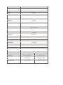
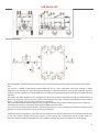
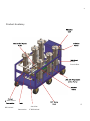
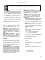
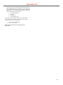
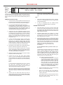
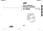
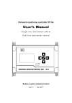
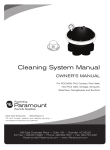
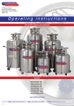
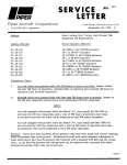
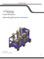
FRB-50499-240
Fuel Filtration
Operating & service manual
Contents page
Specification and consumable
1
6
Model
FRB-50499
Width
2080 mm
Depth
1100 mm
Height
1700 mm
Frame
Mild Steel
Finish
French Blue
Voltage
240 VAC ±5% Single Phase
Frequency
50 Hz ±2%
Current
32 Amps
Power
2.2 kW
Motor protection
Pump 1
Single phase motors are provided with an automatic thermal
protection switch
Self priming progressing cavity type
Noise level
<70dB @ 1m from the pump under normal working
conditions
Duty cycle
Continuous
Filtration
Water removal / Particulate removal
Filter Indicator
Visual differential pressure
Pressure
10 bar max
Temperature
-5°C - 80°C
Flow
100 L/min @ 3 bar
Medium
Diesel
Environment
IP55
Connections
2” BSP
Over pressure safety
Consumables
Electrical 3.5 Bar | Mechanical 4 Bar
Rating
Part No.
10 micron Nom
FT-19PP010-2GYEP
5 micron Nom
FT-19PP005-2GYEP
High Efficiency
1 micron Nom
FT-19HE001-2GYEP
Filtasorb 2
1 micron Nom
FT-FA-02-001
Filter Bags
FRB-50499-240
Fluid circuit diagram
The FRB-50499 is a mobile filtration system for the removal of particulate and water contamination from diesel
fuel.
The system is capable of delivering contaminated fuel up to a very respectable 100 L/min through a robust
progressive cavity pump. The fuel is then passed through 2 x 2 sets of particulate removal cells in parallel, and then
through a further 2 cells which can be fitted with our water removal media (Filtasorb 2) this gives a staged filtration
approach.
The system has been designed to run through all the filter cells as well as separately through 2 individual banks of
filters, this allows the user to carry out a filter media change or any other necessary maintenance to each bank of
filters.... meaning the unit can still run without any downtime.
There are sample points (SPI/SP2/SP3) at various stages of the filtration process, allowing the user to check the
cleanliness of the fuel in conjunction with Sigmas FS9001 Partical Counter.
The system has an electrical over pressure system feature which is in turn protected by a mechanical bypass which
will recircuit the fuel should the system pressure exceed 4 Bar.
A differential pressure gauge for each filter cell is mounted on the frame to allow the user to monitor the life span
of the filter media, a simple traffic light system is used to gauge the remaining life (Green, Amber, Red). It is
recommended the media be changed when the needle is towards the end of the amber part of the gauge.
8
2
Product Anatomy
Frame
French Blue
” BSP Valved
2”
Aux Inlet
BSP Valved
Connection
2” BSP Valved
FRB-50499-240
Connection
OPERATIONAL INSTRUCTIONS:
1) Connect the unit to a suitable 240 VAC, 32 amp supply.
2) Move the isolator to the ON position, the SUPPLY ON indicator will illuminate white.
3) Make sure all physical hose connections are made and the appropriate valves are open (see circuit diagram).
4) Press the GREEN PUMP START button, the PUMP RUNNING indicator will illuminate green.5) To stop the pump
press the RED PUMP STOP button.
FAULT CONDITIONS:
The following conditions will cause the pump to stop and the FAULT LED’s to illuminate. To start the pump after a
fault a manual reset is required, this is done by correcting the fault then pressing the RESET button.
1.
2.
High Pressure indicator will illuminate AMBER
Bund Alarm
indicator will illuminate AMBER
Any activation of either Emergency Stop buttons requires a manual reset of the system, this is done by
resetting the E-stop switch (twist until it pops out) and pushing the E-STOP RESET button.
10
FRB-50499-240
Installation & operating instructions
Bag filter housing
This housing is suitable at the operating parameters stated, for all liquids classified as Group 2. This fluid group is as
defined in the European Pressure Equipment Directive 97/23/EC.
Design Data:
Working Temperature:
Maximum Working Pressure:
Vent:
Max.: 110°C
Liquid: 10Bar g Connections:
Inlet:
the higher of the two larger connections
Outlet: the lower of the two larger connections
located in the lid of the housing
Drain: located
in the bottom
Installation:
Vent: Fit the blanking cap/plug (supplied) or the vent and gauge kit as appropriate to the lid. Seal with the aid of PTFE
tape or an appropriate sealant as required.
Inlet/Outlet: Connect the inlet and outlet pipework to the housing connections.
For threaded connections use PTFE tape or an appropriate sealant as a seal. For flanged connections use a suitable
gasket and for dairy connections use the correct sealing ring.
It is important that the pipe work to and from the filter is adequately supported.
BEFORE OPERATING WE RECOMMEND THAT THE FILTER IS FLUSHED THOROUGHLY.
**IMPORTANT SAFETY NOTES-PLEASE READ BEFORE USING THIS HOUSING**
1.
2.
3.
4.
5.
6.
Never attempt to open the housing whilst under pressure.
Never operate the housing outside of its permitted operating parameters as stated (i.e. over pressure, under
vacuum, over or under temperature).
Housings using Vee clamps should not be used in cyclic pressure or shock load environments, or where
highly viscous fluids could solidify the closure seal.
For safety, it is recommended that a pressure relief device is installed in the system to prevent overpressurisation.
Never use the housing for fluids other than those it is rated for and ensure that the housing & seal materials
are compatible with the process fluid.
Care must be taken to protect operators from hot surfaces if the housing is being run at high temperatures. 7.
Failure of the filter housing could result from misuse - please ensure that these installation, operating &
maintenance procedures are strictly adhered to.
The following factors have not been considered in the design of this housing, as they are either negligible or not
considered appropriate for this product, unless specifically stated:
1. Static pressure/head
2. Traffic, wind and earthquake loading
3. Decomposition effects of unstable fluids
4. Creep, fatigue and corrosion allowances
5. External fire
Operation:
IMPORTANT: ALWAYS ENSURE THAT THE SYSTEM IS NOT UNDER PRESSURE BEFORE OPENING THE
HOUSING
FRB-50499-240
Opening the filter - For housings with a Bolted closure
If the filter housing has been in service, refer to the instructions given in the section “Removing the Filter from
12
FRB-50499-240
Service”. Unscrew the clamp bolts with a suitable spanner. Swing the clamps clear of the cover. Remove the lid and
‘O’-ring. Store them in a safe place where they cannot get dirty or damaged. Remove the basket compression plate.
Fitting the Perforated Basket
The housing is supplied with a perforated bag support basket. There is an inner gasket fitted under the basket. Check
the ‘O’-ring groove and inner gasket for any damage, and place inner gasket in the groove. Place the basket into
position ensuring that the inner gasket does not become dislodged.
Fitting the Filter Bags
Push the bag into the basket that is situated in the housing and check that the filter bag ring is fitted flush to the
basket flare. Position the bag compression plate onto the top of the bag ring, with the large plate fitting against the
bag in the basket lip. This will compress the bag and basket against the inner gasket.
Closing the Filter Housing - For housings with a Bolted closure
Check the housing top ring and groove, the ‘O’-ring and lid for any dirt or damage. Clean away any foreign objects and
replace defective parts as necessary.
Place the ‘O’-ring into the groove at the top of the housing. Position the lid evenly over the housing ensuring the seal
is not disturbed.
Swing the screw clamps up into position ensuring that the clamp locates correctly in the grooves on both the lid and
housing top ring. Screw the clamps down evenly. Before tightening ensure the lid is set squarely on the housing top
ring. Finally nip down the screw clamps with a spanner in a diagonal basis across the filter housing. DO NOT over
tighten.
Putting the Filter into Service
Ensure the inlet and outlet valves are shut. Ensure that the drain valves (if fitted) are closed or the drain plugs are
fitted.
Open the vent valve or plug.
Gradually~ open the inlet valve on the upstream side of the filter housing whilst ensuring that the down stream valve
remains closed.
As the housing fills, air will be expelled from the vent. When all the air has been expelled, fluid will begin to flow from
the vent. For safety reasons, it is important to ensure that vent and drain connections are secure and that released
fluid is disposed of to an appropriate drain or container. Appropriate measures should be taken if the liquid is
hazardous.
Close the vent valve or plug, then slowly open the outlet valve-the filter is now in service and no attempt should be
made to open the cover.
Regular venting of the housing, by opening the vent to permit any trapped air to vent to atmosphere, will maintain
the operating efficiency of the filter. For safety reasons, it is important to ensure that venting is ONLY performed via a
valve, that the valve is opened with extreme care and that released fluid is disposed of to an appropriate drain or
container. Appropriate measures should be taken if the liquid is hazardous.
The filter can be operated until the increase in the pressure differential across the filter bag reaches approximately
1.5 bar g (25psi), at this point the filter bag should be replaced.
Removing the Filter from Service
Close the outlet valve
Close the inlet valve
Caution- the filter housing will still be under pressure at this point.
Before opening the filter housing, the pressure must be relieved. This can be done either by carefully opening the
vent valve or plug or the drain valve or plug, whichever is most appropriate.
13
FRB-50499-240
Before opening the closure, open both the dirty drain and clean drain valves or plugs to allow all of the fluid to drain
out of the housing. The vent must be open to allow the housing to drain properly. If the fluid is hazardous,
appropriate measures should be taken before opening the closure.
For safety reasons it is important to ensure that vent and drain connections (such as any valves or hoses) are secure
and that released fluid is disposed of to an appropriate drain or container.
Replacing the Filter bags
Open the filter housing according to the instructions given in the section “Opening the filter housing” The new filter
bags should be installed according to the instructions described under “Fitting the Filter Bags”.
Spent Filter Bag Disposal
The spent filter bags should be disposed of in a responsible manner. The filter itself can be disposed of by incineration
or as landfill by an authorized contractor; however, it is important for the user to check how the contaminant
contained in the filter should be disposed of.
Maintenance
The filter housing will require very little maintenance.
The outer surface should be kept clean and free from dirt. This will prevent contamination of the filter during bag
change.
The Vee clamp should be maintained as follows:
A small amount of a suitable lubricant should be used on the sliding surfaces of the clamp. The ‘T’ bar thread must
periodically greased. We recommend the use of a molybdenum based grease which will adhere to the thread.
Binding of the thread could occur if they are not lubricated regularly. Inspect the ‘O’-rings each time the filter
housing is opened and replace as required.
The housing must be checked for any visible signs of corrosion or wear damage internally and externally on a routine
basis.
Internal examination should be carried out via the housing closure.
6. Always use genuine ROTO spares for sustained pump
performance and longer life of critical parts.
DON’TS
1. Never run the pump in a dry condition even for a few
revolutions otherwise the rotor will damage the
stator immediately.
2. Never run the pump against a closed inlet or outlet
valve.
3. Never use foot valve for slurry applications.
4. Never vary flow rate by throttling suction and
delivery line.
5. Never exceed recommended pump speed.
6. Never reverse the recommended direction of
rotation of pump without consulting ROTO.
7. Never use local made or spurious spares that look
alike but do not meet material standards or
dimensional accuracy affecting life of critical
components and performance of pump.
8. Care is required when adjusting the gland while
pump is running.
COMMISSIONING - All nuts and bolts, securing flanges and
base mounting fixtures, must be checked for tightness before
operation. To eliminate vibration, the pump must be correctly
aligned with the drive unit and the guards must be securely
fixed in position. All the pipelines must be independently
supported and use of expansion joints is desirable to eliminate
the transmission of vibrations and stresses to the pipelines.
When commissioning the plant, all the joints in the system
must be checked thoroughly for leakage. If on starting, the
pump does not appear to operate correctly, the pump must be
shut down immediately and the cause of the malfunctioning
must be established before operations are recommenced. It is
recommended that depending upon plant system operation
either a combined vacuum gauge and pressure gauge, or a
vacuum gauge only, be fitted to the pump inlet port and a
pressure gauge fitted to the outlet port to continuously monitor
the pump operating conditions. It is further recommended that
a pressure relief valve of adequate capacity should be installed
on the discharge side of the pump.
START UP/RUNNING
DRY RUNNING - Pumps must be filled with liquid before
starting (A threaded plug has been provided on the top of the
pump housing for this purpose). The initial filling is not for
priming purpose, but to provide the necessary lubrication of the
stator until the pump primes itself. When the pump is stopped,
sufficient liquid is normally trapped between the pumping
elements to provide the necessary lubrication for restarting. If,
however, the pump has been left standing for a long time or
has been dismantled, it must be refilled with liquid and given a
few turns before starting, to get sufficient lubrication between
the rotor and stator.
If the pumping liquid is hazardous, then extreme care must be
taken while initial filling of the pump using all safety and
precautionary measures.
NEVER RUN THE PUMP IN A DRY CONDITION EVEN FOR
A FEW REVOLUTIONS OTHERWISE THE STATOR
WILL BE DAMAGED IMMEDIATELY
14
FRB-50499-240
INSTALLATION, OPERATION & MAINTENANCE INSTRUCTIONS
INSTALLATION, OPERATION & MAINTENANCE INSTRUCTIONS
GLAND PACKING
The pump is normally fitted with gland packing, which required
final adjustment during initial running period. Under normal
working conditions the gland rings are to be tightened in a
manner to permit a slight drip from the gland. This enhances
life of the shaft as well as of gland packing. It is important to
note that the gland packing never be over tightened to arrest
the leakage completely. This can lead to excessive heat
generation that can cause permanent damage to shaft and
packing. Adjustment by tightening should only be made when
the pump is running. Indication of slight drip from the gland
packing will only be evident if the pump is running delivery on
gland or with suction on gland with a flooded suction. If the
pump runs with a vacuum on the gland, a flushing connection
(or greaser) with lantern ring is recommended.
Where lantern rings are fitted in stuffing box; the flushing
liquid inlet or outlet should be connected for proper circulation
of the liquid.
MECHANICAL SEAL - When the pump is supplied with
mechanical seal, it may be necessary to ensure proper
flushing & quenching arrangement as per the seal
manufacturer’s recommendations, enclosed with this
manual.
GLAND GUARDS - In the interest of safety of personnel and
in compliance with statutory requirements of various
countries, the pumps are fitted with gland-guards that can be
easily removed for adjustment of gland sealing. It is
responsibility of the user to make sure that the guards are
placed back in position after necessary adjustments have
been made.
LUBRICATION - The pump should be inspected periodically
for lubrication of bearings to see if grease replenishment is
required, and if so, grease should be added in accordance
with the instructions given in assembly procedure.
MAINTENANCE OF WEARING COMPONENTS ROTORS
AND STATOR - The wear rate of these components depends
on many factors, such as product abrasiveness, speed,
pressure etc. One or possibly both items will need to be
replaced, when the pump performance has reduced to an
unacceptable level.
DRIVE SHAFT – STUFFING BOX - The wear rate under gland
area of the drive shaft depends on various factors like product
abrasiveness, extent of tightening of the packing and speed of
the pump. Periodic inspection and maintenance of the gland
will maximize the life of the shaft. Replacement of the gland
packing or both the gland packing and the drive shaft will be
necessary when the shaft sealing becomes difficult to achieve.
UNIVERSAL JOINT - Universal joints should be examined
when the pump is dismantled for any reason or for routine
maintenance during periods of regular scheduled equipment
down time. The joints should be cleaned and renewed with
fresh grease before assembly.
Use only recommended grease as per specifications in this
manual.
PUMPSET - When a pump unit is dismantled and
reassembled, it has to be ensured that the following steps, as
applicable, are covered
1. Correct alignment of pump and driver.
2. Use of appropriate couplings and bushes.
3. Use of appropriate belts and pulleys.
PUMP OPERATING TEMPERATURE - The surface
temperature range depends upon factors like ambient
temperature and temperature of the fluid being pumped. If the
external pump surface temperature goes above 500C,
personnel must be made aware of these and suitable
warnings or guarding must be employed.
EXPLOSIVE PRODUCTS/ HAZARDOUS ATMOSPHERE In certain instances, the product being pumped may be of a
hazardous nature. In these installations, considerations must
be given to provide suitable protection and appropriate
warnings to safeguard personnel and plant.
INSPECTION
ADJUSTMENT OF GLAND PACKING - The gland packing
should be inspected every day after starting the pump.
Remove the gland guards to check the leakage. If the sealing
is not proper it must be adjusted by tightening or loosening of
gland nuts to attain the preferred level of sealing. Excessive
tightening should be avoided, as it would result in excessive
heat generation leading to permanent damage of both the
packing and the drive shaft. Experienced personnel should
carry gland adjustment carefully so that safety of the
personnel is not endangered.
SPECIAL INSTRUCTIONS
PERIODIC INSPECTION - To avoid unexpected failure of the
pump, it is important that the pump is periodically dismantled
and routine inspection of the pump is carried out as follows:
Inspection of the pumping elements for wear and tear, after
every six months or if the discharge falls below acceptable
levels.
Periodic bearings and universal joints inspection is necessary
to maintain optimum performance. The most appropriate time
to inspect is during periods of regular scheduled downtime
for routine maintenance or for any other reason
ROTATION
The RNA/RNB Series pumps are capable of taking rotation in
both the directions but if a change of direction is required,
consult ROTO or its authorized agents before doing so.
LUBRCATION
Bearings: Pumps should be periodically inspected to see if
grease replenishment is required. If so, bearings should be
cleaned and repacked with grease until the bearing chambers
are one third full with grease.
Use one of the following recommended or equivalent grease:
1. SHELL Alvaina R3
2. BP Energrease LS#
3. Castro Spheerol AP#
4. Mobilux 3
UNIVERSAL JOINTS
15
FRB-50499-240
The pin type universal coupling should be lubricated when the
pump is dismantled due to some reason. To do so pack entire
space between the coupling rod head and rotor or drive shaft
bore with one of the following recommended or equivalent
grease,after cleaning the components.
1.
2.
3.
4.
Shell Alvania grease 2
Mobilux 2
MP Grease 2
Castrol Spheerol AP2
Whenever Boot seal of EPDM materials are recommended or
used, please ensure that only the following Silicone Grease
compound is used for such applications.
1.
2.
MOLYCOTE 7 COMPOUND
OKS 1110 GREASE
NOTE: The above Greases also comply with food
applications.
16
FRB-50499-240
Before
dismantling
DISMANTLING & ASSEMBLY INSTRUCTIONS FOR
isolate
all
electrical
RMCA / RMGA – 641 PUMPS
circuits. Close
all
isolation
9. Unscrew the Hex Head Nut (42) and collect Spring
valves on the suction and discharge to the pumps are prevention
Washer (43) & Punched Washer (44). Take out the
of liquid escaping from the pipe work system. The persons carrying
Pump Lantern (1200) and also remove the Tap End Stud
out the work should be adequately trained in general workshop
(41).
practice, relevant to the class of work involved & taking care of
safety.
Note: DISMANTLING INSTRUCTIONS:
1.
2.
3.
Unscrew the Hex. Nuts (15) fitted to the Tie Rods (7710)
and remove the Spring Washers (16), Plain Washer (36),
End Cover (5310), Tie Rods (7710) and Foot (0760).
To remove the Bonded Stator (2220) from Pump
Housing (5020) , pour some water or soap solution into
the Bonded Stator (2220) through the opening in the
Pump Housing (5020) to ease the stiffness. Move out
the Bonded Stator from the Rotor (2500) by rolling in the
clockwise Direction looking from the drive end.
Unscrew the Four Hex. Head Bolts and Nuts (21,22),
holding the Pump Housing (5020) to Stuffing Box (5810)
and withdraw the Spring Washers (23), Plain Washers
(37), Pump Housing (5020), taking care of any undue
rubbing on the Rotor (2500) & Coupling Rod (2610).
Rotor may be protected by covering with some soft
material like cloth.
4.
In order to dismantle the Rotor (2500), Universal Joints
(20) have to be dismantled. Remove the External
Circlips (06), Pin Retainer Sleeves (2820) Boot Seal
Retainers (2810) and drag out the Boot Seal (1510) and
collect the grease. Remove the Spring Pins (01) and
knock out the UJPins (2920) from UJ Head (4010).
5.
Dismantle the Rotor (2500) from Coupling Rod (2610).
Remove UJ Bushes (2730) and UJ Block (4110).
Now knock out the C/Rod Pins (2910) from UJ Heads
(4010), holding Rotor (2500) and Coupling Rod (2610).
Remove UJ Heads (4010) and O-Rings (02,03,04) from
UJ Head and Stub Shaft / Coupling Rod.
6.
Repeat the same for other Universal Joint (20), Coupling
Rod (2610) and Stub Shaft (4400).
7.
Unscrew the four Hex. Nut, Stud, Spring Washer
(09,101,11), Slip out the Stuffing Box (5810) and Gland
(5410) assembly and unscrew two Hex Nuts and Studs
(07,08) to remove the Gland (5410) and Gland Packing
(7500).
1.
Clean all the parts and check them for wear / damage.
The worn out / damaged parts should be replaced with
original ROTO Spares.
2.
In order to dismantled parts use suitable antirust
compound on the Metallic surface of component.
ASSEMBLY INSTRUCTIONS:
1.
Align Stub Shaft in such away so that the motor shaft
hole is in line with Stub Shaft locating hole. Insert Dowel
Pin (2930) through Stub Shaft and motor shaft. Locate
Pin Retainer over Dowel Pin over Dowel Pin and Secure
tightly with Set Screw (45).
2.
Assemble Geared Motor (40), locating it on Pump
Lantern (1200) and securing with Hex Bolts / Studs, Nuts
and Washers (41,42,43,44), while keeping the Geared
Motor Supported from overhead.
3.
Fill the Gland Packing (7500) in the Stuffing Box (5810)
and locate the gland (5410) as shown. Secure the Gland
(5410) and Stuffing Box (5810) by Studs (07) & Hex Nuts
(08). Insert this Sub assembly over the Stub Shaft
(4400). Secure the Stuffing Box (5810) to Pump Lantern
(1200) by four Hex Nuts, Studs and Spring
Washers (09,10 & 11 resp.) as shown in the
C.S.Drawing).
In case of Mechanical Seal, proceed as under: (Ref.
RN-10-144)
Locate Stationary Seat with Seal Ring in the Seal Plate
(5451) in position applying even pressure. In case of
Teflon O-Ring with Stationary Seat, fitment shall be
made by applying pressure on to the Stationary Seat
Under a small press or Drill Machine Spindle, using a
soft pack on the face of the seat while driving the
stationary seat in the Seal Plate (5451).
•
Fit the Seal Plat with Mechanical Seal
Housing (5861) after putting the ‘O’ Ring (33)
and locate the assembly in place on the Pump
Lantern (1200). Measure distance ‘L1’ from
Stub Shaft (4400) end to face of stationary
seat. Now take out the Mechanical Seal
Housing assembly with seal plate. If operating
length of Mechanical Seal is ‘L2’ mark a
distance ‘L’ on the Stub Shaft (4400) equal to
‘L1-L2’ from UJ end of the Stub Shaft.
•
Take out Seal Plate (5451) from the Seal Housing
(5861) by unscrewing the nuts (32).
•
Slide over the Seal Plate (5451) with Stationary
Seat on to the Stub Shaft (4400) towards Pump
Lantern (1200) side.
•
Insert Rotary Part of the mechanical Sea onto the
Stub Shaft (4400), taking extreme care not to
damage any part of the seal.
Note: In case of Mechanical Seal (Ref. RN-10-144), unscrew
Hex Nuts (32), connecting Seal Plate (5451) &
Mechanical Seal Housing (5861). Remove Mechanical
Seal Housing (5861) & collect ‘O’ Ring (33).
Now remove setscrews from drive collar of Mechanical
Seal (30) and take out Mechanical Seal. Remove Seal
Plate (5451) along with Stationary Seat of Mechanical
Seal.
8.
Unscrew four Hex Socket Set Screw (45) from Pin
retainer (2850) & remove the Pin Retainer (2850) sliding
towards the Head side. Knock out the Dowel pin (2930)
and remove the Stub Shaft (4400).
17
FRB-50499-240
DISMANTLING & ASSEMBLY INSTRUCTIONS FOR
RMCA / RMGA – 641 PUMPS
•
•
4.
Now tight the Drive Collar of Mechanical Seal in
place, on the mark at distance ‘L’ over the Stub
Shaft, with Setscrews. In case Stub Shaft is Hard
Chrome Plated, tight the Setscrews on the Stub
Shaft after removing plating at places to be
screwed, by a small hand grinder.
Now fit Mechanical Seal Housing (5861) between
Pump Housing (5020) and Pump
Lantern (1200). Pull Seal Plate (5451) to the Seal
Housing (5861) and tight in place with Studs (31),
Spring Washers (34) & Hex Nuts (32). Secure the
Mechanical Seal Housing (5861) to Pump Lantern
(1200) by four Hex Nuts, Studs and Spring
Washers (09,10,11 resp.).
To proceed further, assembly of Universal Joint (20) has to be
done as under:
Clean all the internal surface of U.J. Head (4010) and place
the ‘O’ Rings (02,04) in their respective grooves. Also place
the ‘O’ Rings (03) in the Stub Shaft groove. Place one
External Circlip (06), Pin Retainer Sleeve (2820) and Boot
Seal Retainer (2810) on Stub Shaft (4400), Stuffing Box Side.
Fit the U.J. Head (4010) on Stub Shaft (4400) and insert the
C/Rod Pin (2910) after aligning the hole in the U.J. Head
(4010) and Stub Shaft (4400).
5.
Apply some grease on the OD pf U.J Bush (2730) and insert
it in the holes of U.J. Head (4010) taking care that scratches
does not comes on the Bush ID or OD while fitting.
6.
Offer the U.J. Block (2730) in another U.J. Head (4010)
mounted at Stub Shaft (4400), after aligning the U.J. Block
(4110) and Bush (2730) holes, insert the U.J. Pin (2920) and
lock it by the Spring Pin (01).
7.
Fit the U.J Bush (2730) in another U.J Head (4010) after
placing ‘O’ Ring (04 & 02) and offer it to other side of U.J Block
(4110) (already assembled in step 7), insert the U.J .Pin
(2920) after aligning the U.J Bush (2730) and U.J Block
(4110) holes and lock it by Spring Pin (01). Now drag the Boot
Seal (1510) at its position taking care that it rests on the
grooves in U.J Head (4010).
8.
Insert External Circlip (06). Pin Retainer Sleeve (2820) and
Boot Seal Retainer (2810) respectively on the Coupling Rod
(2610) and place ‘O’ ring (03) in the Coupling Rod groove.
9.
Fill the grease inside the U.J (20) fitted on the Stub Shaft
(4400) and insert the Coupling Rod (2610) in the U.J Head
care of alignment of the C/Rod Pin holes at Coupling Rod and
U.J Head, now insert Coupling Rod Pin (2910).
Washer
(11)
,
locating Stuffing Box
(5810) in position
between
Pump
Lantern and Pump
Housing.
14. To assemble the Stator (2220) pour some water or soap
solution into the Stator to ease the stiffness. Push the Stator
over the Rotor forcing it towards the Pump Housing by rolling
it over the Rotor (2500) in the Anticlockwise Direction looking
from the drive end, till it butts with the Stator Support Ring
(6220).
15. Place the two Foot (0760) in the position as shown and offer
the End Cover (5310) to Stator (2220). Thread up Nut and
Washers (15,16,36) each on topsides. Insert these Tie Rods
in the holes in End Cover (5310) and Pump Housing (5020).
Also insert two Tie Rods (7710) on top side tighten the four
Tie Rods (7710) by with Nuts, Spring Washers and Plain
Washers (15,16,36).
16. After total assembly of the pump, put it on a flat surface to
check that Foot (0760) are lying co-planner and also place the
Gland Guards (7620). Ensure that all the fasteners except
Gland Nuts (08) are tightened properly.
10. Place the Boot Seal Retainer (2810), Pin Retainer Sleeve
(2820) and secure it with External Circlip (06) at both side of
the Universal joint.
11. To assemble U.J (20) on the Rotor (2500) repeat Steps 5 to
8.
12. Repeat the steps 9 to 11 to assemble Coupling Rod (2610)
and Rotor (2500).
13. Placing the Stuffing Box Gasket (8120) at its location, drag
the Pump Housing (5020) without touching the Rotor (2500).
And connect it by tightening the Hex. Nut (10) after placing
the Hex Head Bolts (09), Punched Washer (37) & Spring
18
19