1
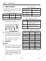
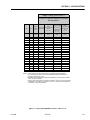
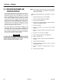
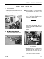
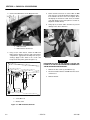
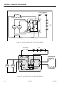
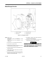
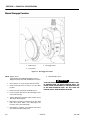
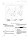
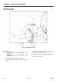
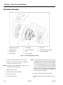
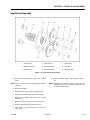
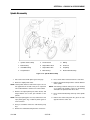
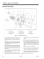
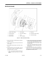
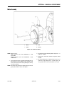
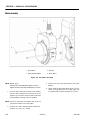
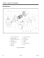
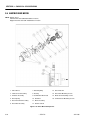
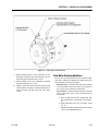
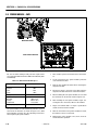
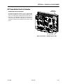
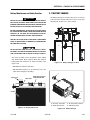
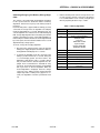
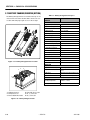
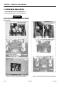
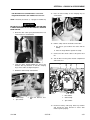
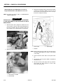
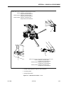
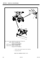
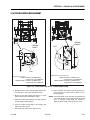
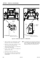
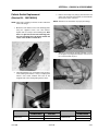
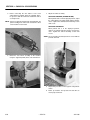
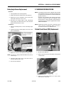
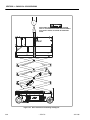
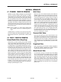
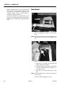
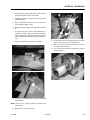
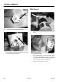
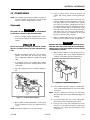
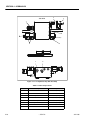
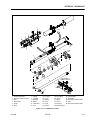
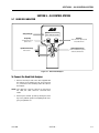
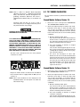
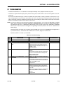
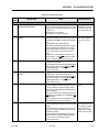
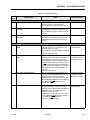
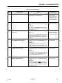
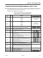
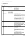
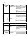
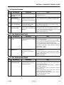
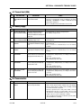
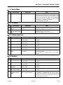
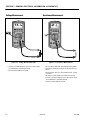
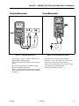
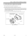
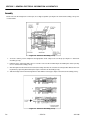
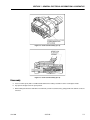
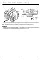
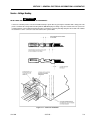
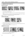
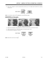
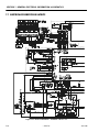
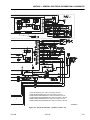
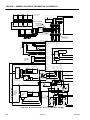
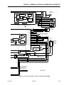
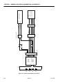
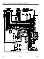
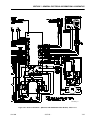
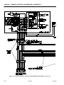
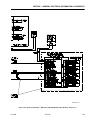
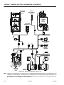
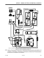
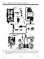
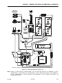
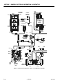
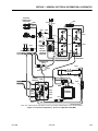
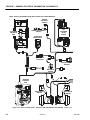
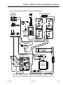
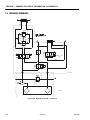
SECTION 3 - CHASSIS & SCISSOR ARMS
Motor and Brake Assembly
13. Brake Cover
17. 5. Disc Brake
21. Retention Bolt
14. Disengage Bolts
18. Motor
22. Washer
15. Socket Head Screws
19. Thru Bolts
16. Brake Housing
20. Spacers
Figure 3-18. Motor & Brake Disassembly
NOTE: Applies only to:
USA machines built prior to S/N 0200118041,
Belgium machines built prior to S/N 1200001487.
NOTE: Keep the brake disc clear of any oil or grease.
1. Remove back sealing cover from motor if it is not
already removed.
2. Remove retention bolt and washer from the motor
shaft end. Do not let the armature shaft fall out of
the open end of the motor.
3. Open up Brake Kit. It should have a brake housing,
brake disc, and three spacers.
4. Install Brake disc onto splined end of motor shaft.
3121166
– JLG Lift –
5. Reinstall the retention bolt and washer into the shaft
end to keep the armature in the motor.
6. Install the brake housing onto motor end cap; use
the included spacers to space the brake housing
from the motor end. There may be motor wires in the
way. Push them aside to mount the brake.
7. Fasten with 3 Bolts to a torque of 4 - 5 ft.-lbs.
8. Remove the disengage bolts from the brake housing
and install them into the tapped holes in the motor
end cap for storage.
3-21