1
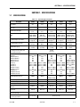
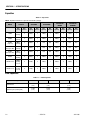
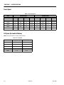
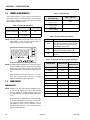
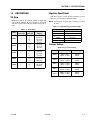
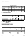
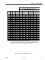
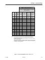
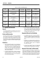
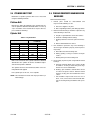
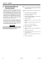
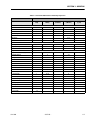
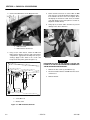
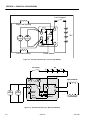
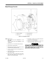
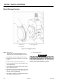
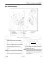
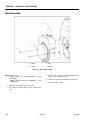
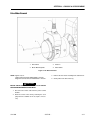
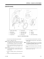
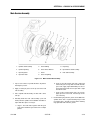
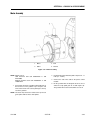
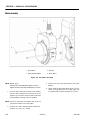
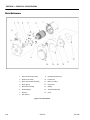
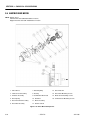
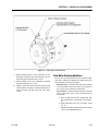
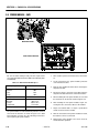
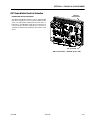
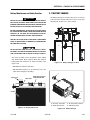
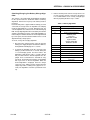
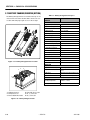
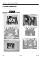
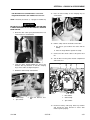
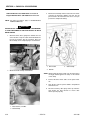
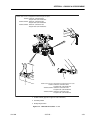
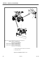
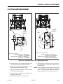
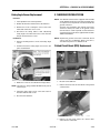
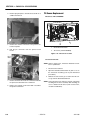
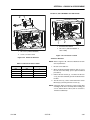
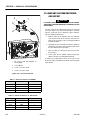
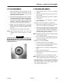
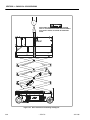
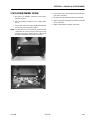
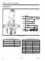
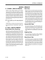
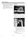
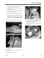
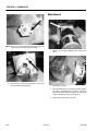
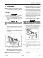
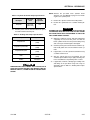
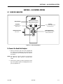
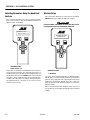
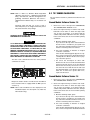
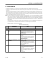
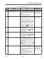
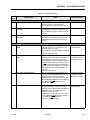
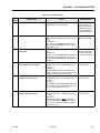
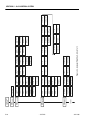
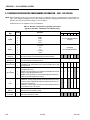
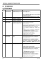
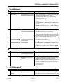
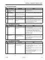
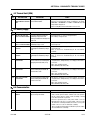
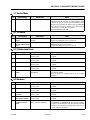
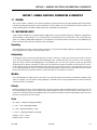
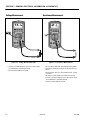
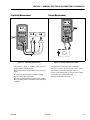
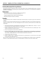
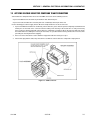
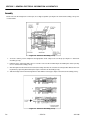
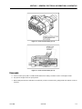
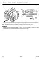
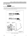
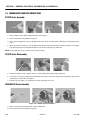
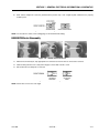
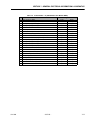
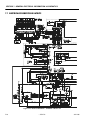
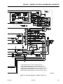
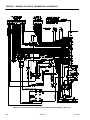
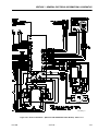
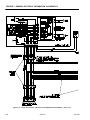
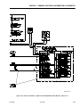
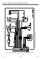
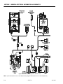
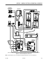
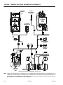
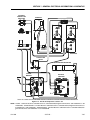
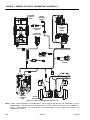
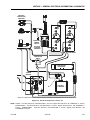
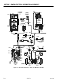
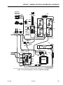
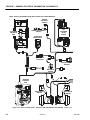
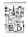
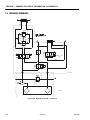
SECTION 3 - CHASSIS & SCISSOR ARMS
3.8 POWER MODULE - SEVCON
F1
P
M2
M1
B+
B-
F2
MACHINE FRONT
SEVCON POWER MODULE
Figure 3-32. Sevcon Power Module Location
The Sevcon Power Module, P/N-1600346 was replaced by
the ZAPI Power Module (See Figure 3-33.) on macines
built starting in mid year 2010.
Use the following instructions when replacing the Power
Module.
1. Make sure power to the machine is turned off and
the batteries are disconnected.
Table 3-1. Sevcon Power Module Specs
Operating Voltage (Pin 1 and B+)
Maximum Current Limits:
Armature
Field
Pump
Standby Current
NOTE: Note the wire terminal locations when removing the
old Power Module.
2. Disconnect all wires from the old Power Module and
remove from the machine.
14.5 to 40 VDC
350 A
40 A
150 A
3. Before bolting the Power Module on, using a V-notch
trowel, apply a layer of heat transfer grease to the
back of the new Power Module.
150 mA
Temperature Range:
Operating
Storage
Thermal Limit
-30°C to 40°C
-40°C to 70°C
75°C to 90°C
Switching Frequency
16 kHz
4. Be sure that the terminals are oriented as shown.
5. After installing the new Power Module, begin connecting the wires back to the controller.
The Power Module is located at the front of the machine
as shown in Figure 3-32., Sevcon Power Module Location.
3-38
– JLG Lift –
6. Torque the M6 terminal bolts to 5 ft-lb. (7 Nm).
Torque the M8 terminal bolts to 7 ft-lb. (10Nm).
7. After all connections to the Power Module are made,
the battery can be reconnected.
3121166