1
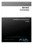
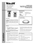
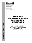
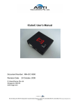
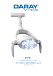
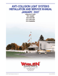
®
Installation Guide:
Model 70899( )
Strobe Power Supply Assembly
TSO-C96a Approved.
ENGINEERING COMPANY INC.
Route 145, Winthrop Road,
Chester, Connecticut 06412
Phone: (860) 526-9504
Fax: (860) 526-2009
Internet: www.whelen.com
Sales/Service e-mail: [email protected]
Specifications
The conditions and tests required for TSO approval of this
article are minimum performance standards. It is the
responsibility of those installing this article either on or
within a specific type or class of aircraft to determine that
the aircraft installation conditions are within the TSO
standards. TSO articles must have separate approval for
installation in aircraft. The article may be installed only if
performed under 14 CFR part 43 or the applicable
airworthiness requirements.
Model Number - 7089900
Part Number - 01-0770899-00
Current Draw - 2.4 Amps @ 28 Volts D.C.
Weight 1.8 lbs.
Length 5.5”
Height 3.0”
Width 5.0”
OPERATION: This power supply will operate up to 2 strobe
light head assemblies. Total power to each output is 36
joules. Output 1 alternates with output 2. The typical
configuration is to connect output 1 to one wingtip strobe light
assembly and output 2 to the other wingtip strobe light
assembly.
CONTINUED AIRWORTHINESS: The power supply output
should be checked on a regular basis for flash rate. The flash
rate may be checked by indirect observation of the strobe
lighthead. Do not look directly at the strobe light. If the strobe
does not appear to be functioning correctly, try to determine if
the problem is with the power supply or the strobe lighthead.
This can be accomplished by replacing the strobe tube or
lighthead assembly with a good operating unit or with the use
of a Whelen Strobe Check unit.
Periodically check the power supply connections and wiring.
Also, check and tighten or clean the Ground wire connection
at the power supply case.
Aviation
EQUIPMENT LIMITATIONS: An approved Anti-Collision
System consists of Power Supply 70899( ) connected to two
Whelen Strobe Light Assemblies, model A650 Series, A600
Series or A625 Series.
Fig. 1
MADE IN THE U.S.A.
TYPICAL STROBE HOOK-UP:
PIN 1 - RED - ANODE
PIN 2 - BLACK - CATHODE
PIN 3 - WHITE - TRIGGER
INSTALLATION PROCEDURES:
Location
1.
Consider areas or locations designated by the aircraft
manufacturer. Do not mount the strobe power supply
any closer than 3 feet from the ADF loop.
2.
For alternate locations, consider areas such as the
cabin baggage compartment, the floor under the seat,
non-structural bulkheads, firewalls etc.
3.
If necessary, fabricate support brackets or shelves, and
attach them to the aircraft structure to provide a
mounting surface that will withstand the inertia forces
stipulated in chapters 1 & 3 of AC 43.13-2A
4.
An “IA” or other representative of the FAA must approve
documentation of structural integrity of the fabricated
installation.
5.
Specifically call out the location of the strobe light power
supply on FAA form 337.
Wiring
WARNING: STROBE LIGHT POWER SUPPLIES ARE
POLARITY SENSITIVE. REVERSING THE INPUT
POLARITY WILL CAUSE SEVERE DAMAGE TO THE
POWER SUPPLY.
Steps below: “Ref. AC 43.13-1B, Chapter 11, Sections 1,2,3,
& 7”.
1.
Choosing wire size of A+ input lead, refer to Paragraph
444 “Electric Wire Chart” Figure 11.7 and 11.7A, with
reference to Strobe Light Model Current requirement
chart on page 6 and 11, and “Wire and Circuit
Protection Chart” Figure 11.1.
2.
Shielded wire is not generally necessary, but has
proven effective in reducing the possibility of radio
interference.
3.
The power supply shall acquire its power from a low
impedance source such as the alternator or generator
end of the electrical buss as close to the battery as
possible.
4.
For penetrating pressure hull, refer to the aircraft
service manual.
5.
Check all avionics systems for interference.
PIN
(1) +
(2) (3) SYNC.
Connector for
Input Power Cable
1 TYP.
2 TYP.
3 TYP.
Outlet
1
Outlet
2
STROBE OUTLETS
©2005 Whelen Engineering Company Inc.
Form No.14021 (102405)
Page 1
Interconnecting Cable
IMPORTANT NOTE:
1.
Your new strobe power supply has an additional circuit
built-in to prevent self-ionization (steady glowing) of the
strobe tubes. In some cases, when replacing older power
supplies, the bare shield wire in the existing harness is
pinned together at each end with the black wire. The
following modification must be made to ensure proper
operation.
2.
3.
The Whelen interconnecting cable shall be secured in place with
approved aviation techniques.
The cable shall not parallel ADF, Gyro or Flux Gate compass leads
closer than 12 inches.
CABLE COLORING CODING (see Figure 3):
PIN 1 - RED (Anode)
PIN 2 - BLACK (Cathode, flash tube ground)
PIN 3 - WHITE (Trigger)
SHIELD - Ground at power supply end only
CAUTION: When pins 1 & 2 or pins 2 & 3 are reversed, the
system will appear to operate normally, however this
condition will cause premature flash tube failure.
1.
2.
3.
Fig. 2
At the strobe tube end of the cable, cut the shield wire and tape it off
(DO NOT CUT THE BLACK WIRE).
At the power supply end of the cable, cut the shield wire and connect
it to a good ground (DO NOT CUT THE BLACK WIRE).
This must be done for each strobe light connection (see Fig. 2).
PIN 1 = RED (ANODE)
PIN 2 = BLACK (CATHODE)
PIN 3 = WHITE (TRIGGER)
SHIELD = RFI DRAIN TO GROUND
3 POS. PIN HSG
POWER
SUPPLY
END
3 POS. SOCKET HSG
1
2
3
3 CONDUCTOR SHIELDED CABLE
SHIELD WIRE
1
2
3
X
STROBE
TUBE
END
CUT AND TAPE SHIELD WIRE
AT STROBE TUBE END
GROUND SHIELD WIRE
AT POWER SUPPLY END
INTERMIXING STROBE LIGHT SYSTEM EQUIPMENT
OBSERVE COLOR AND PIN NUMBERS. CABLES CONNECTING REMOTE
POWER SUPPLY TYPE STROBE LIGHTS MUST BE CONNECTED CORRECTLY!
Whelen Engineering and Aero-flash wiring
between light assemblies and remote
power supplies are identical as pictured
below.
Grimes and SDI (Hoskins) wiring between
light assemblies and remote power supplies are identical as pictured below.
SHIELD
R
HI
TE
ED
W
BL
AC
K
BL
WH
ITE
AC
K
SHIELD
CLIP
R
ED
Both Grimes and SDI sometimes use MS
(Cannon Type) Connectors:
A = RED (Anode), B = WHITE (Trigger),
C = BLACK (Ground)
Page 2