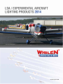
1
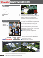
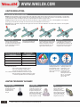
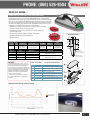
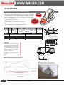
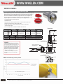
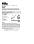
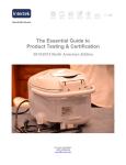
Photo courtesy of Team Aerodynamix
ISO 9001 Registered QMS
INDEX
Index / Company Profile
Whelen Corporate Capabilities
Lighting Regulations
Anti-Collision Lightheads
1
2-4
5
6-12
Position / Navigation Lights
13
Power Supplies
14
Wingtip / Tail Lighting
15
Parmetheus Series
16-17
Recognition Lights
18
It all started 1952 in a garage with the first Rotating Beacon.
Misc.
19
Strobe to LED Replacement
20
Where it all began...
How to Choose a Lighting Package
21
A privately owned company, Whelen has experienced positive growth for over
60 years. The pride and commitment of its work force, whose employment
longevity averages over 22 years, is rewarded through a profit sharing plan
established by the Whelen family since the company was founded.
System Recommendations
22
The development of the first aviation light helped launch Whelen into the
automotive safety lighting industry as well.
MEET THE TEAM
TOP RIGHT:
OFFICE - GREG, JEFF, BRYAN,
SHARON, JESSICA, & TRISH
BOTTOM LEFT:
CORPORATE PILOT - JIM
BOTTOM RIGHT:
CORPORATE PILOT - DENNIS
Whelen currently provides safety lighting for Police, Fire, EMS, and DOT
professionals as well as many other industries. The production volumes seen
in the automotive sector have allowed Whelen to invest in the latest automated
assembly equipment in order to compete world-wide. Last year Whelen
purchased over 44 million LEDs for use in their extensive family of products.
In the 1970s, Whelen introduced the Outdoor Warning Siren ... totally
electronic and capable of not just warning tones but also high-powered voice
messages. The Mass Notification Division has saved lives around the world.
At Whelen Engineering, our goal is to bring innovative, life saving products to
market more quickly while maintaining strict quality control throughout the
process. We have accomplished this through a vertical manufacturing initiative
to eliminate or reduce out-sourcing; the use of robotics and state-of-the-art
production equipment; and, perhaps most importantly, a motivated workforce
of over 1100 employees. This allows us to meet and adapt to our customer’s
changing needs in the shortest amount of time.
■ Two manufacturing facilities totaling over 586,000 square feet.
■ Largest staff of Design Engineers in the industry.
■ Research and development.
■ Partnering with OEMs on new vehicle design and product integration.
■ Plastics injection molding machines from 30 to 2000 tons capacity.
■ In-house plastics, hard-coating, metallizing, & sheet metal fabrication.
■ On-site test lab for environmental dust, moisture, vibration, etc, acoustic
anechoic sound chamber, industry certifications (SAE, AMECA, FAA to
name a few).
■ Sales and Technical Personnel are trained at the factory training center and
return for updates on a regular schedule.
■ Worldwide network of Sales, Service and Training.
MANUFACTURING FACILITIES
Corporate Headquarters, Chester, Connecticut
Charlestown, New Hampshire Division
Makers of Aviation, Automotive and Industrial Safety Lighting since 1952
Whelen Aviation Warning Products are all designed, assembled, tested and manufactured in the United States of America.
CONTACT US: WWW.WHELEN.COM or [email protected]
1
All non-FAA approved parts in this catalog are signified by a (—) in the approval column. Parts without FAA approval may still be purchased, however,
installation of these parts on U.S. Type Certificated products will require FAA approvals.
WHELEN CORPORATE CAPABILITIES DESIGN & ENGINEERING
The largest staff of Design Engineers in the industry! Many of our Engineers are Fire Volunteers and EMTs so they know firsthand
the critical need for life saving, innovative products.
3-D Product Design
Whelen’s Professional Design Engineers
INJECTION AND VACUUM MOLDING
1600 molds, 38 molding
machines from 30 to 2000
tons, 20 million parts produced
every year. Vacuum machines
produce irregularly shaped
components not suitable for
injection molding.
Injection Mold Making
3-D Tool Designs
1700 Ton Molding
3 Trimming Formed Parts Machines
5 Over Molding Electronics Machines
38 Robotic Molding Machines
Die-Cast Tool Making
Aircraft Lens Mold Making
ELECTRONICS MANUFACTURING
Surface mount and
through-hole circuit
boards are manufactured,
assembled and tested
In-circuit.
14 Transformer Winding Machines
15 Cable & Wire Machines
5 Electronic Board Assemblies
12 Electronic Board Testing Machines
Electronic Assemblies
SMT Assemblies
Lightbar Production
Automatic Robotic Cable Assembly
All non-FAA approved parts in this catalog are signified by a (—) in the approval column. Parts without FAA approval may still be purchased, however,
installation of these parts on U.S. Type Certificated products will require FAA approvals.
2
FABRICATION
Robotic and laser cutting and
drilling, Robotic Bending Cells
for stand-alone operation. All
machine parts are produced
and maintained by automated
production machine shops
in New Hampshire
and Connecticut.
Five-Axis Laser
Cutting Center
4 Laser Cut Punch & Tapping Centers
8 Metal Forming Machines
Transformer Manufacturing
8 Wire Cutting, Stripping &
Terminals Machines
Inventory
Automatic Kit Bagging
Powder Coating
Moisture Proof Coatings
Silicone Hard Coating
5 Vacuum Metalizing Reflector Machines
FINISHING PROCESSES
Hard-coating of lenses and
powder coating housings
make them resistant to
weather and abrasion.
Metallizing reflectors adds
reflectivity and helps prevent
corrosion and oxidation.
PRODUCTION MACHINE SHOP
The production machine shop uses state-of-the-art milling machines, CNC lathes and screw machines to make the precision parts required for our products.
2 High Speed Screw Machines
Robotic Five-Axis 48 Pallet Milling Center
15 Milling and Turning Centers
AMERICAN EMPLOYEES, AMERICAN MANUFACTURING, AMERICAN PRIDE!
3
All non-FAA approved parts in this catalog are signified by a (—) in the approval column. Parts without FAA approval may still be purchased, however,
installation of these parts on U.S. Type Certificated products will require FAA approvals.
QUALITY CONTROL AND TESTING
Quality Control is maintained
throughout the manufacturing
process. Certified test labs
on site facilitate product
development and shorten
lead times.
EMI
RF
Corrosion
Atmospheric
Rain
Vibration
Dust
Environmental
Photometric Chamber
Acoustic Chambers
Quality Control & Reliability Testing
REPAIR, SERVICE AND TRAINING
Whelen’s repair goal is to get
product repaired and back
out the door to you within
24 hours. Authorized service
facilities are located around
the globe. Training is available
not only at the Chester Training
Facility but at sites around the
country. All Whelen Authorized
Managing Sales Representatives
and technicians return to the
plant several times a year for
new product introduction
and advanced training.
Repair Service Technician
Electronics Technician
Technical Support
Chester Corporate Training Facility
All non-FAA approved parts in this catalog are signified by a (—) in the approval column. Parts without FAA approval may still be purchased, however,
installation of these parts on U.S. Type Certificated products will require FAA approvals.
4
LIGHTING REGULATIONS LIGHTING INSTALLATION LOCATIONS
Wingtip: The major difference in systems is the location of the strobe power supplies which can be mounted locally, one in each wingtip, or a single power
supply can be mounted in the fuselage. Installation time can be greatly reduced if done in conjunction with an annual or one hundred-hour inspection. Properly installed power supplies and cabling are necessary for the safe operation of Whelen or any light systems.
Fuselage: Fuselage mounted units can be either self-contained with the power supply and lighthead as one unit, or remote lightheads run off a separate
power supply. To meet the field of coverage, one must be on the top of the fuselage and one on the bottom.
Vertical Fin: Finally, if applicable, a single anti-collision light can be mounted on the vertical stabilizer. It can be either a self-contained or remote lighthead
depending on the aircraft.
WING TIP
ENCLOSED WINGTIP
FUSELAGE
One anti-collision strobe light
mounted on the vertical fin will meet
the minimum requirements on most
aircraft. A half Red and half White
lens is recommended.
Two wingtip strobe lights that
protrude beyond the wingtip.
Enclosed wingtip anti-collision strobe
lights, require a third strobe light on
the tail or vertical fin, to fill in the
required light envelope. This is an
approved anti-collision system.
In a fuselage mounted anti-collision
strobe light system, a minimum of
two strobe lights are necessary to get
the required vertical coverage. This is
an approved anti-collision system.
ANGLE ABOVE OR BELOW THE HORIZONTAL PLANE
EFFECTIVE INTENSITY
(CANDLES)
TH
I RD
180º
OB
TAIL STR
ASTM Spec F2245-07, section A2 (LSA to be flown at night) must be met
- A2.6 Required Equipment:
• A2.6.2 Position lights as specified in A2.7.2
• A2.6.3 An aviation Red or aviation White
anti-collision light system specified in A2.7.3
- A2.7.3.6 Minimum Effective Intensities for Anti-Collision Lights:
• Each Anti-Collision Light effective intensity must equal
or exceed the applicable values in the following table.
+30º
+30º
E
-30º
-30º
E
-75º
An approved anti-collision
strobe light system must
project light 360° around
the aircraft’s vertical axis.
One or more strobe lights
can be used.
An approved anti-collision
strobe light system must
project light + or - 30°
above and below the
horizontal plane of the
aircraft. One or more
strobe lights can be used.
The + or - 75° projected
light is required since
July 18, 1977.
LIGHTING TECHNOLOGY GLOSSARY-
5
+75º
RAG
OV
E
LE
ED
C
FT
WI
Tail
Position
White
70º
BE
20
Tail
Position
White
70º
O
30º to 75º
360º
G
TR
40
RI
Position
Green
110º
G T IP S
20º to 30º
0º
Position
Red
110º
W IN
80
BE
HT
240
10º to 20º
IR
QU
400
IF RE
0º to 5º
5º to 10º
N GT I P S T R
O
VERTICAL FIN
HALOGEN LAMP:
STROBE TUBE:
LED:
A halogen lamp is an
incandescent lamp with
a tungsten filament
contained within an
inert gas.
Strobe light consist of a tube
containing an inert gas, such
as Xenon. Capacitors inside
the light are charged up to a
relatively high voltage, roughly
300 volts for small strobes,
then discharged via a trigger to
create a bright burst of light.
LEDs are solid-state
devices. These products
operate on a square
wavelength which creates
higher visibility with longer
on time. LEDs lifespan far
outlive that of conventional
halogen and strobe units.
All non-FAA approved parts in this catalog are signified by a (—) in the approval column. Parts without FAA approval may still be purchased, however,
installation of these parts on U.S. Type Certificated products will require FAA approvals.
ORION™600 SERIES ORION650E POSITION / ANTI-COLLISION LIGHTHEAD
Whelen Engineering is proud to introduce the NEW ORION600 Series of FAA TSO/ETS0
approved LED aviation lighting. Incorporating the latest state-of-the-art LED Technology available in an all-inclusive package, the ORION600 series eliminates the need for external flasher
boxes. Flush mountable for a wide variety of applications with minimal integration and easily
retrofitable to the Whelen legacy strobe products. The ORION600 series is quite simply the
brightest form of LED anti-collision and position lighting available.
• Replaceable hard-coated polycarbonate lens to maintain maximum light output
FAR SPEC
• Aerodynamic design without sacrificing light output
• Exceeds FAA minimum intensity requirements for maximum visibility and
increased safety of flight
• Environmentally tested and certified to RTCA/DO-160F standards
• FAR SPEC Certified
Drawing # Weight
71733
0.5 lbs.
(227gm)
Dimensions
HxWxL
Current Draw
12V / 28V
Position
LED colors
Anti-Collision
LED color
Lenses
2.04” (52mm) x
1.78” (45mm) x
5.65” (144mm)
0.48/0.17 Amps Position
1.0/0.5 Amps Avg. ACL
Aviation Red
Aviation Green
Aviation White
Aviation White
Clear Polycarbonate
Hard-coated,
Field Replaceable
Model #
Part #
Description
Approvals
OR6001G
OR6002G
OR6001R
OR6002R
01-0771733-01
01-0771733-11
01-0771733-02
01-0771733-12
Wingtip PTA Green, 12 VDC
Wingtip PTA Green, 28 VDC
Wingtip PTA Red, 12 VDC
Wingtip PTA Red, 28 VDC
FAA TSO/ETS0-C96A Class II /
TSOETS0-C30c Type II & III
FAR SPEC
A Technical Standard Order (TSO) is a minimum
performance standard and does equal compliance
with the applicable Federal Aviation Regulations.
In fact other manufacturers produce TSO approved
items with operational characteristics that contradict
the FARs. Whelen designs products as FAR SPEC,
Federal Aviation Regulations- Specified Lighting.
FAR SPEC is compliant with all applicable FAR’s
making your installation legal.
* Installers must follow the approved guidance
for installation of the product to be FAR SPEC
compliant.
Mounting Pattern
FAA TS0/
ETS0-C96a
& TS0-C30c
• Fully FAA TSO/ETSO-C96a & TSO-C30b Approved
1.00”
(25mm)
2.35”
(60mm)
1.75”
(44mm)
Ø.50"
3X TYPICAL
MOUNTING HOLE
FOR #6, 100° C'SINK
ENVELOPE OF
LIGHT ASSEMBLY
FAA TSO/ETS0-C96A Class II /
TSOETS0-C30c Type I & III
ITEM #
PART NUMBER
1
06-171708-001
Baseplate, Model 90670 with Heli-Coils
2
01-0271759-01
Assembly, 12V LED Wingtip Light Green 71733
3
01-0271759-02
Assembly, 12V LED Wingtip Light Red 71733
4
14-0050581B03
Screw, 4-40 X 5/16 P100FH MS24693-C3B
5
19-171730-000
Retainer, Lens Model 71733
6
14-026A36-03M Screw, 2-56 X 3/16 SCKT HD HEX with NYLOK
7
02-0371773-30
Lens Assembly with Hardcoat
8
01-0271759-11
Assembly, 28V LED Wingtip Light Green 71733
9
01-0271759-12
Assembly, 28V LED Wingtip Light Red 71733
1.70”
(43mm)
PART EXPLODED VIEW DESCRIPTION
7
5
6 2X
3X 4
2
3
8
9
1
Effective Candela
AMECA Certified Testing Labratory Results
Whelen ORION600 Series
FAA / 23.1401 Minimum
Requirements @HV
Horizontal Angle Degrees
All non-FAA approved parts in this catalog are signified by a (—) in the approval column. Parts without FAA approval may still be purchased, however,
installation of these parts on U.S. Type Certificated products will require FAA approvals.
6
ORION™650E SERIES ORION650E POSITION / ANTI-COLLISION LIGHTHEAD
Whelen Engineering is proud to introduce the NEW ORION650E Series. Incorporating the
latest state-of-the-art LED Technology available in an all-inclusive package, the ORION600
series eliminates the need for external flasher boxes. Flush mountable for a wide variety of
applications with minimal integration and easily retrofitable to the Whelen legacy strobe
products. The ORION650E series is quite simply the brightest form of LED anti-collision
and position lighting available.
FAR SPEC
• FAA/TSO-C96a & TSO-C30c Approved
• FAR SPEC Certified
FAA/TS0-C96a
& TS0-C30c
• Exceeds FAA minimum intensity requirements for maximum
visibility and increased safety of flight
• Environmentally tested and certified to RTCA/DO-160G standards
Mounting Pattern
Drawing # Weight
90701
.26 lbs.
(118gm)
Dimensions
HxWxL
Current Draw
12V / 28V
Position
LED colors
Anti-Collision
LED color
Lenses
See
dimension
drawing
0.30 / 0.15 Amp (Position)
0.70 / 0.35 Amp
(Anti-Collision)
Red (left)
and
Green (right)
Aviation White
—
1.750”
(44mm)
3x ø .150”
ø.80”
1.0”
(25mm)
Model #
Part #
Description
Approvals
OR6501GE
OR6501RE
OR6502GE
OR6502RE
01-0790701-01
01-0790701-02
01-0790701-11
01-0790701-12
Embedded PTA Green, 12 V
Embedded PTA Red, 12 V
Embedded PTA Green, 28 V
Embedded PTA Red, 28 V
FAA TSO-C96a Class II / TSO-C30c Type II & III
FAA TSO-C96a Class II / TSO-C30c Type I & III
FAA TSO-C96a Class II / TSO-C30c Type II & III
FAA TSO-C96a Class II / TSO-C30c Type I & III
.720”
(18mm)
.50”
(13mm)
3x ø .150”
Note: 100 Deg C'sink Hole (inside)
Dimensions
1.67”
(42mm)
FAR SPEC
A Technical Standard Order (TSO) is a minimum
performance standard and does equal compliance
with the applicable Federal Aviation Regulations. In
fact other manufacturers produce TSO approved
items with operational characteristics that contradict
the FARs. Whelen designs products as FAR SPEC,
Federal Aviation Regulations- Specified Lighting.
FAR SPEC is compliant with all applicable FAR’s
making your installation legal.
3.85”
(98mm)
2.20” (56mm)
± .030
* Installers must follow the approved guidance
for installation of the product to be FAR SPEC
compliant.
10.0" (254mm) ± 1.0" (25mm)
(20 AWG MIL-22759/43)
AMECA Certified Testing Labratory Results
Effective Candela
Note: High light output to accommodate typical
attenuation and distortion behind the aircraft lens.
Whelen ORION650E Series
FAA / 23.1401 Minimum
Requirements @HV
For TSO and FAR Compliant
Horizontal Angle Degrees
7
All non-FAA approved parts in this catalog are signified by a (—) in the approval column. Parts without FAA approval may still be purchased, however,
installation of these parts on U.S. Type Certificated products will require FAA approvals.
ORION™650 SERIES ORION650 POSITION / ANTI-COLLISION LIGHTHEAD
Whelen Engineering is proud to introduce the NEW ORION650 Series. Incorporating the
latest state-of-the-art LED Technology available in an all-inclusive package, the ORION600
series eliminates the need for external flasher boxes. Flush mountable for a wide variety of
applications with minimal integration and easily retrofitable to the Whelen legacy strobe
products. The ORION650 series is quite simply the brightest form of LED anti-collision
and position lighting available.
FAR SPEC
• FAA/TSO-C96a & TSO-C30c Approved
• FAR SPEC Certified
• Replaceable hard-coated polycarbonate lens to maintain maximum light output
FAA/TS0-C96a
& TS0-C30c
• Aerodynamic design without sacrificing light output
• Exceeds FAA minimum intensity requirements for maximum visibility
and increased safety of flight
Mounting Pattern
.500” (13mm)
• Environmentally tested and certified to RTCA/DO-160G standards
1.000” (25mm)
ø .600” (15mm)
Drawing # Weight
90725
3 lbs.
(136gm)
Dimensions
HxWxL
Current Draw
12V / 28V
See
dimension
drawing
0.20 / 0.15 Amps Position
0.56/ 0.28 Amps Avg. ACL
Position Anti-Collision
LED colors
LED color
Red (left)
and
Green (right)
Aviation White
Lenses
.720”
(18mm)
Clear
Hard-coated
Polycarbonate
3x ø .150” (4mm)
1.750”
(44mm)
Model #
Part #
Description
Approvals
OR6501G
OR6501R
OR6502G
OR6502R
01-0790725-01
01-0790725-02
01-0790725-11
01-0790725-12
Wingtip PTA Green, 12 V
Wingtip PTA Red, 12 V
Wingtip PTA Green, 28 V
Wingtip PTA Red, 28 V
FAA TSO-C96a Class III / TSO-C30c Type II
FAA TSO-C96a Class III / TSO-C30c Type I
FAA TSO-C96a Class III / TSO-C30c Type II
FAA TSO-C96a Class III / TSO-C30c Type I
FAR SPEC
Dimensions
3x ø .150” (4mm)
Note: 100 Deg C'sink Hole (inisde)
1.79”
(45mm)
A Technical Standard Order (TSO) is a minimum
performance standard and does equal compliance
with the applicable Federal Aviation Regulations. In
fact other manufacturers produce TSO approved
items with operational characteristics that contradict
the FARs. Whelen designs products as FAR SPEC,
Federal Aviation Regulations- Specified Lighting.
FAR SPEC is compliant with all applicable FAR’s
making your installation legal.
CL
.500”
(13mm) 1.000”
(25mm)
1.750”
(44mm)
.72”
(18mm)
3.95”
(100mm)
1.79”
(45mm)
1.68”
(43mm)
(REF.)
* Installers must follow the approved guidance
for installation of the product to be FAR SPEC
compliant.
10.0" (254mm) ± 1.0"
(20 AWG MIL-22759/43)
Base: Aluminum 6061-T6
Effective Candela
AMECA Certified Testing Labratory Results
Whelen ORION650 Series
FAA / TSO Class 3
Minimum Requirements
For TSO and FAR Compliant
Horizontal Angle Degrees
All non-FAA approved parts in this catalog are signified by a (—) in the approval column. Parts without FAA approval may still be purchased, however,
installation of these parts on U.S. Type Certificated products will require FAA approvals.
8
ORION™500 SERIES ORION500 POSITION / ANTI-COLLISION LIGHTHEAD
Whelen Engineering is proud to introduce the NEW ORION500 Series of FAA/TSO approved
LED aviation lighting. Incorporating the latest state-of-the-art LED Technology available in
an all-inclusive package, the ORION600 series eliminates the need for external flasher
boxes. Flush mountable for a wide variety of applications with minimal integration and
easily retrofitable to the Whelen legacy strobe products. The ORION500 series is quite
simply the brightest form of LED anti-collision and position lighting available.
• Fully FAA/TSO-C96a & TSO-C30c Approved
FAR SPEC
FAA/TS0-C96a
& TS0-C30c
• FAR SPEC Certified
• Replaceable hard-coated polycarbonate lens to maintain maximum light output
• Aerodynamic design without sacrificing light output
• Exceeds FAA minimum intensity requirements for maximum visibility and
increased safety of flight
• Environmentally tested and certified to RTCA/DO-160G standards
Dimensions
Drawing # Weight
71774
0.29 lbs
(132gm)
Dimensions
HxWxL
Current Draw
12V / 28V
See
dimension
drawing
0.20/0.10 Amp (Position)
0.7/0.35 Amp (AntiCollision)
Position
LED colors
Aviation White
Anti-Collision
LED color
Lenses
Aviation White
Clear
Hard-coated
Polycarbonate
Model #
Part #
Description
Approvals
OR5001V
OR5002V
01-0771774V01
01-0771774V02
Tail PTA Light White, 12 V
Tail PTA Light White, 28 V
FAA TSO-C96a Class II / TSO-C30c Type III
FAA TSO-C96a Class II / TSO-C30c Type III
11.0” ± 1.0”
(20 AWG MIL-22759/43)
2.38”
(60mm)
Base: Aluminum 6061-T6 / Clear Iridite,
MIL-C-5541, CLASS 3
FAR SPEC
A Technical Standard Order (TSO) is a minimum
performance standard and does equal compliance
with the applicable Federal Aviation Regulations. In
fact other manufacturers produce TSO approved
items with operational characteristics that contradict
the FARs. Whelen designs products as FAR SPEC,
Federal Aviation Regulations- Specified Lighting.
FAR SPEC is compliant with all applicable FAR’s
making your installation legal.
1.34” (REF.)
(34mm)
2X #4-40 x 1.00”L Screws & Nuts
are for shipping purposes only
(Hole Diameter is .125")
1.71”
(43mm)
1.75”
(44mm)
2.17”
(55mm)
ø 1.125”
* Installers must follow the approved guidance
for installation of the product to be FAR SPEC
compliant.
Mounting Pattern
2x ø .125 THRU
(For Install with #4 Screws)
ø1.150” MIN.
AMECA Certified Testing Labratory Results
1.75”
(44mm)
.875” (22mm)
(VERTICAL MOUNT)
Whelen ORION500 Series
Effective Candela
FAA / 23.1401 Minimum
Requirements @HV
For TSO and FAR Compliant
Horizontal Angle Degrees
9
All non-FAA approved parts in this catalog are signified by a (—) in the approval column. Parts without FAA approval may still be purchased, however,
installation of these parts on U.S. Type Certificated products will require FAA approvals.
LEGACY SERIES & ORION SERIES CROSSOVER CHART NOTE: Items in red will require extra wiring for Anti-Collision function of Orion Series
Legacy Part Number
Legacy Model Number
01-0770054-01
A650PG28
01-0770054-03
A650PR28
01-0771110-03
7111003
01-0771110-04
7111004
01-0770001-42
W1285PG28
01-0770001-52
W1285PR28
01-0771105-03
7110503
01-0771105-04
7110504
01-0770054-00
A650PG14
01-0770054-02
A650PR14
01-0771110-01
7111001
01-0771110-02
7111002
01-0770001-41
W1285PG14
01-0770001-51
W1285PR14
01-0771105-01
7110501
01-0771105-02
7110502
01-0770054-01
A650PG28
01-0770054-03
A650PR28
01-0771110-03
7111003
01-0771110-04
7111004
01-0770001-42
W1285PG28
01-0770001-52
W1285PR28
01-0771105-03
7110503
01-0771105-04
7110504
01-0770054-00
A650PG14
01-0770054-02
A650PR14
01-0771110-01
7111001
01-0771110-02
7111002
01-0770001-41
W128514
01-0770001-51
W128514
01-0771105-01
7110501
01-0771105-02
7110502
01-0790006-03
A600PR28
01-0790006-01
A600PG28
01-0790340-03
9034003
01-0790340-04
9034004
01-0790006-00
A600PR14
01-0790006-02
A600PG14
01-0790340-01
9034001
01-0790340-02
9034002
01-0770024-00
A500AV14
01-0770034-00
A555AV14
01-0770024-01
A500AV28
01-0770034-01
A555AV28
Mounting Location
Orion Replacement Model Number
Orion Series Pictoral View
OR6502GE/ OR6502RE
Within
Faring
*NOTE Not to be mounted on
exterior of aircraft
ORION650E
Series
OR6501GE / OR6501RE
Within
Faring
Wingtip
Mounted
*NOTE Not to be mounted on
exterior of aircraft
OR6502G/ OR6502R
ORION650
Series
Wingtip
Mounted
OR6501G/ OR6501R
Wingtip
Mounted
ORION6002G/ ORION6002R
ORION600
Series
Wingtip
Mounted
ORION6001G/ ORION6001R
Tail
Mounted
OR5001V
Tail
Mounted
OR5002V
ORION500
Series
All non-FAA approved parts in this catalog are signified by a (—) in the approval column. Parts without FAA approval may still be purchased, however,
installation of these parts on U.S. Type Certificated products will require FAA approvals.
10
90340 SERIES STROBE ANTI-COLLISION / LED POSITION LIGHT ASSEMBLY
90340 Series is an all inclusive wingtip mounted strobe anti-collision/position light
assembly utilizing LEDs for both the forward & tail position lights, eliminating the
need for a tail mounted position light. The LEDs provide a significant reduction in
current draw over conventional position light bulbs. The strobe light lens assembly
is radio-shielded for maximum EMI/RFI protection.
Model #
Part #
Description
Approvals
9034001
9034002
01-0790340-01
01-0790340-02
Position Green, 14 VDC
Position Red, 14 VDC
FAA TSO-C96a Class II / TSO-C30c Types II & III
FAA TSO-C96a Class II / TSO-C30c Types I & III
Drawing # Weight
90340
Dimensions
HxWxL
0.60 lbs.
(272gm) Exposed Height:
2.70” (69mm) x
14 VDC
0.65 lbs. 1.87” (47.49mm) x
(295gm) 5.69” (144.52mm)
28 VDC
Current Draw
Available
LED colors
LED Navigation Light
Power Consumption:
0.5 amps @ 14 VDC,
0.25 amps @ 28 VDC
Aviation
Red
Aviation
Green
Aviation
White
MODEL 9034002
Lenses
Clear RFI coated Glass:
Strobe
Clear Polycarbonate:
Navigation Lights
MODEL 9034001
ITEM # PART NUMBER
1
2
3
4
5
6
7
8
9
10
11
12
13
14
15
16
17
01-0271789-01
01-0271789-02
01-0271789-03
01-0271789-04
38-0250901-00
68-3950903A30
38-0230021-01
68-3950902A30
21-11061209-0
38-0130878-01
36-0050626-01
36-0050626-02
68-2290005-34
19-170049-010
14-0050508-27
39-0501326-04
39-0403811-04
PART EXPLODED VIEW DESCRIPTION
Assembly, Anti-Collision/Position Light Green (14V)
Assembly, Anti-Collision/Position Light Red (14V)
Assembly, Anti-Collision/Position Light Green (28V)
Assembly, Anti-Collision/Position Light Red (28V)
Gasket, Tail Position Light Model 90340
Lens, Clear Tail Position Light Hardcoat
Gasket, Position Light Split
Lens, Clear Forward Position Light
Grommet, 3/16ID 1/2OD 9/32 THK
Gasket, Flashtube, A600 (.375)
Assembly, Flashtube 6.00” Leads with Grommet
Assembly, Flashtube 12.50” Leads with Grommet
11
Lens, Clear/Coated A612
8
Retainer, A600 Lens Complete
Screw, 6-32 5/16 PFHMS CSNK MS51959-27
Socket, 20-14 AWG, .084 Comm Mate-N-Lok
Housing, 3 POS Socket Panel Mount
7
15
14
13
12
6
5
10
9
9
3
1
2
4
28V VIEW
14V VIEW
17
16
3
2
1
01-0790339-07 & -08
11
J2
POS 1 - WHITE (+28VDC)
POS 2 - BLACK (-) GROUND)
POS 3 - N/C
All non-FAA approved parts in this catalog are signified by a (—) in the approval column. Parts without FAA approval may still be purchased, however,
installation of these parts on U.S. Type Certificated products will require FAA approvals.
8
71110 SERIES STROBE ANTI-COLLISION / LED POSITION LIGHT ASSEMBLY
71110 Series is a wingtip mounted strobe anti-collision/position light assembly
utilizing LEDs for the forward position lights. The LEDs provide a significant reduction
in current draw over conventional position light bulbs. The strobe light lens assembly
is radio-shielded for maximum EMI/RFI protection. Navigation light portion is wired
with flying leads.
Model #
Part #
Description
Approvals
7111001
01-0771110-01
Position Green, 14 VDC
FAA TSO-C96a Class II / TSO-C30c Type II
7111002
01-0771110-02
Position Red, 14 VDC
FAA TSO-C96a Class II / TSO-C30c Type I
7111003
01-0771110-03
Position Green, 28 VDC
FAA TSO-C96a Class II / TSO-C30c Type II
7111004
01-0771110-04
Position Red, 28 VDC
FAA TSO-C96a Class II / TSO-C30c Type I
Drawing #
Weight
Dimensions
HxWxL
Current Draw
Available
LED colors
Lenses
71110
0.45 lbs.
(204gm)
14 VDC
0.50 lbs.
(227gm)
28 VDC
Exposed
Height: 2.35”
(60.69mm) x
1.78”(45.21mm)
x 3.88”
(98.55mm)
LED Navigation
Light Power
Consumption:
0.25 amps @
14 or 28 VDC
Aviation
Red
Aviation
Green
Clear RFI Coated
Glass: Strobe
Clear Polycarbonate:
Navigation Lights
ITEM #
PART NUMBER
1
2
3
4
5
6
7
8
9
10
11
01-0271757-01
01-0271757-02
38-0230021-00
68-3950902A30
38-0130107-00
36-0050626-01
68-2290005-34
19-171122-200
14-0050508-27
01-0271757-03
01-0271757-04
MODEL 7111002
MODEL 7111001
Direct replacement
(exact footprint) for
Whelen’s Model
A650PG/PR
Series (right)
without replacing
the current strobe
power supply.
PART EXPLODED VIEW DESCRIPTION
9
Assembly, Position/Strobe Light 14V Green 71110
Assembly, Position/Strobe Light 14V Red 71110
Gasket, W-1283/W-1285/A650
Lens, Clear Forward Position Light Hardcoat
Gasket, A427-4 1/4” Thick
Assembly, Flashtube 6.00” Leads with Grommet
Lens, Clear/Coated A612
Retainer, Lens, Model 71110 Series
Screw, 6-32 5/16 PFHMS CSNK MS51959-27
Assembly, Position/Strobe Light 28V Green 71110
Assembly, Position/Strobe Light 28V Red 71110
8
7
6
4
5
3
1
2
OPEN HOLE IN LABEL
FOR DRAIN HOLES 2 PLACES
10 11
7
All non-FAA approved parts in this catalog are signified by a (—) in the approval column. Parts without FAA approval may still be purchased, however,
installation of these parts on U.S. Type Certificated products will require FAA approvals.
12
71554 SERIES FORWARD / REAR POSITION & TAIL SECTION LIGHT
71554 Series in our newest LED tail position light. exact footprint for Whelen Models
A555A and 71011 tail lights. Available in horizontal or vertical mount. Models -01 and
-02 come with flying leads. Model -03 has a pin and a ring terminal for connections.
Dimensions
HxWxL
Current Draw
Available
LED colors
Lenses
Exposed Height:
1.4” (35.56mm) x
1.59” (40.38mm) x
2.07” (52.57mm)
.13 A @
28 VDC
Aviation White
Clear
Hard-coated
Polycarbonate
Drawing # Weight
71554
.14 lbs.
(64gm)
Model #
Part #
Description
Approvals (Pending)
7155401
01-0771554-01
Horizontal mount, 28 VDC
FAA TSO-C30c Type III
7155402
01-0771554-02
Vertical mount, 28 VDC
FAA TSO-C30c Type III
VERTICAL
MOUNTING
— 02
— 03
MODEL 7155401
HORIZONTAL
01-0771554-03
Vertical mount (Cessna), 28 VDC
FAA TSO-C30c Type III
7155411
01-0771554-11
Horizontal mount, 14 VDC
FAA TSO-C30c Type III
7155412
01-0771554-12
Vertical mount, 14 VDC
FAA TSO-C30c Type III
VERTICAL
7
2X
7155403
2X
PART NUMBER
ITEMIZED PART EXPLODED VIEW DESCRIPTION
1
2
11
12
3
4
5
6
7
8
9
10
13
01-0271552-01
01-0271552-02
01-0271552-11
01-0271552-12
38-0231260-00
68-3970991-30
19-0150350-06
19-0150350-07
14-0050505-18
13-040130-040
10-0531255-XX
46-0750898-00
46-0750898-01
Assembly, 28V LED Tail Position Light Horizontal
Assembly, 28V LED Tail Position Light Vertical
Assembly, 14V LED Tail Position Light Horizontal
Assembly, 14V LED Tail Position Light Vertical
Gasket, Lens 90296 Housing
Lens, Clear Hardcoat Tail Position Light
Retainer Mask, Horizontal
Retainer Mask, Vertical
Screw, 4-40 x 5/8 PPHMS MS51957-18
Nut, 4-40 x 1/4 Hex Brass
Label, PN/MFG Model 71554XX
Assembly, 28V Pigtail 6” Black/White
Assembly, 14V Pigtail 6” Black/Red
4
4
3
3
12 2
11 1
9
Note: Do not cover
the Drainhole
2X 8
2X 8
13 10
13 10
Position 1 = 28VDC (White)
Position 2 = Ground (Black)
A500A SERIES COMBINATION STROBE / TAIL NAVIGATION LIGHT
A500A Series combination strobe/tail navigation light is used when the wingtip anti-collision
lights are mounted in an enclosure and can’t provide 360º of strobe coverage. It is a direct
replacement for the standard tail position light. Available in a radio-shielded version.
Voltage (14 or 28) and mounting (horizontal or vertical) must be specified when ordering.
Model #
Part #
Description
Approvals
01-0770024-00
Vertical mount, 14 VDC
FAA/PMA, FAA TSO-C30b
A500AH14
01-0770024-02
Horizontal mount, 14 VDC
FAA/PMA, FAA TSO-C30b
A500AVD1
01-0770024-04
Vertical mount, radio-shielded, 14 VDC
FAA/PMA, FAA TSO-C30b
A500AHD1 01-0770024-06
Horizontal mount, radio-shielded, 14 VDC
FAA/PMA, FAA TSO-C30b
Drawing #
Weight
Dimensions
H x Dia.
Current Draw
Available
LED Colors
Lenses
70024
0.3 lbs.
(136gm)
1.7” (43mm) x
1.5” (38mm)
14 VDC
Aviation
White
Glass
13
7
6
5
ITEM
A500AV14
HORIZONTAL
MOUNTING
— 01
All non-FAA approved parts in this catalog are signified by a (—) in the approval column. Parts without FAA approval may still be purchased, however,
installation of these parts on U.S. Type Certificated products will require FAA approvals.
HOW TO CHOOSE A POWER SUPPLY AND ABOUT COMETFLASH ®
The power supply needed depends on the application, and the mounting location. Model HDACF Series is a fuselage mounted power supply that will power two
or three lights. Model A490ATSC Series is designed for installation adjacent to the strobe lighthead and will power one light assembly. Model A490TCF Series is
the most economical power supply when adding only one light. It mounts adjacent to the strobe lighthead assembly (not legal for light output with Red strobe
light). Most other Whelen power supplies are application specific, contact factory for details. Unless otherwise noted, all power supplies are CometFlash. Whelen
Engineering is proud to have introduced the CometFlash CF, a major advancement in the field of safety lighting. By pulsing the flash tube four times in rapid succession, the effective “on-time” of the strobe is increased from 2/1000 of a second to 4/10 of a second. This increases your airplane’s visibility. The development
of the CometFlash reflects Whelen’s dedication to safety.
HDACF SERIES STROBE POWER SUPPLY (NSN 6210-14456688)
Model HDACF Series provides simultaneous flashing, alternate flashing or both. It will operate one,
two or three strobe lightheads. Operating the wingtip strobes in the alternating mode will provide
an accumulated 42 joules of power to each light. When in the simultaneous mode, the accumulated
power to each light is 21 joules. In the three light mode, the wingtips will flash simultaneous at an
accumulated 21 joules each, they alternate with a third light operating at an accumulated 42 joules.
On the trigger selector outlet, a switch mounted in place of the jumper will allow wingtip outlets 2
& 3 to be turned off, while the tail outlet 1 will remain on. This function is commonly used when the
third light is for ground operations. This power supply will operate from 10 to 30 VDC.
Drawing #
70028
Weight
Dimensions H x W x L
2.1 lbs. (953gm) 2.37” (60mm) x 5.0” (127mm) x 5.50” (140mm)
Current Draw
7.0 amps @ 14 VDC;
3.5 amps @ 28 VDC
Model #
Part #
Description
Approvals
HDACF
01-0770028-05
A413AHDACF power supply
FAA/PMA
MODEL A490ATSC STROBE POWER SUPPLY
Model A490ATSC operates one strobe lighthead. Its compact size allows mounting in the wingtip
and/or the tail, adjacent to the lighthead. It produces an accumulated 34 joules of power and can
be equipped to flash simultaneously with up to 5 other like units by connecting an 18 gauge wire
between outlet 3 on the input power connector. This power supply will operate from 10 to 30 VDC.
Drawing #
Weight
Dimensions H x W x L
Current Draw
70062
1.7 lbs. (771gm)
3.06” (78mm) x 3.12” (79mm) x
5.0” (127mm)
4.0 amps @ 14 VDC;
2.0 amps @ 28 VDC
Model #
Part #
Description
Approvals
A490ATSC
01-0770062-03
A490ATSC power supply
FAA/PMA
MODEL A490TCF STROBE POWER SUPPLY (NSN 6130-10071195)
A490TCF Series operates one strobe lighthead. It is our most compact unit and can be mounted
in the wingtip and/or the tail adjacent to the lighthead. It produces an accumulated 19 joules of
power. It will only meet 400 CP when used with the A470A-W. This unit cannot be synchronized.
This power supply operates from 10 to 30 VDC (not approved for use with Red strobe light).
Drawing #
70006
Weight
Dimensions H x W x L
Current Draw
1.2 lbs. (544gm)
2.38” (60mm) x 3.12” (79mm) x
5.0” (127mm)
1.7 amps @ 14 VDC;
0.85 amps @ 28 VDC
Model #
Part #
Description
Approvals
A490TCF
01-0770006-08
Standard unit, 20” leads,
amp connectors
FAA/PMA
A490TCFM
01-0770006-14
20” leads, Molex connectors
-
7000615
01-0770006-15
20” leads, no connectors
-
All non-FAA approved parts in this catalog are signified by a (—) in the approval column. Parts without FAA approval may still be purchased, however,
installation of these parts on U.S. Type Certificated products will require FAA approvals.
14
MICROBURST™ SERIES LED WINGTIP & TAIL LIGHTING • Economically priced.
• Synchronizable.
• 14 VDC.
• Replaceable lenses.
• Low current, long life, lightweight.
• Super bright, rivaling strobe in impact.
• Self-contained (no external power supply needed).
• Available with CometFlash®, the lighting concept that
revolutionized aviation lighting.
• Aerodynamic with vibration and moisture resistance.
MICROBURST III - FORWARD & REAR FACING WINGTIP NAVIGATION LIGHT
Model#
Part#
MB3R
01-0771507-020
Description
Approvals
MB3G
01-0771507-010
Forward facing wingtip nav, with CometFlash
180º LED-Strobe and rear facing White nav
-
Drawing #
Weight
Dimensions
exp. H x W x L
Current
Draw
Available LED
Colors
Lenses
71507
0.21 lbs. (95gm)
1.5” (38mm) x
1.6” (41mm) x
4.6 (116mm)
0.45 amps
@ 14 VDC
Red, Green
Polycarbonate
Microburst III
MICROBURST II - FORWARD FACING WINGTIP NAVIGATION LIGHT
Model#
Part#
MB2R
01-0771519-020
MB2G
01-0771519-010
Drawing #
Weight
Dimensions
exp. H x W x L
Current
Draw
Available LED
Colors
Lenses
0.20 lbs. (90gm)
1.5” (38mm) x
1.6” (41mm) x
4.6 (116mm)
0.40 amps
@ 14 VDC
Red, Green
Polycarbonate
71519
Description
Approvals
Forward facing wingtip nav, with
CometFlash 180º LED-Strobe
-
Microburst II
MICROBURST I - NAVIGATION TAILLIGHT
Model#
Part#
Description
Approvals
MB1
01-0771490-000
Nav taillight with CometFlash 180º LED-Strobe.
Utilizes same mounting as all Whelen legacy
assemblies
-
Drawing #
Weight
71490
Dimensions H x Dia
0.15 lbs. (68gm) 1.7” (43mm) x 1.5 (38mm)
Current
Draw
Available LED
Colors
Lenses
0.45 amps
@ 14 VDC
White
Polycarbonate
Microburst I
VERTEX™ SERIES LED ANTI-COLLISION LIGHT ASSEMBLY
Model#
Part#
Description
Approvals
VTX609R
VTX609C
VTXFB
VTXFC
01-066B715-50
01-066B715-30
01-0443756-00
01-0443756-03
Red Anti-Collision
Clear Anti-Collision
Flange Kit, Black
Flange Kit, Chrome
-
Drawing #
Weight
Dimensions H x Dia
Current
Draw
Available LED
Colors
Lenses
6B715
-
1” ( 25mm) H x 1-5/8”
(41mm) Dia.
0.3 amps
Red, White
Polycarbonate
15
All non-FAA approved parts in this catalog are signified by a (—) in the approval column. Parts without FAA approval may still be purchased, however,
installation of these parts on U.S. Type Certificated products will require FAA approvals.
PARMETHEUS™ SERIES PAR-36 SUPER-LED ® LIGHTING
LED lighting is the ideal technology for aviation applications. Whelen LED lights are time and fieldtested for reliability and long-life performance under the tough conditions required by Fire, Emergency,
DOT and Law Enforcement professionals around the world. Parmetheus PAR-36 Super-LED lights
are a drop-in replacement for outdated Halogen or HID lamps. Lightweight, low-current and moisture
resistant, they provide stable light output for thousands of operating hours.
Taxi Light
PLED2T
• First FAA/PMA Approved PAR-36 Super-LED for aviation applications.
• Moisture resistant providing stable light output for thousands of trouble-free
operating hours.
• Available in Landing and Taxi versions.
• Direct replacement for outdated PAR-36 Halogen & HID lamps.
• Convenient “drop-in” design for ease of installation:
- Power wiring attaches to brass screw terminals.
- Weight is virtually identical to previous PAR-36 lamps.
- Assembly design includes clocking notch.
• Whelen TIR™ (Total Internal Reflector) technology, combinse spot and flood
optical combination, resulting in superior intensity and effectiveness.
• Polycarbonate, replaceable, hard-coated outer lens.
FAA PMA
APPROVED
• Low current and lightweight.
• Metal, heat dissipating coated housing.
• Proudly designed and manufactured in the USA.
Landing Light
PLED2L
• Three year warranty.
Model#
Part#
PLED2L
01-0771424-20
PLED2T
01-0771424-25
PLED1L
01-0771424-10
PLED1T
01-0771424-15
Type
Description
Current Draw Approvals
Landing (Spot Light, 10°)
PAR-36
Super-LED
drop-in
replacement
Taxi (Spreader Optic, 40°)
Landing (Spot Light, 10°)
Taxi (Spreader Optic, 40°)
Note: Brackets and mounting will vary from aircraft to aircraft;
FAA Field Approval (Form 337) may be required to use this product.
.6 Amps
@ 28 VDC
FAA/PMA
1.2 Amps
@ 14 VDC
Drawing #
Weight
Dimensions Dia x W
Available LED
Colors
Lenses
71424
0.6 lbs.
(272gm)
4.38” Round x 1.75”
face to screw terminal
White
Clear Hard-coated
Polycarbonate
Replacement Outer Lens: 68-3971486A30
WHELEN PARMETHEUS (PLED2L)
Close-up View
First Cone 210’ Target 300’
f/5 1/15th ISO 1600
First Cone 210’ Target 300’
f/5 1/15th ISO 1600
PAR-36 HALOGEN LAMP GE4509
Close-up View
All non-FAA approved parts in this catalog are signified by a (—) in the approval column. Parts without FAA approval may still be purchased, however,
installation of these parts on U.S. Type Certificated products will require FAA approvals.
16
PARMETHEUS™ SERIES PAR-46 SUPER-LED ® LIGHTING
LED lighting is the ideal technology for aviation applications. Whelen LED lights are time and
field-tested for reliability and long life performance under the tough conditions required
by Fire, Emergency, DOT and Law Enforcement professionals around the world. Parmetheus
PAR-46 Super-LED lights are a drop-in replacement for outdated halogen or HID lamps.
Lightweight, low-current and moisture resistant, they provide stable light output for
thousands of operating hours.
• Moisture resistant providing stable light output for thousands of
trouble-free operating hours.
• Direct replacement for outdated PAR-46 Halogen & HID lamps.
FAA PMA
APPROVED
• Available in a landing version.
• Convenient “drop-in” design for ease of installation:
- Power wiring attaches to brass screw terminals.
- Weight is virtually identical to previous PAR-46 lamps.
- Assembly design includes clocking notch.
• Polycarbonate, replaceable, hard-coated outer lens.
• Whelen TIR™ (Total Internal Reflector) technology, combines spot and flood
optical combination, resulting in superior intensity and effectiveness.
• Low current and lightweight.
Landing Light
PLED462L
AMECA CERTIFIED TESTING LABRATORY RESULTS
• Metal, heat dissipating coated housing.
• Proudly designed and manufactured in the USA.
• Three year warranty.
Par46 compared to Halogen lamp
Model#
Part#
Description
Type
Current Draw Approvals
PLED462L
01-0790623-20
PLED461L
01-0790623-10
PAR-46
Super-LED
drop-in
replacement
Landing
(Spot Light,
10° Horizontal
& 10° Vertical)
1.3 Amps
@ 28 VDC
FAA/PMA
2.6 Amps
@ 14 VDC
Drawing #
Weight
Dimensions Dia x W
Available LED
Colors
Lenses
90623
1.0 lbs.
(454 gm)
5.65” Round x 2.25” face
to screw terminal
White
Clear Hard-coated
Polycarbonate
Replacement Outer Lens: 68-3971577A30
PAR-46 PLED462L
GE4553 LANDING LIGHT
300’ LED
17
50’ LED
50’ Halogen
All non-FAA approved parts in this catalog are signified by a (—) in the approval column. Parts without FAA approval may still be purchased, however,
installation of these parts on U.S. Type Certificated products will require FAA approvals.
71685 SERIES LED RECOGNITION/LANDING LIGHT ASSEMBLY
71685 Series LED Recognition/Landing light assembly. Available with a polycarbonate
30º optic spreader lens for taxiing.
Model #
Part #
Description
7168500
01-0771685-00
28 VDC
7168501
01-0771685-01
14 VDC
Drawing #
Weight
Dimensions
HxWxD
71685
Weight
with Lens
0.28 lbs.
(127gm)
2.07” (53mm) x
3.64” (93mm) x
0.979” (25mm)
Approvals
-
Current Draw
Available
LED colors
Lenses
White
Polycarbonate
30º optic spreader
lens
1.0 amps
@ 14 VDC
0.43 amps
@ 28 VDC
71125 SERIES LED RECOGNITION LIGHT
71125 series LED Recognition lights are designed to provide supplemental lighting for
a wide variety of aircraft applications. Low current draw, low heat, long life and no
EMI/RFI. Perfect for vibration prone areas. Several different beam spreads available.
Designed to replace the Whelen A775 series. Item ships with flying leads. Version with
an integrated MS connector also available. Can be used in conjunction with 71115
flasher control assembly. Contact your OEM for installation information.
Model #
Part #
Description
7112510
01-0771125-10
10 degree beam pattern, 14 VDC
Approvals
7112511
01-0771125-11
20 degree beam pattern, 14 VDC
7112512
01-0771125-12
90 degree beam pattern, 14 VDC
FAA/PMA
Drawing #
Weight
Dimensions
HxWxD
Current Draw
Available
LED colors
Lenses
71125
0.3 lbs.
(136gm)
1.95” (50mm) x
3.25” (83mm) x
1.25” (32mm)
overall
0.9 amps @ 14
VDC
White
Polycarbonate
30º optic spreader
lens
71325 SERIES LED RECOGNITION LIGHT
Model 71325 is an LED Recognition/Exterior illumination product. It is an updated
version of Model 71092 Recognition light (2008 Catalog). Model 71325 exceeds light
output of 71092 three fold. Unit ships with 7 inch wires into A447 style pin connector.
Optimized for 28 VDC, will operate from 14-28VDC.
Model #
Part #
Description
Approvals
7132500
01-0271325-00
LED Recognition light
-
Drawing #
Weight
Dimensions
WxDxH
Current Draw
Available
LED colors
Lenses
71325
0.17 lbs.
(77gm)
2.56” (65mm) x
1.38” (35mm) x
1.45” (37mm)
(center to center
mounting holes)
0.25 amps @ 28
VDC
White
Clear Polycarbonate
All non-FAA approved parts in this catalog are signified by a (—) in the approval column. Parts without FAA approval may still be purchased, however,
installation of these parts on U.S. Type Certificated products will require FAA approvals.
18
MODEL 71700 FLASHER ASSEMBLY
Model 71700 is an electronic light flasher for use with Whelen LED Exterior lighting products. The
flasher operates two outputs steady on or will flash outputs alternately. This has the operating
ability to handle up to 5 amps of power.
Model#
Part#
Number of Outlets
Total Output Rating
On Time
Material:
71700
01-0771700-00
2 Outputs: Alternating
or Steady On
5 Amps Max
350ms
(+/- 25ms)
Polycarbonate
Drawing #
Weight
Dimensions H x W x L
Current Draw
Combined Alternating
Flash Rate
71700
0.14 lbs.
(64gm)
.54” (14mm) x 2.04”
(52mm) x 2.74” (70mm)
14 or 28VDC
(Nominal)
90 FPM (+/- 10 FPM)
OS SERIES INTERIOR LIGHT
Model#
Part#
Description
Approvals
0SC0EDCR
01-066A086132
0AC0EDCR
01-066A584132
White interior light with Clear lens
White interior light with Clear lens and 45º angled
Chrome-plated bezel
-
Drawing #
Weight
Dimensions
exp. H x W x L
Current
Draw
Available LED
Colors
Lenses
6A086
6A584
0.21 lbs. (95gm)
1.5” (38mm) x
1.6” (41mm) x
4.6 (116mm)
0.45 amps @
14 VDC
Red, Green
Polycarbonate
INSTALLATION CABLE 16 GAUGE 3/C SHIELDED CABLE KITS
Cable kits include all required connectors for hooking up the strobe light to the power supply.
Warning placards and the installation service manual are included.(Kits do not include switches
or breakers).
Model#
Part#
HS5
01-0750215-00
Dimensions Dia.
5’ 16 gauge 3/C shielded Cable kit
HT10
01-0750218-00
10’ 16 gauge 3/C shielded Cable kit
HS30
01-0750214-00
HD60
01-0750206-00
HDT390
01-0750205-00
90’ 16 gauge 3/C shielded Cable kit
HT
01-0750216-00
Install kit only, no cable or connectors
0.275”
(7mm)
Weight
0.05 lbs.
per
linear foot
Description
30’ 16 gauge 3/C shielded Cable kit
60’ 16 gauge 3/C shielded Cable kit NSN
CONNECTORS REPLACEMENT PARTS
Replacement connector kits and assemblies for cables.
A441
Model#
Part#
Description
A441
A442
A444
A446
A447
A448
01-0430011-00
01-0410823-00
02-0230007-00
02-0230085-00
01-0417808-00
01-0417808-01
3 Position male connector with pin kit
3 Position female connector with socket kit
2 Position male connector with pin ass’y
2 Position female connector with socket ass’y
4 position make connector with pins
4 position female connector with sockets
Approvals
A444
A442
-
A447
A446
A448
19
All non-FAA approved parts in this catalog are signified by a (—) in the approval column. Parts without FAA approval may still be purchased, however,
installation of these parts on U.S. Type Certificated products will require FAA approvals.
STROBE TO LED REPLACEMENT STROBES
LEDS
LEDs have direct DC voltage hook-up, without any need for a power supply
Model A470AS Strobe
Model 90520 LED
01-0790520-01 (28 VDC)
01-0790520-51 (14 VDC)
Fixed wing Class III
2.65”
(67mm)
OR
MOUNTING POSITION FITS
Model 71080 LED
Model A470AR Strobe
01-0771080-01 (28 VDC)
01-0771080-51 (14 VDC)
All Red Helicopter Class I and
Fixed wing aircraft Class III
2.6”
(66mm)
2.65”
(67mm)
Model 90520 LED
01-0790520-05 (28 VDC)
01-0790520-55 (14 VDC)
MOUNTING POSITION FITS
Model HR,CFA Strobe
Model A440
with integrated “selfcontained” strobe
power supply
19-130074-009
Ring usually installed inward
OR
3.7”
(94mm)
Model 71080 LED
01-0771080-05 (28 VDC)
01-0771080-55 (14 VDC)
All Red Helicopter and others
3.74”
(95mm)
All non-FAA approved parts in this catalog are signified by a (—) in the approval column. Parts without FAA approval may still be purchased, however,
installation of these parts on U.S. Type Certificated products will require FAA approvals.
20
Q.
A.
How do I choose a lighting package?
Consider your wingtip options:
- Enclosed wingtip lighting configuration
• A forward position light and anti-collision light are required.
• Also a rear tail position light and anti-collision light will be required to comply with
ASTM specifications for night flight operations.
- End of wingtip light configuration
• An all inclusive position, tail and anti-collision light may be utilized for compliance
with the ASTM specifications for night flight operations.
Additional considerations:
- Landing & Recognition light options
• Mounting locations (wingtip, cowling, landing gear)
• Size and shape restrictions (circular, rectangular or square, depth).
- Strobe and power supply mounting locations
• Wingtip (requires power supplies adjacent to each lighthead).
• Cabin of aircraft (single power supply to operate all lighthead assemblies).
- Cable kit selections
• What is the distance from your strobe tube to your power supply?
21
All non-FAA approved parts in this catalog are signified by a (—) in the approval column. Parts without FAA approval may still be purchased, however,
installation of these parts on U.S. Type Certificated products will require FAA approvals.
6
• How many light assemblies do you need to connect?
SYSTEM RECOMMENDATIONS Approved for night flight
FOR AIRCRAFT WITH STANDARD WINGTIP
The most widely used system on the market, this provides all the components
for anti-collision and position lights without the need for a taillight. The power
supply is mounted in the fuselage and shielded cable is run to the strobe
lights. The following is recommended:
Quantity
Model#
Part#
Description
ORION600™ LED position/anti-collision
light, 14 VDC, Green
ORION600 LED position/anti-collision
light, 14 VDC, Green
1 each
0R6001G
01-0771733-01
1 each
0R6001R
01-0771733-02
Quantity
Model#
Part#
Description
1 each
HDACF
01-0770028-05
Power supply
1 each
9034001
01-0790340-01
1 each
9034002
01-0790340-02
Wingtip strobe/LED position light,
14 VDC, Red
Wingtip strobe/LED position light,
14 VDC, Green
Note: Model 90340 can be an alternate to Model 0R6001G/0R6001R
1 each
HD60
01-0750206-00
MODEL HDACF
Installation package
Standard Wingtip
MODEL 9034002
MODEL 9034001
FOR AIRCRAFT WITH ENCLOSED WINGTIP
If the position and strobe lights are mounted under a clear fairing, a third tail
strobe is required. The following is recommended:
Quantity
Model#
Part#
Description
1 each
HDACF
01-0770028-05
Power supply
1 each
7111001
01-0771110-01
LED Wingtip light, 14 VDC, Green
1 each
7111002
01-0771110-02
LED Wingtip light, 14 VDC, Red
1 each
A500AV14
01-0770024-00
Tail position/strobe light assembly
1 each
HDT390
01-0750205-00
Installation package
Note: Model A650PG14/A650PR14 can be an alternate to Model 711100( ) for a
strobe/LED solution
Enclosed Wingtip
MODEL HDACF
MODEL 7111002
MODEL 7111001
7
All non-FAA approved parts in this catalog are signified by a (—) in the approval column. Parts without FAA approval may still be purchased, however,
installation of these parts on U.S. Type Certificated products will require FAA approvals.
22
Distributed by:
9001 Registered QMS
Whelen Engineering
reserves
the rightparts
to upgrade
and improve
products
notice.
All non-FAA
approved
in this catalog
are signifi
ed bywithout
a (—) in
the approval column. Parts without FAA approval may still be purchased,ISO
however,
of Company,
these partsInc.
on U.S.
Type
© 2014 Wheleninstallation
Engineering
Printed
in Certifi
U.S.A.cated products will require FAA approvals.
Code No. 12547F - 031114