1
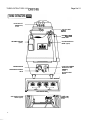
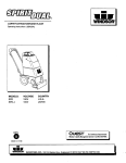
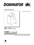
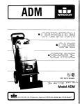
TURBO EXTRACTORS 115V (OBS 10188)
Page 1 of 11
Models TBOI & TB02 (Twin Vac)
WINDSOR INDUSTRIES, INC.
1351 W. STANFORD AVE., ENGLMKMD. co 80110 3 0 9 762-1800 TWX 910-931-0565
TURBO EXTRACTORS 115V (09s 10/88)
Page 2 of 11
TURBO EXTRACTORS
FLOAT SHUT OFF
(TB02 shown)
AUTO FILL INLET
(optlon)
WASTE SOLUTION
DRAIN HOSE
DEFOAMER INJECTOR
(optlon )
SOLUTION INJECTION
METER (option)
OUTLET FOR POWERED
BRUSH FLOOR TOOL
(T602 only)
PRESSUREGAUGE
PRESSURE AOJUSTMENT
VALVE
\
\
SOLUTION OUTLET
NIPPLE
I
[O
1
C’
’
BACK SWITCH PANEL
AUTO PUMP-OUT HOSE
OUTLET (option)
2
I
CIRCUIT
I
t cincun 1
I
POWER CORD
(fB02 shown)
TURBO EXTRACTORS 115V (OBS 10/88)
INSPECTION
Carefully unpack and inspect our Extractor for shipping damage. d c h unit
is operated and thoroughly inspected
before shipment, and any damage is the
responsibility of the delivering carrier,
who should be notified immediately.
ELECTRICAL
The TURBO ONE (single vac machine) is
designed to operate on a standard 20
amp., 115 volt 60 hz household circuit*.
NOTE: The TURBO TWIN (twin vac machine) requires (2) 20 amp., 115 volt
tircuits for maximum erformance.
230 volt 50 hz mode s available.
P
GROUNDING INSTRUCTIONS
To protect the o erator from electrical
shock, this machrne must be grounded
while in use. The machine is equipped
with an approved three-conductor power
cord and three-prong grounding type
plug to fit the proper grounding type
receptacle.
WARNING: To avoid electrical shock, use
indoors only.
Page 3 of 11
8002ss
S W l P R O I 9502 SS
144040
7i
&
8002SS
144045
8002SS
9502 SS
9502 SS
144040
144045
$44040
PRIMING PUMP
If the extractor has been in storage or if
the pump has been run dry, It will be
necessary to prime the pump before starting the cleaning process.
1. Connect prime adapter to outlet nipple
on machine.
2. Connect vac hose from dome to prime
adapter.
3. Switch on vac motor and pump and
run for 5 to 10 seconds, Disconnect
primer adapter from outlet ni ple and
check ressure auge for PSPreading
(200 Pgi) lndicatkg pump has primed.
EXTENSION CORDS
If an extension cord is used, the wire
size must be at least one size larger
than the power cord from the machine
and should be limited to 50 feet in length.
Extension cord must be three-wire
rounded. TBOI is equi ped with a 25 ft.
82-3 power cable. TBO! is equipped with
(2) 25 ft. 12-3 power cables.
PREPARING THE TURBO ONE AND
TWIN
Using a clean bucket, fill solution tank
with hot water. The maximum capaclty
of the TURBO is 17 allon solutlon and
15 gallon recovery.
in a non-foam!ng
concentrate for use in hot water extraction
machines at the proportions as noted on
-the container for various carpet soil conditions. Llquld detergents are preferred.
However, when using a powder cleaner,
premix thoroughly in a clean container
with a gallon of hot water before addin
to solution tank. UNDISOLVED POWDEW
will cause premature wear of pump piston
cups.
CAUTION: Do not put defoamer. solvents,
spotter or prespray chemicals in the solution tank.
CAUTION: When operatin the Turbo at
maximum pressure (200 SI), use only
Hoor tools equipped with metal manifolds
and solution hoses designed to operate
at pressures of 200 PSI or hlgher.
On floor tools not equipped to operate at
above pressures, lower the ressure of
the Turbo as required (See kkmp Pressure Adjustment).
NOTE: Correct jet slze is ver Important
to the operatlon of this macline. When
operating at maximum PSI, use stainless
steel jets on floor tools listed at the top
of next column (squipped with metal
manifolds as noted above).
MBX
PUMP PRESSURE ADJUSTMENT
CAUTION: The maximum pump operating
pressure of 200 PSI is preset at the factory. Do not operate the machine at higher
pressures.
When using hand tools for cleaning upholstery, stairs and edgin , the suggested
pressure is 20 to 35 P81. Higher pressure (35 to 200 PSI) is recommended for
carpet cleaning.
The pressue is adjustable (0 to 200 PSI)
by means of the pressure relief Valve.
To ad st ressure Loosen lock nut turn ande clockwise to increase pressure and counter clockwise to decrease
pressure. Retighten nut after adjusting
pressure.
kP
-
\
REQUIRED CIRCUITS:
The Turbo One is designed to operate on
a standard 20 amp circuit the Turbo
-
Twin requlres (2)20 amp circuits. However the Twin can be operated on a single
20 amp circuit by connectin circuit 1
power cord to outlet and "lockng down"
#2 vac float shut-off. The Twin can also
be operated on (2) 15 amp circuits
(should 20 amp not be available). To do
so: Connect each power cord to separate
15 amp circuit, lock down" #1 vac
float shut-off. Switch on pump (only) in
circuit #1 and vac in circuit #2.
9
Y
.
NOTE: The Turbo Twin (only) is equipped
with a receptacle for connecting a powered
brush floor tool (Pilejogger or Pilemaster).
A strain relief kit with instructions for
attaching to floor tool power cord Is Included with Turbo Twin machine.
CLEANING PROCESS
Determine precisely what areas you are
going to clean. Note problem areas in the
carpet or tack strip. Look for loose carpet, heavily damaged areas, discolored
stains, or grease spots that will require
prespotting. Note the carpet type. Check
the availability of hot water. drains. suitable electrical outlets. If the carpet is
loose or torn, have it repaired before you
start to clean it.
Pian your cleaning route, working from
the most remote area toward the exit.
Try not to travel over the cleaned areas
for water or to dump waste. Furniture
should be moved out away from walls
before cteaning. If replaced on damp
car et, use foil or plastlc protectors
u n i r the legs to prevent possible carpet
staining. If possible, open a!l windows
and doors to speed carpet drying
Plug power cable from machine into
properly grounded wall outlet.
Turn vacuum motor switch on and off to
make sure you have electric power at
machine.
3
TURBO EXTRACTORS 115V (OBS 10188)
Connect vac hose to hose inlet on dome.
Connect solution hose to outlet nipple on
machine by sliding back knurled collar
on female coupler and installing coupler
over nipple. Release collar to lock them
together. Make sure coupler is secured
to avoid leaks.
Start in one corner, depress solution
valve lever full and move backward at a
steady pace: 5 to 30 feet er minute,
cleaning a path at least halrthe length
of the room. Release solution valve lever
approximately 6” before reaching the
end of the pass to insure that cleaning
solution is extracted from carpet.
Make the next cleaning ass beside the
first, overlapping about inch. Continue
cleaning until entire width of area has
been cleaned.
Reverse direction and clean balance of
room.
On heavily soiled carpets or on areas of
high foot traffic, it may be necessary to
use a prespray or tratfic lane cleaner
applied with a separate sprayer. Do not
add presprays to the machine solution
tank. If you use a spotter, follow label
directions exactly. Remove the spotter
With the floor tool when done. Never
Im?any spotter in a carpet - it may
b1e.m 5r brown it permanently.
Shag carpets may require several passes
from different directions, but be careful
not to oversaturate. In these cases, make
several vacuum passes without spray to
extract as much moisture as possible.
CAUTION: As you work, check to see if
there is foam buildup in the recovery
tank. If there is, remove the vacuum
hose from the floor tool and add a little
defoaming solution to the hose while the
vacuum is running. Defoamer can also
be added to the recovery tank, but
never to the solution tank.
Page 4 of 11
be used. A’faucet adapter kit is included to attach hose to various
threaded sink faucets.
2. Place chemical injector hose in detergent bottle. Turn on water source and
adjust the floating ball on the metering valve to required ounce of detergent per gallon of water.
I
CLEANUPANDSTORAGL
Empty solution tank by detaching vacuum
hose at floor tool and placin in solution
tank with vac motor switche on.
P
!
3. Connect standard .5!8 I.D. garden
hose to pump-out fitting. Secure discharge end of hose to waste water
sink or floor drain to prevent dirty
water being spilled outside the dumping area.
CAUTION: KEEP DRAIN CAP secured
to pump-out fitting when discharge
hose is disconnected.
Empty recovery tank directly into floor
drain or bucket for disposal. Flush
inside of both tanks with clean water.
OPERATING TURBOS WITH
(OPTIONAL) AUTO FILL/PUMP-OUT
AND OEFOAMER INJECTOR.
1. Attach auto fill hose (12 ft. nylobraid
hose) to inlet nipple.
F’-
..
&
Clean exterior of machine with mild soap
and warm water. Wipe out recovery dome
and store upside down on recovery tank
to permit drying of inside of tank.
@
The other end of hose has a standard
garden hose connector. Should additional hose be needed to reach water
source a standard garden hose can
4
4. The defoamer injector can be used
should excessive sudsing occur during
c1eaning;operation ..Fill bottle with defoaming agent. With dome in place
and vacuum switched on, open petcock valve to allow just enough defoamer to be siphoned into waste water
tank to control sudsing.
Page 5 of 11
TURBO EXTRACTORS 115V (OBS 10188)
Inspect screens inside of recovery and
solution tanks. Remove and clean with
soft bristled brush and hot soapy water.
PERIODIC MAINTENANCE
At the end of every working day, flush
entire pumping system, including floor
tool, hand tool, etc. with 1 lo 3 gallons
of clean hot water.
NOTE: For infrequent use or long periods
of storage, flush machine with a neutralizing solution ( 1 qt. white vinegar mixed
with 2 gallons hot water) and drain system thoroughly. Solution can be removed
from pump and internal plumbing by
using the prime adapter. Attach prime
adapter to outlet nipple. Connect vac
hose from dome to adapter and switch
on vac motor. Run vac motor for 2 or 3
minutes.
Lubricate quick disconnect hose fitting
with silicone lubricant. Do not use petroleum based lubricants as they will cause
damage to the '0' rings.
Check spray nozzles frequently. If they
become clogged, remove them, wash
thoroughly and blow dry. Do not use pins,
wire, etc. to clean nozzles as this could
destroy spray pattern.
Periodically inspect hoses, electrical
cables, filters and connections on your
machine. Frayed or cracked hoses should
be repaired or replaced to eliminate vacuum or solution pressure loss. Because
the electrical cable will lie on wet carpel
at times, the cable must be well insulated
and cable connector screws kept tight.
If the cable insulation is broken or frayed,
repair or replace it immediately. Don't
take chances with an electrical fire or
shock.
Lubricate wheel bearings monthly with 3
or 4 drops of #lo oil.
Very little grease is required. DO NOT use
an air-powered grease gun, it develo s
too much pressure and will blow out t e
bearing grease seals.
IMPORTANT: Pump cavity should always
be clear of excess grease for proper heat
DO NOT
dissipation. Wipe out grease
wash out.
t
.
1
-
.M
VAC MOTOR
1. Disconnect wires, remove screws holding vac motor(s) to base plate.
SERVICING TBOl AND TB02
CAUTION: Do not make repairs or ad'ustments without disconnecting mac ine
from electrical source.
1,
TANK REMOVAL
1. Remove tank hold-down clip.
2. To inspect brushes, remove metal
wraparound from the vac motor (one
screw). Remove brush told-downs.
New brush length is 1 . Brushes
should be replaced when they reach
318" length, or after 750 operating
hours.
2. Tilt tank forward to expose solution
and vac hose connections on bottom
of tank. Disconnect hoses from tank.
Remove (2) hinge pins and lay tank
aside.
3. Inspect vacuum intake opening for lint.
..
PUMP LUBRICATION
Remove left rear wheel to access plug.
Remove access plug. Lubricate cam
bearing (grease fitting) with moly-lithium
No. 2 rease (wheel bearing grease)
every 1 0 hours of operation or monthly
(whichever is first).
CAUTION: Use a push-type, hand-operated
grease gun if available. If using a leveroperated grease gun work lever VERY
slowly to prevent damaging bearing seal.
oe
-
If there are large accumulations, the
fan section should be disassembled
and cleaned.
NOTE: Vacuum motors can usually be
repaired, but such repairs should always be done by a qualified vacuum
repair shop.
PUMP-OUT PUMP (option)
1. Disconnect wiring, remove (4) screws
holding pump to base plate. Discon-
nect hose from pump head. Refer to
pump-out parts list for replacement
parts.
5
TURBO EXTRACTORS 115V (OBS 10/88)
2. Clean and flush soap residue and lint
from check valve. NOTE: When reinstalling check valve, make sure
arrow on valve is pointed towards
pump inlet.
SOLUTION PUMP
1. Remove solution and recovery tank.
2. Remove vac motor(s).
3. Remove pump-out pump.
4. Remove pump and motor shroud by
removing (6) screws-(3) holding front
of shroud to base plate and (3) located
at rear of lower housing.
I
5.
0
To remove base plate (with pump and
motor attached) remove (6) bolts - (5)
IOQted inside of base housing and (1)
located at rear underside of housing,
Page 6 of 11
SWITCH CONTROL PANEL/MUFFLER
REPLACEMENT
1. Remove screws holding rear panel.
Lift out panel to access switches and
muffler. Replace switch(es) as required. Inspect acoustical foam in
muffler for lint build-up or deterioration
- replace muffler assembly as required.
6. To remove pump from motor - remove (2) set screws holding pump
collar to motor shaft. Refer to manufacturer's service manual for cup replacement and service.
TURBO EXTRACTORS 115V (OBS 10/88)
ELECTRICAL CIRCUIT IDENTIFICATION
TBOP-AF (with options)
Page 7 of 11
TURBO EXTRACTORS 115V (OBS 10/88)
Page 8 of 11
n
0
m
v)
TURBO EXTRACTORS 115V (OBS 10/88)
\
Q
I ?
10
Page 10 of 11
TURBO EXTRACTORS 115V (OBS10/88)
Page 11 of 11
~ _ -_-
TROUBLE SHOOTING GUIDE
PROBLEM
POSSIBLE CAUSE
SOLUTION
Dead 8Ieclrical c i r w ~
Check building orcult breaker or l u a box
Power swlch lailure
Faulty electrual cabla
Replace
RdQlaCS
08drkal shock.
Esuipment nM groundsd
On 3 pronged adapler ba sure ground
wire is secured
Motor ap8id vrhr of dmn't M.
MMw worn-out
flepucs
Loss of vacuum.
Lwze vacuum dome
Cenler and sea d w over lank
Replwc or reseal using Pastlc cement my
With power oll clean screen
righim culls turning WUnIerCIOCkwsC
Repuce
warn out ualh hose RCII linl ouf wtm WIR
Crack in d w or delec!ive glue lmnt
(Jntoi dirl clogging vacuum yrwn.
Loose culfs on vacuum M a
Vacuum motoc smr Ibaking
Flow loo1 uacuum cnamw plugged
BfOkM V X hose .
Damaged dome gasxei
WoIn.ouI vac molor
Corrouon on fmings
ReDlica
mace
kpme
Clean litlings wilh StWI HOOl SO& in
vinegar solution Luoruale lightly with
S I l K O ~lube
NM g8tling cafpel cban.
Ssvere 9oll COndi!mns
Make me than one paas I righl angle
IO
Carptl100 Wll.
lsds listings under lw of vacuum hslding 1
Carpel brownlng
Leaving carpel loo wet
Too much chemical in solu!lan.
Light u r w t with no brown preventmn
Sc4oIuuon problems.
Solution won't shul OH.
SOlUllOn hose quck dumnects.
first pars
C M k vacuum sptem for loss of vacuum
Reduce arnounl 01 chemical Check label
dlfeCllDnS
pmPN CO(ICWlfdtlM
to over carpet witn bIOWningprevent
solutmn only
lklectlve or worn.out pump
Faulty or plugged R e m m 2nd wamne
Replace II nwssary.
Repair or foplaw.
Faulty flwr twl solullon v L e
Maifor repcam
~~~
LIMITED WARRANTY
WINDSOR warrants to the orlglnal
purchaserluser that this product is
free from defects in workmanship
and materlals under normal use and
service for a period of one year from
date of purchase. WINDSOR wlll, at
its option, repair or replace without
charge. except for transportation
costs, parts that fail under normal
use and service when operated and
maintained in accordance with the
applicable operation and instruction manuals. This warranty does
not apply to normal wear, or to
Items whose life Is dependent on
their use and care, such as cords,
switches, hoses, rubber parts.
electric motor parts, etc.
This llmited warranty is In lieu of all
other warranties, ex ressed or lmplied, and releases &iNDSOR from
all other obligations and liabllitles.
It is applicable only in the U.S.A.
and Canada, and Is extended only
to the orl inal userlpurchaser of this
product. bINDSOR is not responsible for costs for repalrs performed
by persons other than those speclflcally authorlzed by WINDSOR. This
warranty does not apply to dama e
from transportation, alterations gy
unauthorized persons, misuse or
abuse of the equipment, use of noncompatible chemlcals, or damage
to property, or loss of income due
to malfunctloning of the product.
If a difficulty develops with this
machine, you should contact the
dealer from whom it was purchased.
11