1
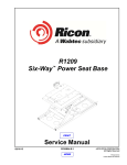
® INNOVATION IN MOBILITY ™ RDO2500 Series Power Sliding Door Operator PRINT Service Manual 02/14/02 32DDO02.A U.S. Patent Nos 5,613,321; 5,794,381 Other U.S. and foreign patents pending Printed in the United States of America 1992-02 RICON CORPORATION All Rights Reserved This Ricon service manual is for use by qualified service technicians, and is not intended for use by nonprofessionals (do-it-yourselfers). The manual provides essential instructions and reference information, which supports qualified technicians in the correct installation and maintenance of Ricon products. Qualified service technicians have the training and knowledge to perform maintenance work properly and safely. For the location of a Ricon authorized service technician in your area, call Ricon Product Support at 1-800-322-2884. Customer Name: Installing Dealer: Date Installed: Serial Number: 32DDO02.A i REVISION RECORD REV PAGES 32DDO02 .A All DESCRIPTION OF CHANGE New release, in two-book format. END OF LIST ii 32DDO02.A ECR/ECO 3882/4864 TABLE OF CONTENTS Page Chapter: I. INTRODUCTION ................................................................................................................................ 1-1 A. B. C. D. RICON ONE-YEAR LIMITED WARRANTY ..................................................................................................... 1-1 SHIPMENT INFORMATION ............................................................................................................................. 1-3 GENERAL SAFETY PRECAUTIONS............................................................................................................... 1-3 COMPONENT TERMINOLOGY ....................................................................................................................... 1-4 II. INSTALLATION ................................................................................................................................. 2-1 A. MECHANICAL INSTALLATION........................................................................................................................ 2-1 1. VAN PREPARATION .................................................................................................................................2-1 2. DOOR OPERATOR INSTALLATION.........................................................................................................2-1 3. FORWARD DOOR BRACKET INSTALLATION ........................................................................................2-1 4. CHAIN HOOK INSTALLATION..................................................................................................................2-1 5. CHAIN ASSEMBLY....................................................................................................................................2-2 B. ELECTRICAL INSTALLATION ......................................................................................................................... 2-2 C. INSTALL COVER ............................................................................................................................................. 2-2 D. VERIFY INSTALLATION .................................................................................................................................. 2-2 E. CUSTOMER ORIENTATION ............................................................................................................................ 2-2 III. MAINTENANCE ................................................................................................................................. 3-1 A. MAINTENANCE SCHEDULE ........................................................................................................................... 3-1 B. TROUBLESHOOTING GUIDE ......................................................................................................................... 3-2 C. ELECTRICAL WIRING DIAGRAMS ................................................................................................................. 3-3 1. DIAGRAM LEGEND...................................................................................................................................3-3 2. WIRING DIAGRAM ....................................................................................................................................3-5 IV. PARTS DIAGRAMS AND LISTS ....................................................................................................... 4-1 32DDO02.A iii This page intentionally left blank. iv 32DDO02.A I. INTRODUCTION T he RICON RDO2500 Series Power Sliding Door Operator opens and closes sliding van doors. It has been designed to operate in most full-size vans and works in conjunction with Ricon S-Series, Spirit, and UNI-lite Wheelchair Lifts. The power door operator is electrically connected to, and is operated with, the controls of the wheelchair lift or ramp. As the lift is activated to DEPLOY (extend from the vehicle), the power door operator automatically opens the vehicle door to allow the lift to deploy. The door operator automatically closes the vehicle door after the platform has been retracted into the vehicle. This manual contains installation, maintenance instructions, and spare parts for the power door operator. The installation instructions must be followed exactly, no steps should be eliminated, nor should the product be modified. It is important to user safety that the installation is thorough and correct. It is equally important that the Ricon sales/service staff be completely familiar with the Operators manual to demonstrate and explain the proper use of the product to the user. Once the door operator is installed, it is very important that it be properly maintained by following the Ricon recommended cleaning, lubrication, and inspection instructions. If there are questions about this manual, or additional copies are needed, please contact Ricon Product Support at one of the following locations: Ricon Corporation 7900 Nelson Road Panorama City, CA 91402 ...........................................................................................................(818) 267-3000 Outside (818) Area Code.............................................................................................................(800) 322-2884 World Wide Website.......................................................................................................... www.riconcorp.com Ricon U.K. Ltd. Littlemoss Business Park, Littlemoss Road Droylsden, Manchester United Kingdom, M43 7EF ...................................................................................................(+44) 161 301 6000 A. RICON ONE-YEAR LIMITED WARRANTY (refer to following page) 32DDO02.A 1-1 RICON CORPORATION ONE-YEAR LIMITED WARRANTY Ricon Corporation (Ricon) warrants to original purchaser of this product that Ricon will repair or replace, at its option, any part that fails due to defective material or workmanship as follows: • Repair or replace parts for a period of one year from date of purchase. If you need to return a product: Return this Ricon product to your installing dealer. Please give as much advance notice as possible and allow a reasonable amount of time for repairs. If you are traveling: All authorized Ricon dealers honor this warranty. Consult telephone directory or call our Product Support department for the name of the nearest authorized Ricon dealer. This warranty does not cover: § Labor or service charges (these may be covered separately by the installing dealer). § Malfunction or damage to product parts caused by accident, misuse, lack of proper maintenance, neglect, improper adjustment, modification, alteration, the mechanical condition of vehicle, road hazards, overloading, failure to follow operating instructions, or acts of Nature (i.e., weather, lightning, flood). Note: Ricon recommends this product be inspected by an authorized Ricon service technician at least once every six months, or sooner if necessary. Any required maintenance should be performed at that time. WARNING! THIS PRODUCT HAS BEEN DESIGNED AND MANUFACTURED TO EXACT SPECIFICATIONS. MODIFICATION OF THIS PRODUCT IN ANY RESPECT CAN BE DANGEROUS. This Warranty is Void if: • The product has been installed or maintained by someone other than an authorized Ricon service technician. • The product has been modified or altered in any respect from its original design without written authorization by Ricon. Ricon disclaims liability for any personal injury or property damage that results from operation of a Ricon product that has been modified from the original Ricon design. No person or company is authorized to change the design of this Ricon product without written authorization by Ricon. Ricon's obligation under this warranty is exclusively limited to the repair or exchange of parts that fail within the applicable warranty period. Ricon assumes no responsibility for expenses or damages, including incidental or consequential damages. Some states do not allow the exclusion or limitation of incidental or consequential damages, so the above limitation or exclusion may not apply. Important: The warranty registration card must be completed and returned to Ricon within 20 days after installation of this Ricon product for the warranty to be valid. The warranty is not transferable. The warranty gives specific legal rights, and there may be other rights that vary from state to state. 1-2 32DDO02.A B. SHIPMENT INFORMATION Ricon does not sell directly to the user because of the specialized nature of this product. The product is distributed through a worldwide network of authorized Ricon dealers who perform the actual installation. Be sure installation kit contains all items listed on kit packing list. Please report any missing items immediately to Ricon Product Support. The warranty and owner registration cards must be completed and returned to Ricon within 20 days for the warranty to be valid. The Sales/Service Personnel must review the Warranty and this Operator Manual with user to be certain that they understand safe product operation. Instruct the user to follow operating instructions without exception. C. GENERAL SAFETY PRECAUTIONS The following general safety precautions must be followed during installation, operation, service, and maintenance: • Under no circumstances should installation, maintenance, repair, or adjustments be attempted without the immediate presence of a person capable of rendering aid. • An injury, no matter how slight, must be attended. Administer first aid or seek medical attention immediately. • Protective eyeshields and appropriate clothing should be worn at all times. • Avoid injury; exercise caution when using door operator and be certain that hands, feet, legs, and clothing are out of the path of the moving door and lift. • Batteries contain acid that can burn. If acid comes in contact with skin, immediately flush affected area with water and wash with soap. • Always work in a properly ventilated area. Do not smoke or use an open flame near battery. • Do not lay anything metallic on top of battery. • Check under vehicle before drilling to avoid damaging the frame, subframe members, wiring, hydraulic lines, fuel lines, fuel tank, etc. • Read and thoroughly understand the operating instructions before attempting to use door operator. • Inspect the product for any unsafe condition before using. If unusual noise or movement is present, do not use product until the problem is corrected. • Keep others clear during operation. The product requires regular periodic maintenance. A thorough inspection is recommended at least once every six months. The product should be maintained at the highest level of performance. 32DDO02.A 1-3 D. COMPONENT TERMINOLOGY The references used throughout this manual are illustrated in Figure 1-1 and defined in Table 1-1. Refer to Service Manual, Chapter IV, “Spare Parts” for more details. FIGURE 1-1: RDO2500 POWER DOOR OPERATOR COMPONENTS TABLE 1-1: RDO2500 SERIES COMPONENT TERMS REF NAME DESCRIPTION 1 Gearmotor Opens and closes the vehicle door. 2 Main plate Mounts the door operator assembly securely to the vehicle door. 3 Exit rollers Routes chain to and from gearmotor. 4 Clutch release handle Engages and disengages the clutch assembly. Clutch assembly Disengages gearmotor sprocket from gearmotor, allowing free rotation of the gear sprocket and easier manual operation of the vehicle door. Cover Houses the door operator assembly. 5 6 END OF TABLE 1-4 32DDO02.A II. INSTALLATION T he chapter provides instructions for installing the RICON RDO2500 Series Power Sliding Door Operator into most full-size vans. Custom installations are possible in other types of vehicles. Please contact Ricon Product Support for assistance if a question arises that is not covered here; it is impractical to provide specific information in this manual for every possible application. CAUTION! This Ricon product requires a precise installation. The product must be installed by a trained, authorized Ricon service technician. The following instructions explain the four basic steps for installing the power door operator: A. Mechanical B. Electrical C. Install cover D. Installation verification A. MECHANICAL INSTALLATION 1. VAN PREPARATION a. Safely park van on a flat, level surface and turn off engine. b. The power door operator must be attached directly to the metal of the vehicle. Remove existing door panels, interfering carpet, plywood, molding, wall paneling, etc. Clear area of all loose material. WARNING! § § § WEAR PROTECTIVE CLOTHING AND EYE PROTECTION AT ALL TIMES. BATTERIES CONTAIN ACID THAT CAN BURN. IF ACID COMES INTO CONTACT WITH SKIN, IMMEDIATELY FLUSH AFFECTED AREA WITH WATER AND WASH WITH SOAP. DO NOT SMOKE OR USE OPEN FLAME IN THE VICINITY OF BATTERY. ALWAYS WORK IN A PROPERLY VENTILATED AREA. DO NOT LAY ANYTHING METALLIC ON TOP OF BATTERY. c. At vehicle engine compartment, disconnect the positive cable from the battery. d. With the door closed, check the clearance between the side of the van door and the van body. Verify that the clearances at the right and left side of the door are the same width. Door should operate freely and easily before installing door operator. e. Drill mounting holes as specified in the Installation Instructions provided with the Power Door Operator kit. 2. DOOR OPERATOR INSTALLATION Refer to the Installation Instructions provided in the Power Door Operator kit for information pertaining to your particular vehicle make and model. 3. FORWARD DOOR BRACKET INSTALLATION a. Position the forward door bracket as shown in the Installation Instructions and, using the bracket as a template, mark the mounting hole locations. NOTE: Be certain that the roller on the forward door bracket assembly is properly aligned vertically with the exit roller of the Power Door Operator. If not aligned properly, the chain will create excessive noise. b. Center-punch the mounting hole locations, then drill the mounting holes (see Installation Instructions). c. Install the forward door using the three #8 Phillips-head sheetmetal screws provided. 4. CHAIN HOOK INSTALLATION Refer to the Installation Instructions provided in the Power Door Operator Kit for information pertaining to your particular vehicle make or model. 32DDO02.A 2-1 5. CHAIN ASSEMBLY a. Route chain inside the vehicle, passing it through the Delrin bushing previously installed in the interior door panel (see Installation Instructions). b. Refer to Figure 2-1. Route chain around three rollers and spur gear. c. Close sliding door completely and route chain around roller on the forward door bracket and door operator rollers. Be certain not to twist chain between the forward door bracket and door operator rollers. d. Refer to Figure 2-2. Once the chain has been routed around the forward door bracket roller, pull chain FIGURE 2-1: CHAIN ASSEMBLY DETAIL toward the sliding door and install washer over the chain. e. While maintaining a taut pull on the chain, insert the forward, hook-end of the spring through the chain link behind the washer. f. Attach the rear, hook-end of spring through eyelet on the forward door bracket. B. FIGURE 2-2: WASHER INSTALLATION ON CHAIN ASSEMLBY ELECTRICAL INSTALLATION Refer to the Installation Instructions provided in the power door operator kit for information pertaining to your particular vehicle make/model. C. INSTALL COVER 1. Insert release pin from inside to outside and insert clip to secure it (see Installation Instructions). 2. Place cover over power door operator and secure using supplied screws. D. • • • E. VERIFY INSTALLATION Be certain there is no interference with operation of the door operator by interior or exterior components. Verify proper manual operation of door operator. Ensure that the serial number decal is properly located and affixed to the power door operator. CUSTOMER ORIENTATION IMPORTANT - Customer Orientation Ricon Sales/Service Personnel must review the Warranty and Operator Manual with the customer to be certain they understand safe operation of the equipment. Instruct the customer to follow the operating instructions without exception. 2-2 32DDO02.A III. MAINTENANCE R egular maintenance of the RICON RDO2500 Series Power Sliding Door Operator will provide optimum performance. During the Ricon warranty period, maintenance inspections must be performed by an authorized Ricon service technician at least once every six months, or sooner depending on usage. After the warranty period, maintenance inspections are recommended at the same intervals. CAUTION! This Ricon product is highly specialized. Maintenance must be performed by an authorized Ricon service technician using Ricon replacement parts. Modifying or failing to properly maintain this product will void the warranty and may result in unsafe operating conditions. To maintain the warranty, this product must be inspected at least every six months, or sooner depending on usage. A. MAINTENANCE SCHEDULE TABLE 3-1: PERIODIC MAINTENANCE 6 MONTHS OF OPERATION Check and clean chain and rollers. Lightly oil as needed. Check door motion for complete travel. Adjust as needed. Check all fasteners for tightness. Tighten as needed. Check crossover harness for interference with moving members. Adjust as needed. Check manual operation of power door operator per instructions in the Operator Manual, Chapter II. Verify proper operation. REMOVE DOOR PANELS Check spur gear and bushings for signs of wear. Replace if needed. Check wiring and limit switches for proper connection and/or interface points. Adjust as required. END OF TABLE 32DDO02.A 3-1 B. TROUBLESHOOTING GUIDE The troubleshooting guide is designed to provide a logical starting point to locate general problems that could occur with the door operator. However, not all possible problems or combinations of problems are listed. The guide does not incorporate routine safety precautions or preliminary procedures and assumes that the vehicle battery is fully charged and the battery terminals are clean and tight. WARNING! THE TROUBLESHOOTING GUIDE DOES NOT INCORPORATE ROUTINE SAFETY PRECAUTIONS OR PRELIMINARY PROCEDURES. DURING THE RICON WARRANTY PERIOD, AN AUTHORIZED RICON SERVICE TECHNICIAN MUST PERFORM TROUBLESHOOTING. AFTER THE WARRANTY PERIOD, IT IS RECOMMENDED THAT TROUBLESHOOTING CONTINUE TO BE PERFORMED BY AN AUTHORIZED RICON SERVICE TECHNICIAN. TABLE 3-2: TROUBLESHOOTING GUIDE SYMPTOM NO OPERATION OPEN MOTION CLOSE MOTION No power to door operators POSSIBLE CAUSE Battery terminals dirty. Clean/tighten. Ground connection. Clean/repair. Battery defective. Replace. Battery discharged. Check battery capacity; charge battery. Circuit breaker defective. Check 30 amp circuit breaker for short in power wire or replace. Power to switches only Switch defective. Replace. Loose connection. Repair. No motion Toggle switch defective. Replace. Wiring connection. Clean/repair. Limit switch at right door defective. Replace. Motor defective. Replace. Poor ground connection. Repair. Toggle switch defective. Replace. Wiring connection. Repair. Limit switch at left door defective. Replace. Left motor defective. Replace. Ground connection. Clean/repair. No motion END OF TABLE 3-2 REMEDY 32DDO02.A C. ELECTRICAL WIRING DIAGRAM 1. DIAGRAM LEGEND a. Color Codes TABLE 3-3: COLOR CODE DEFINITIONS CODE COLOR CODE COLOR BK Black R Red BL Blue VI Violet BR Brown VI/BK Violet w/black GN Green W White GN/BK Green w/black W/O White w/orange O Orange Y Yellow O/BK Orange w/black Y/BK Yellow w/black END OF TABLE b. Connectors Refer to Figure 3-1. The standard electrical connectors used by Ricon are Molex .062" Series. These connectors have terminal numbers stamped onto the rear. Use these numbers and colors to identify all wires. FIGURE 3-1: MOLEX CONNECTORS wires. c. Labels 32DDO02.A 3-3 d. Symbols FIGURE 3-2: DIAGRAM SYMBOLS 3-4 32DDO02.A 2. WIRING DIAGRAM FIGURE 3-3: RDO2500 ELECTRICAL WIRING DIAGRAM 32DDO02.A 3-5 This page intentionally left blank. 3-6 32DDO02.A IV. SPARE PARTS T his chapter contains parts diagrams and lists for the RICON RDO2500 Series Power Sliding Door Operator. The diagrams are exploded views of lift components with individual components referenced by numbers. Each accompanying parts list contains the part reference number, description, quantity used, and the Ricon stock number. For parts identification, locate the part on the appropriate drawing and note the reference number. The parts list that accompanies each drawing will list the stock number of the desired part. PRODUCT MODEL AND KIT NUMBERS PRODUCT NUMBER RDO2501, RDO2502, RDO2503, RDO2504, & RDO2505 DOCUMENTATION KIT NUMBER 01278 SPARE DECAL KIT NUMBER 26000 32DDO02.A 4-1 FIGURE 4-1: POWER DOOR OPERATOR RDO2500 SERIES 4-2 32DDO02.A FIGURE 4-1: POWER DOOR OPERATOR RDO2500 SERIES SERIAL No's. 250001 and HIGHER REF. DESCRIPTION QTY PART NO. 1 2 3 4 5 MS 10-24 X 3/8 PHIL PAN COVER, DOOR OPENER SOC. BUTTON HD. 5/16-18X2 ROLLER, SLIDER .38 ID X .72 L BOLT-SHOULDER 3/8X3/4 4 1 3 2 2 28109 R25-0003 28146 01511 28377 6 7 8 9 10 BRACKET, MAIN MOTOR MOUNTING CLAMP NYLON 5/16, BLACK MOTOR ASSY RELAY, MODIFIED BLOCK, SUPPORT, MOTOR BRACKET 1 1 1 2 1 R25-0001 28-02-351 V2-ES-040 R25-0005 R25-0007 11 12 13 14 15 NUT-HEX 5/16-18 NYLON INSERT SPRING, COMPRESSION-0.297 OD X 0.75 WASHER, DELRIN, CLUTCH SPROCKET, CLUTCH ASSEMBLY, MECH-CLUTCH, PIN AND PLATE 2 1 1 1 1 28314 254524 R25-0106 R25-0105 R25-0115 16 17 18 19 20 CLIP, RETAINER SPRING ROLLPIN, 1/8 X 1 SST ASSEMBLY, WELD-LEVER, CLUTCH SLEEVE, CLUTCH BRACKET, SUPPORT CLUTCH 1 2 1 1 1 R25-0107 28354 R25-0123 R25-0103 R25-0101 21 22 SPRING, FLAP LATCH PIN DECAL, PATENT # ; DOOR OPERATORS 1 1 25442 32-10-174 32DDO02.A 4-3 This page intentionally left blank. 4-4 32DDO02.A ®