1
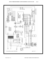
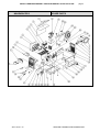
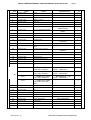
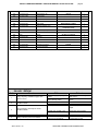
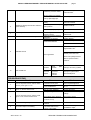
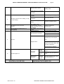
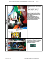
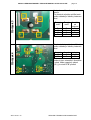
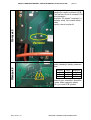
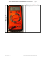
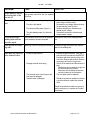
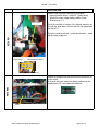
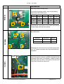
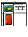
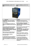
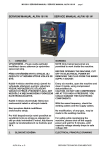
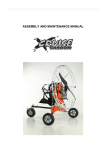
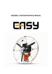
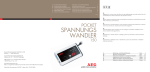
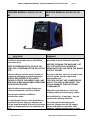
MG022-2 SERVISNÍ MANUÁL / SERVICE MANUAL ALFIN 160-161 MF
page 1
SERVISNÍ MANUÁL ALFIN 160-161
MF
SERVICE MANUAL ALFIN 160-161
MF
1.
VAROVÁNÍ
UPOZORNĚNÍ – Pouze osoba splňující
kvalifikaci danou zákonem je oprávněna
opravovat stroj.
WARNING
NOTE Only trained personnel are
permitted to work inside the machine.
PŘED OTEVŘENÍM KRYTU STROJE JEJ
ODPOJTE VYTAŽENÍM SÍŤOVÉ VIDLICE ZE
SÍTĚ.
Každé 4 měsíce otevřete stroj a jemně ho
vyfoukejte stlačeným suchým vzduchem
POZOR, NEPOUŽÍVEJTE STLAČENÝ
VZDUCH O PŘÍLIŠ VYSOKÉM TLAKU, ABY
NEDOŠLO K MECHANICKÉMU POŠKOZENÍ
ELEKTROSOUČÁSTEK.
Každé 4 měsíce zkontrolujte řádný stav
svařovacích kabelů a síťových kabelů.
Není povolena žádná modifikace
svařovacího stroje.
Pro Vaši bezpečnost je nutné posečkat se
sundáním krytu ze stroje po odpojení ze
sítě po dobu minimálně 5 minut, kdy klesne
napětí na kondenzátorech na hodnotu pod
36 V.
ALFA IN a. s. ©
BEFORE OPENING THE MACHINE, CUT
OFF ITS ELECTRICAL POWER BY
REMOVING THE PLUG FROM THE MAINS
SUPPLY SOCKET.
Every six months, open the machine and
clean it inside, using compressed
dehumidified air.
CAUTION. DO NOT USE COMPRESSED
AIR AT TOO HIGH A PRESSURE. YOU
COULD DAMAGE THE ELECTRONIC
COMPONENTS.
With the same frequency, check the
welding cables and the supply cables.
No modification, of any type, may be
made to the welding machine.
For safety while maintaining the
machine, please shut off the supply
power and wait for 5 minutes, until
capacity voltage already drops to safe
SERVISNÍ TECHNICKÁ DOKUMENTACE
MG022-2 SERVISNÍ MANUÁL / SERVICE MANUAL ALFIN 160-161 MF
page 2
voltage 36V.
2.
BLOKOVÉ SCHÉMA
ALFA IN a. s. ©
ELECTRICAL PRINCIPLE DRAWING
SERVISNÍ TECHNICKÁ DOKUMENTACE
MG022-2 SERVISNÍ MANUÁL / SERVICE MANUAL ALFIN 160-161 MF
ALFA IN a. s. ©
page 3
SERVISNÍ TECHNICKÁ DOKUMENTACE
MG022-2 SERVISNÍ MANUÁL / SERVICE MANUAL ALFIN 160-161 MF
3.
NÁHRADNÍ DÍLY
ALFA IN a. s. ©
page 4
SPARE PARTS
SERVISNÍ TECHNICKÁ DOKUMENTACE
MG022-2 SERVISNÍ MANUÁL / SERVICE MANUAL ALFIN 160-161 MF
Poz.
CODE
Název
1
005.0001.0008
Popruh
2
011.0001.0181
Kryt
3
0150001.0001
4
page 5
DESCRIPTION
BELT
ks
1
CASE
1
Chladič l = 107mm
DISSIPATER L=107mm
1
015.0001.0002
Chladič l = 50mm
1
5
012.0001.0000
Vnitřní rám
DISSIPATER L=50mm
INTERNAL FRAMEWORKS
6
050.005.0001
PCB – silová A160MF
POWER BOARD
1
7
046.0004.0004
Isolační deska
1
8
012.0001.0001
Nylonová základní deska krátká
9
045.0005.0006
Bočník
POWER BOARD
INSULATION
SHORT BLACK NYLON
BASE
SHUNT
10
011.0010.0005
Držák přední
FRONT SUPPORT
1
11
050.5052.0001
PCB řídící ALFIN 161
FRONT PANEL
1
12
014.0001.0004
Ovládací knoflík
2
13
711P001004
Rychlost. 10-25 panel
COVER AND HANDLE WITH
POINTER
FIXED SOCKET 200A
14
021.0004.3360
Ovládac. konektor hořáku vidlice
TORCH CONNECTOR
1
15
050.0001.0042
Konektor hořáku - zásuvka
1
16
AO-20501
Rychlospo. 10-25 kabel
TORCH CONNECTOR
BOARD
MOVABLE PLUG 200A
17
012.0004.0010
Přední plastový rám
FRONT
1
18
017.0002.0806
Hadice plynová
GAS PIPE
1
19
040.0003.1080
Termostat tepelné ochrany
THERMAL CUT-OUT
1
20
BG-90625
Konektor EURO
EURO SOCKET
1
21
3494
Posuv CMS100-4 9900006 0608
WIRE DRAWING MOTOR
1
1
1
1
2
1
2087
Kladka prům. 40/22;
0,6-0,8mm; drážka V
ROLLER Ø=40 0,6 –
0,8mm GROOVE V
1
2088
Kladka prům. 40/22;
0,8-1,0mm; drážka V
ROLLER Ø=40 0,8 –
1,0mm GROOVE V
1
2247
Kladka prům. 40/22;
0,8-1,0mm; drážka U
ROLLER Ø=40 0,8 –
1,0mm GROOVE U
1
2317
Kladka prům. 40/22;
0,8-1,0mm; pro trubič.
drát
22
23
041.0005.0004
Pomocný transformátor
24
016.0009.0001
Nožka gumová
25
011.0010,0007
Rám
26
011.0010.0008
27
28
29
1
AUXILIARY TRANSFORMER
1
RUBBER FOOT
4
BASE
1
Držák silové části
POWER SUPPORT
1
015.0001.0004
Chladič l = 75mm
DISSIPATER L=75mm
1
032.0002.0255
Izotop dioda
ISOTOPE DIODE
1
050.0001.0021
PCB regulace otáček
MOTOR BOARD
1
30
011.0010.0003
Vnitřní deska
INTERNAL PLATE
1
31
011.0006.0050
Držák cívky drátu K200
K200 SPOOL SUPPORT
1
32
050.0001.0033
PCB double A150
DOUBLER BOARD
1
ALFA IN a. s. ©
SERVISNÍ TECHNICKÁ DOKUMENTACE
MG022-2 SERVISNÍ MANUÁL / SERVICE MANUAL ALFIN 160-161 MF
4.
33
011.0010.0006
Zadní postranní panel
34
012.0004.0100
Zadní plastový rám
35
017.0001.5542
Plynový ventil
36
013.0007.0200
Panel zadní
37
045.0000.0001
Kabelová průchodka
38
045.0002.0001
39
REAR SIDE PANEL
1
BACK
1
SOLENOID VALVE
1
REAR PANEL
1
CABLE GRIP
1
Síťový kabel
NEOPRENE CABLE
1
021.0000.0000
Sada pro připojení plynu
1
40
040.0001.0001
Vypínač dvoupólový
KIT FOR GAS
CONNECTORS
TWO-POLE SWITCH
41
0500001.0003
PCB - snubber
SNUBBER BOARD
1
42
2681
Zámek
SLIDE CLOSURE
2
43
012.0000.0001
Kryt cívky
K200 SPOOL COVERS
1
44
2911
Ventilátor
FAN
1
45
2686
Plastový pant
PLASTIC HINGE
2
46
011.0000.0201
Otevírací kryt posuvu
DOOR
1
47
042.0003.0001
Silový transformátor
TRANSFORMER
1
ZÁVADY - ŘEŠENÍ
Poř.
Závada
1
page 6
Stroj je zapnutý, ventilátor funguje, LED
zapnutí nesvítí
2
Stroj je zapnutý, LED zapnutí svítí,
ventilátor neběží.
3
Stroj je zapnutý, LED zapnutí nesvítí,
ventilátor neběží.
4
Žádné napětí na prázdno
5
Žádný svařovací proud na svorkách
ALFA IN a. s. ©
Příčina
LED nebo její připojení je
vadné.
Silová PCB je vadná.
Překážka rotace ventilátor.
Motor ventilátor poškozen.
Není napětí v síti
1
Řešení
Opravte připojení nebo vyměňte
LED poř.č11
Opravte nebo vyměňte PCB
poř.č6
Odstraňte
Vyměňte ventilátor
Zkontrolujte, jestli je v síti
napětí.
Přepětí nebo podpětí v síti.
Zkontrolujte síťové napětí.
Závada generátor.
Svařovací kabely nejsou
připojeny do konektorů.
Zkontrolujte hlavní vypínač
Připojte svařovací kabely do
rychlospojek na stroji.
SERVISNÍ TECHNICKÁ DOKUMENTACE
MG022-2 SERVISNÍ MANUÁL / SERVICE MANUAL ALFIN 160-161 MF
Poškozený svařovací kabel.
Zemnící kabel není připojen
nebo je špatně připojen.
Špatně utažené svařovací
kabely.
Svařenec je znečištěn olejem
6
7
8
Obtížně se zapaluje oblouk nebo dochází k
lepení elektrody.
Svařovací proud nelze nastavit.
Penetrace tavné lázně nedostačující.
nebo prachem.
page 7
Vyměňte nebo opravte
svařovací kabel.
Zkontrolujte zemnící kabel
Zkontrolujte utažení
svařovacích kabelů.
Očistěte svařenec.
MMA/TIG výběr je špatný.
Vyberte MMA svařování.
Poškozený potenciometr
předního panelu.
Svařovací proud je nastaven
příliš nízko.
Nepříznivý vliv průvanu
Opravte nebo vyměňte
potenciometr.
Zvyšte svařovací proud
Použijte zástěnu.
Změňte úhle uchycení elektroda
Excentrická elektroda
Vyměňte elektrodu
Nahněte elektrodu proti směru
magnetického vlivu.
9
Nestabilní oblouk
Změňte pozici zemnícího
Vliv magnetismu
kabelu nebo přidejte zemnící
kabel na opačnou stranu
svařence.
10
Stroj
zatížen
Ochrana
přepětí
Nestandardní
proud na
hlavním
obvodu.
LED ALARM svítí
TROUBLESHOOTING
S/N
Troubles
1
Přehřátí
Turn on the power source, and fan works,
but the power light is not on.
2
Turn on the power source, and the power
light is on, but fan doesn’t work
3
Turn on the power source, and the power
light is not on, and fan doesn’t work
příliš
Počkejte, až se stroj vychladí
Otestujte a opravte hlavní
obvod PCB poř.č6
Reasons
The power light damaged or
connection is not good
Power PCB failures
There is something in the fan
The fan motor damaged
No input voltage
Solutions
Test and repair the inside
circuit of power light s/n 6
Repair or change power PCB
s/n 11
Clear out
Change fan motor
Check whether there is input
voltage
Overvoltage (Input voltage is
Check input voltage
too much or not)
4
No no-load voltage output
5
No current output in the welding
ALFA IN a. s. ©
There is trouble inside the
machine
Welding cable is not
connected with the two
output of the welder.
Check the power switch
Connect the welding cable to
the welder’s output
SERVISNÍ TECHNICKÁ DOKUMENTACE
MG022-2 SERVISNÍ MANUÁL / SERVICE MANUAL ALFIN 160-161 MF
Welding cable is broken
Earth cable is not connected
or loosen
The plug loosen or connect
not well
Oil or dust covered the
6
Not easy to start arc in the welding, or easy
to cause sticking
workpiece
MMA/TIG welding selection is
wrong
7
The welding current can not be
adjusted
8
The penetration of molten pool is not
enough(MMA)
The welding current
potentiometer in the front
panel connection not so good
or damaged
The welding current adjusted
too low
Airflow disturbance
page 8
Wrap, repair or change the
welding cable
Check the earth clamp
Check and tighten the plug
Check and clear out
Selecting the MMA welding
Repair or change the
potentiometer
Increase the welding current
Use the shelter from airflow
Adjust the electrode angle
The electrode eccentricity
Change the electrode
Incline the electrode to the
opposite way of the magnetic
9
Arc blow
blow
Magnetic effect
Change the position of earth
clamp or add earth cable in the
two side of workpiece
Use the short arc operation
Over heat
protection
10
The alarm light is on
Over current
protection
5.
KONTROLA SILOVÉ PCB
ALFA IN a. s. ©
Over
welding
current
Working
time too
long
Unusual
current in
the main
circuit
Induce the welding current
output
Induce the duty cycle (interval
work)
Test and repair the main circuit
and drive PCB s/n 6
CHECKING THE POWER PCB
SERVISNÍ TECHNICKÁ DOKUMENTACE
MG022-2 SERVISNÍ MANUÁL / SERVICE MANUAL ALFIN 160-161 MF
page 9
Obrázek 2
Obrázek 1
Pozice kontaktů v konektoru
• teplotní čidlo (žluté dráty): pozice
2,5
• drát pro snímání výstupního
napětí (červený): pozice 3
• dráty bočníku: pozice 1,4
ALFA IN a. s. ©
Zkontrolujte spojení kontaktů
tepelné ochrany pomocí testeru
diod, teplota chladiče nesmí být
vyšší než 40° C.
Zkontrolujte spojení mezi: +
objímkou a červeným drátem
Zkontrolujte průchodnost mezi: objímkou a vodiči bočníku.
Na PCB RC filtr, umístěné nad
výstupním usměrňovačem jsou
umístěny dva transily, Pro kontrolu
musí v obou směrech vykázat
přerušený obvod OL
SERVISNÍ TECHNICKÁ DOKUMENTACE
MG022-2 SERVISNÍ MANUÁL / SERVICE MANUAL ALFIN 160-161 MF
page 10
Obrázek 3
Vstupní usměrňovač na silové
desce
Pro kontrolu můstku změřte tento
podle následující tabulky testerem
diod
Červený
vodič
Černý
vodič
F+
D
D
F-
D
F+
FD
Naměře
ná
hodnota
OL
>0.450
OL
>0.450
Obrázek 4
Pro kontrolu tranzistorů změřte tyto
podle následující tabulky testerem
diod
ALFA IN a. s. ©
červený
S
G
černý
G
S
hodnota
0,28
0,6
Hodnoty jsou orientační. Naměříteli zkrat, nebo rozpojený obvod
(OL), je nutné PCB vyměnit
SERVISNÍ TECHNICKÁ DOKUMENTACE
MG022-2 SERVISNÍ MANUÁL / SERVICE MANUAL ALFIN 160-161 MF
page 11
Obrázek 5
Varistor je blízko vstupu
napájecího napětí na silovou PCB.
Toto zařízení slouží k ochraně PCB
před vstupním
přepětím. Při přepětí "exploduje" a
zkratuje vstup. Je-li rozsah zkratu
velmi
vysoký, obvod se přeruší
Obrázek 6
Pro kontrolu tranzistor změřte
podle následující tabulky testerem
diod
ALFA IN a. s. ©
červený
G
D
G
černý
D
S
S
hodnota
0,5
OL
0,6
Hodnoty jsou orientační. Naměříteli zkrat, nebo rozpojený obvod
(OL), je nutné PCB vyměnit
SERVISNÍ TECHNICKÁ DOKUMENTACE
MG022-2 SERVISNÍ MANUÁL / SERVICE MANUAL ALFIN 160-161 MF
page 12
Obrázek 7
Digitální multimetr. "OL" označuje
přerušený obvod
ALFA IN a. s. ©
SERVISNÍ TECHNICKÁ DOKUMENTACE
161 MF— 161 MTM
!"#$%&'(
'(
PROBLEM
The machine does not
switch on.
)*+,-*( ./--0123( ,45( /20( 6,-7( ,2( 58*( 9/.812*(
9/7*( :4-*( 15( 1:( ,++( /2;( 58*( <=43( 8/:( >**2( ;1:?
.,22*.5*;@(
CASE
Electrical power does not reach the machine.
SOLUTION
!
!
Voltage reaches the machine switch but
there is no voltage after the contacts.
There is voltage after the disconnecting
switch but the machine does not go on.
The protection devices
of the line set off when
the switch is activated
and the machine does
not go on.
Damaged power supply cable with shortcircuited wires.
Inverter is damaged.
Ultima modifica/Last Update: 18/03/2008 Rev0
!
!
!
Make sure the line switches are closed, the
protection devices (fuses) have not been
enabled and that the power supply cable is
intact.
Switch the machine off and disconnect the
plug. Make sure that when the switch is
closed, there is continuity between the
contact input and output and that the varistor is not broken. In case the Poewer
Board must be replaced(picture 5).
Switch the machine off and disconnect the
plug. Check the mosfet of the switching
power supply unit on the power board
(picture 6).
Switch off the machine and disconnect the
plug. Make sure that there are no short circuits between the poles of the plug caused
by a damaged power supply cable.
Switch off the machine, disconnect the
plug and check:
- varistors (picture 5);
- inverter (picture 4);
Input bridge rectifier (picture 3);
switching power supply unit (picture 6).
If one of these components is damaged
replace the power board 050.0011.0001.
pagina 10 di 17
161 MF— 161 MTM
PROBLEM
The front panel does
not switch on.
CASE
The fan works but the front panel does
not go on.
Both the fan and the front panel do not
work.
The MMA/MIG/TIG output voltage is about 11V
and the machine does
not weld.
The output voltage wiring of the front
panel is interrupted (picture 1).
The primary current alarm on the power
board is activated.
SOLUTION
!
!
!
!
Switch off the machine and disconnect the
plug. Make sure the flat cable that connects the front panel to the power board is
inserted correctly. If correctly inserted, replace the front panel. If the front panel
does not go on, one of the switching power
supply unit outputs is broken. Therefore
the power board must be replaced.
Switch off the machine, disconnect the
plug and check the mosfet of the switching
power supply unit on the power board. IF
it’s damaged it must be replaced (picture
6).
Switch off the machine and disconnect the
plug:
Make sure that the wiring contact is correctly inserted in the connector.
Check for continuity between the +/- output outlets and that the 2-path connector
is connected to the front panel (picture
1);
The power board must be replaced.
The output voltage in
each procedure is about
11V and enabling of the
thermal protection device.
Wait a few minutes keeping the machine on - If one of the protection devices is always
to favour cooling of the inverter. If the maopened it is defective, it must be
chine continues running with the protection
accordingly replaced.
devices on, switch the machine off and dis- - If it is closed, make sure the two terminals
connect the plug. Remove the hood and
are well inserted in the connector(picture 1).
make sure:
- Power board feed problems, it must be
the temperature of the heat sink tool is
accordingly replaced.
less than 40°C;
If it is less than 40°C, check whether the
thermal protective device contacts are
normally closed.
The output voltage is
zero.
Switch the machine off and disconnect the Switch off the machine and disconnect the
plug. Check for a short circuit at the DINSE plug. Remove the snubber board:
plug with a diode tester. A short circuit may
be caused by :
damaged transil on the snubber board; ! check with a diode tester the status of the
transil on the snubber board (picture 2);
damaged diodes;
!
check with a diode tester the status of the
diodes;
damaged inverter;
!
check the status of the power board
(picture 4);
The inductive value of the Power Trans- ! The Power Transformer must be replace.
former is null.
Ultima modifica/Last Update: 18/03/2008 Rev0
pagina 11 di 17
161 MF— 161 MTM
PROBLEM
CASE
SOLUTION
When welding the pro- Make sure the welding current does not re- Decrease the welding current.
quire greater power than the one supplied
tection devices of the
by the line.
line set off.
The welding is non optimal.
Spattering occurs during welding.
!
Porosity in the deposit.
!
Too narrow welding seam (“dry arc”).
!
Too wide welding seam (“too hot weld
pool”).
The machine stops
welding and emits an
acoustic signal.
The maximum current that can be supplied
by the machine has been exceeded.
!
Make sure welding polarity is correct, the
earth clamp is fixed correctly.
Decrease the set voltage value and check
the gas emission from the torch.
Increase the electronic inductance parameter and/or voltage.
Decrease the electronic inductance parameter and/or voltage.
Decrease the value of the welding parameters.
Non optimal MIG weld- Spattering occurs on starting and crackling. Increase post-gas to decrease the oxidation
status of the welding wire.
ing start.
Gas does not come out
from solenoid valve.
Excessive gas pressure.
!
Damage solenoid valve wiring.
!
The solenoid valve control relay on the
front panel is damaged.
Solenoid valve is damaged.
!
!
Remove the gas connection. Carry out a
gas test on the front panel in the MIG/TIG
procedure and check opening of the solenoid valve. Reduce gas pressure. Restore
connections and carry out a gas test.
Switch off the machine and disconnect the
plug:
Should there be no continuity, single out
the disconnection and repair it;
Make sure that the wiring contacts are
correctly inserted in the connectors.
The front panel must be replaced.
Should the operations carried out not have
a positive outcome, replace the solenoid
valve.
Should the operations carried out not have a
positive outcome, try to replace the Toroidal
Transformer.
Ultima modifica/Last Update: 18/03/2008 Rev0
pagina 12 di 17
161 MF— 161 MTM
PROBLEM
The torch button doesn’t work.
CASE
There’s no continuity in the amphenol
board (0042) cable.
There is no continuity between the euro
connector and the connector on front
panel.
The Front Panel is damaged.
SOLUTION
!
!
!
The amphenol cable must be replace.
Check the connection between the Euroconnector and pin 1/2 of the Amphenol
connector. Afterwards check the connection between the Amphenol connector and
the Motor board and between Motor Board
and Front Panel.
The Front Panel must be replace
The machine always
welds at maximum current.
Switch off the machine and disconnect the
plug:
The front panel is damaged..
!
The Front Panel must be replaced.
The Power Board is damaged.
!
The Power Board must be replaced.
The shunt wires are damaged or not cor- ! Connect the cables, or if damaged, replace
rectly inserted.
them.
The wire feeding unit
motor does not work.
Primary fuse of the auxiliary transformer
is damaged.
Controls from the front panel do not
reach the motor board.
The motor board is damaged.
!
!
!
Ultima modifica/Last Update: 18/03/2008 Rev0
Switch off the machine and disconnect the
plug. The delayed fuse 5x20 800 mA on
the back of the machine must be replaced.
Check the connection of the motor feeding
wire on the front panel and after that check
the continuity between the front panel and
the amphenol connector (picture 9). Check
connections between the front panel and
the white 4-pin connector; if connections
are not interrupted, replace the front panel.
The Motor board must be replaced.
pagina 13 di 17
161 MF— 161 MTM
EXPLANATION
Position of the connector in which they are inserted:
!
thermal protection device : position 2, 5 (yellow wires)
!
Wire for the output voltage reading: position 3 (red)
!
Shunt wire: pin 1/ 4.
6-pin connector
Check the continuity of contact of the thermal protection device with the diode tester, with the heat sink tool temperature
less than 40° C.
PICTURE 1
Check the continuity between: + socket and the shunt; - socket
and the output voltage wire.
Output voltage
Thermal protection device
Shunt
PICTURE 2
Remove the snubber board and check that the transils are not
in short circuit.
At the ends of the two transils (see below) positioned on the
snubber board, “OL” must always be measured.
Transil
Ultima modifica/Last Update: 18/03/2008 Rev0
pagina 14 di 17
161 MF— 161 MTM
EXPLANATION
Input bridge rectifier on power board.
To check the Input bridge rectifier , carry out the following
measurements with a diode tester:
D
PICTURE 3
F+
F-
Faston
Probe
Faston
Probe
Misura
F+
Red
D
Black
“OL”
F
Red
D
Black
>.450
F+
Black
D
Red
“OL”
F
Black
D
Red
>.450
D
Should there be a short circuit on one of these measurements,
the input bridge rectifier must be replaced.
Red Probe
Black Probe
Measure
S
G
0.28
G
S
0.6
GDS
GDS
PICTURE 4
GDS
GDS
To check the inverter, carry out the following measurements
with a diode tester:
Should there be a short-circuit on one of these measurements
or an “OL” instead of a numeric value, the power board must
be replaced.
PICTURE 5
Varistor
Ultima modifica/Last Update: 18/03/2008 Rev0
The varistor is a blue discs near the ground wire of the power
board. This device is necessary to protect the board from input
overvoltage. When there is overvoltage it “explode” causing a
short circuit most of the times. If the extent of the short circuit
is very high its becomes an open circuit.
pagina 15 di 17
161 MF— 161 MTM
SPIEGAZIONE
PICTURE 6
To check the mosfet of the switching power supply unit, carry
the following measurements with a diode tester:
Red Probe
Black Probe
Measure
G
D
0.5
D
S
“OL”
G
S
0.6
S D G
Should there be a short-circuit on one of these measurements
or an “OL” instead of a numeric value, the power board must
be replaced.
PICTURE 7
Tester or digital millimetre. “OL” means Open Loop.
Ultima modifica/Last Update: 18/03/2008 Rev0
pagina 16 di 17
MG022-2 SERVISNÍ MANUÁL / SERVICE MANUAL ALFIN 160-161 MF
Vypracoval:
Worked out:
DJ 15/4/2010
Přezkoumal:
Inspected:
DJ 15/4/2010
Schválil:
Approved:
VS 15/4/2010