1
9100 Series
Arbitrary Function Generators
Main Features
I'll
•
•
Custom waveforms from 5 nsec
per point
Analog outputs of 8- and 12-bit
resolution
High-speed waveform memory
lengths to 2 Mbytes (512 kbytes
standard)
!I Waveform linking and looping with
real tirne dynamic simulation options
:.
Six standard waveforms
•
10 V p-p waveform outputs (50 n)
Dual or single channel versions
•
GPIB interface
llll
II EASYWAVE waveform creation
software (optional)
ill
Easy waveform capture from
dig1tal oscilloscopes
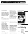
Generates Custom or
Standard Waveforms
The LeCroy 9100 Series of Arbitrary
Function Generators (AFGs) are high
performance ATE or benchtop instru
ments which can generate either
standard or user defined, complex
waveforms with fine point-to-point time
resolution. They are fully programmable
via either GPIB or RS-232. Waveform
generation and editing software is
offered for PC-DOS compatible comput
ers. Applications include: scientific
research, medical instrumentation, disk
drive testing, communication link testing,
radar and sonar testing, ultra-sound
testing and video testing.
HIGH SPEED WAVEFORMS
Custom waveform outputs using digital
generation techniques can now be
created from amplitude points separated
by as little as 5 nsec. Wide-band
amplifiers coupled with high-speed
DACs yield fast rise times and settling
times. Built-in filters eliminate point-to
point steps to present smooth output
shapes at your option. Analog signals to
100 MHz can be created.
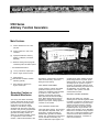
DUAL CHANNEL OPERATION
In the dual output versions, each channel
has independent amplitude, offset, and
phase delay, providing the ability to
simultaneously generate two different
signals. Also, generating the same signal
on both channels and inverting one
results in differential output signals. The
excellent phase match between channels
permits the generat1on of precise, phase
related signals for use in such applications
as testing logic set up times or synchro
resolvers. It is espectally suited tor mixed
signal automated testing for products such
as digital fillers, AID converters, DIA
converters, video systems, and data
communications circuits.
INTERNAL CHANNEL SUMMING
With the 8-bit Model 9109, internally
summing the two channels together makes
it possible to combine two waveforms and
control the amplitude of one portion of the
resultant composite wavetorm indeperl
dently of the rest of it. This also provides
expanded dynamic range because one
portion of the waveform can be attenuated
relative to the rest without losing resolution
(bits). Also, by setting the amplitude range
of each channel to half the desired total
amplitude and summing, a resolution of
9 bits can be achieved.
STANDARD AND ARBITRARY
FUNCTIONS
In addition to the primary function of
arbitrary funct ion generation , the Series
9100 units also provide both standard
f unction generation and pulse generation
capabilities. Sine, square , t riangular,
ramp, pulse and DC-waveform funct ions
are built-in standa rds. Function select ion
and parameter manipulation can be
implemented from t he control panel or
via the GPIB or RS-232-C interface.
DIGITA L AS WELL AS ANALOG
OUTPUTS
Both dual channel models of Series 91 00
generate custom or standard waveforms
and their equivalent digital data patterns.
Their high speeds up to 200 Mpointstsec
make it possible to produce "real world "
custom w aveforms for testing digital
f ilters, RADAR and SONAR signal
processing systems , disk drives , A/0 - D/A
conve rters, video systems . and data
communications systems.
VERSATILE MEMORIES FOR
WAVEFORM GENERATION AND
NON-VOLATILE STORAGE
The A FGs use a high-speed waveform
memory (5 12 kbytes, expandable to
2 Mbytes) to generate waveforms. This
memory can be down-loaded with a
variety of different waveform files or
segments . Wavef orm elements can be
repeated and linked together to create
larger composite wav eforms . There is
no dead time between linked segments.
Each custom wavefo rm can be repeated
up to 65,535 times.
FLEXIBLE OPE RATION AND
TRIGGER MODES
Waveforms can be output as a single
shot. as a triggered burst of up to 64K
cycles , as an auto-triggered recurrent
wave form with programmed delays
between cycles, as a continuous
waveform , or gated under cont rol of
an external signal. Triggering can be
manual, bus operated, or external , with
selectable slope , polarity, level, and
delay . Timemark, sync·d, wavefo rm st art,
and clock outputs provide flexible timing
reference for synchronized operation.
any o· LeCroy's digital oscilloscopes ,
digitizers. or transient ce.co rdm$ , and
transferred to the AFGs.
WAVEFORM AND COMMAND
SEQUENCING SPEED TEST SETUP
AND THROUGHPUT
LeCroy arbitrary function generators let
you store hundreds of waveform genera
tion commands in a single "Sequence
File"_ By activat ing j ust one sequence f ile.
the most complex wavefo rms can be
output easily and automat ically.
OPTIONAL HAND-HELD CONTROL
PANEL
A n optional hand-held control panel
allows test technicians full access to
stored wavefor ms and permits flexible
manipulation of these wave f orms without
the use of a computer.
WAVEFORM CREATION SOFTWARE
LeCroy's optional EASYWAVE software
simpl ifies creation of custom waveforms
or digital data patterns. Wit h EASYWAVE
you can easily and quickly create almost
any conceivable "real world" waveform
required f or comprehensive and realistic
test ing of your circuits.
Waveforms can be created directly
from the mathematical equation which
describes the waveform. Or, i may be
easier to simply select the needed
shapes from EASYWAVE's library of
simple wavefor m elements. link them
together, and t hen st retch them to
desired amplitudes and time durations .
A spreadsheet -like array editor is used
for point-by-poi t wavefo rm or pattern
entry in decimal or hexadecimal form.
Waveforms may also be captured using
Custom waveforms can be captured by a
digital scope or digitizer. and then edited and
regenerated with the Series 9100 A FGs. Or.
they can be created from scratch from simple
elements or equations with our user-friendly
EASYWAVE ·software.
9100 Series Models
Model9101
r
!
Model 9109
J
Single-channel,
200 Mpointslsoc,
8-bit analog outputs.
,
··---!
Dual-c hannel.
200 Mpoints/sec,
!
I
8-bi analog outpu s
l
8-bit digital outputs.
Model 9 112
Dual-cha nel.
50 Mpoi nts/sec.
two 12-bit analog
outputs, two 16-bit
digital outpu s.
-------- --------
j
j
9100 Series Specifications
Waveform Output Characteristics
9101
Output Channel -----
-+----------------
----- --
or 1% of full scale
amplitude or 20 mV
1----------------t---------- ----------Vertical Resolution
8 bits
I
5
mV
P·P
I
-
10 V p p into 50 U ( -5 V to ;5 V]
'0 V p-p 1nto high·Z
10 V p-p into SO !l [-5 V 10 +5 V)
vp
+5
pinto 50
n
20 V p p into high-Z
::5 V p-p into 50 £1
< 6 mV steps
sinusoidal output at
<-50 dBc for
c:-
1
I
Signal-to-Noise Ratio
I
I ::::::.::·:;.,;.,
[_:UngT;m•
I
I
Crosstalk Between
Channels
full scale amplitude
(musl be \. Jith!n outpu vo!1agc range)
< 6 mV steps
0.05% of full scale
I
< -65 dBc for
I
:> 45 dB for full scale
2 45 dB for full sc01le
> 70 dB RMS
amplitudes 2 75 mV
0 v offset
amplitudes 2 75 mV
0 V offset. sum off
(p-p noise s 0.1% of full
scCJie amplitude + 2 mV
excluding glitch Anergy of
50 pV•sec amplitude]
< 20 nsec to 3% of amplitude
change for 5 V transition.
including rise time (filters otf]
< ·65 dBc for frequencies
s 1 MHz, excluding
i
< 5 nsec, 10%-90%. filters off
1
ec, 10%- 90%(5.5 nse ty_JJ)_
. <
5% of full scale amplitude
max. 3% typ
5% of fuil scctle amplit.. ude
20 nsec to 3% of ampl1tude
change for 5 V transition
including nse time (filters off)
<:50 nsec to 1% of
max. 2% typ
<
NA
amplitude change
20 nsec typ
<
0.05% with both channP.Is .et
tor· 10 V amplitude
:1-1 nsec, dual mode,
.i1 nsec
:c0.5 nsec, channels summed
±40V
1
d
band
within i kHz of earner
i
------ ---------- --------
5% of full scale amplitude
max, 3% typ
Channel 1 to Channel 2
Phase Accuracy
Pro_t_e_ct_i_o_n _
I
< -65 dBc for frequencies
s. 1 MHz, excluding band
within 1 kHz of carrier
10%- 90%. filters off
j'
frequencies '£ 200 kHz
---------------·
< -65 dBc for frequencies
< 1 MHz, excluding band
withrn 1 kHz of carrier
< 5 nsec.
j
.
amplitude
Sinusoidal output at
-------- -----I
r
±1 0 V P"P into high-Z,
<-50 dBc for
frequenCies
1 MHz
-----------
frequencies,; 1 MHz
Spurious and
Non-Harmonic
Distortion
-1
12 bits
sinusoidal output at
Distortion
Total Harmonic
I
--------
------+Offset Voltage
Resolution
0.5% of full scale amplitude
into 50 U for
amplitude :> 500 mV
_j
100 pV p-p into 50 n
200 pV p-p into high-Z
+ 1 0 V p-p into high-Z
1
50 n±osn
5 rnV p-p into 50 U
10 nlV p-p into l1igh-Z
into 50 f2
! Maximum Full Scale
10 V p-p into 50 Q (-5 V to +5 V)
i Output Voltage
20 V p-p 1nto 11,g!1 Z
1------ ---- - -- -- ---------+--------------.;-Offset Voltage Range
50 n ±o.s [l
The greater of 1% of level
or 1% ol full scale
amplitude or 20 mV
8 bits
10 mV p-p 1nto l1igh-Z
-------- -------
2
--
------ ------L
Minimum Full Scale
Output Voltage
2
I
The greater of 1% of level
DC Accuracy
9112
1_
son±o.5n
Output Impedance
9109
I
---L----
":40
v
l4GV
I
j
OUTPUT CHARACTERISTICS
Output smoothing (filtering): The 91 01 and
9109 have built-in 18 dB/octave (3 pole
Bessel) filters for P.ach channel with indepP.n
dently programmable cutoff frequencies oi
100 MHz. 30 MHz, 10 MHz, 3 MHz or 1 MHz
Filters may also be turned off. The 9112 is
provided with one external 8-pole Butterworth
low-pass filter. Cutoff fmquency (-3 dB point)
36 MHz, rolloff cc 48 dStoctave. Additional filter
for 2nd channel optional
External Clocking Performance
;
1
i
OUTPUT CLOCKiNG CHARACTERISTICS
Clock resolution: 0.035% (350 ppm).
Clock accuracy: < 5 0 ppm at act1ievable
set points, nt 23 'C. 115 VAC160 Hz. after a
30 minute warm-up period.
Clock stability:< 0.5 ppm· C
Clock jitter: 0.05% max .. 0 0125% typical.
Interval range:
Maximum
Output Rate
I
I
----·!
Single
m1
200
Mpo111h/sec
:
i
200
1
I
I
------·-----!---- -
5 nsec-
: 20 nsec · 1
r;;; ::: - -,G;::,, ;;;; : , ;;;; : ,
i
per channel per channel
j
External clocking: Output point rate may
also be controlled by an external clock source.
When external clocking is selected. the
internal clock is bypassed and the waveform
is generated using the external clock The
External Clocking Performance table
describes the relationship between the
external clock frequency and the output point
rate in various coniigurattons.
External clock input impedance: 50 n.
External clock threshold: Variable over the
range of ±2.5 V. Resolution< 20 mV.
'
9112in
I
Dual Channel
i
Mode
:
I
Mode
I
200 M z ----2 0 Hz--1 -
None
.,.2
200 Mpo1nts/sec
-L -----
9112in
i
-z--
!
1
<-4
·
100 Mpoints:s._e_c . 5_0_M_pointsisec
-·- -
-
r- h n l
50 Mp:i s:!Tc
I
=r channel
I
This table describes the relationship between the external clock frequency and the output point
rate m vanous conttguratJOns.
12 5;--1
! Mpointsi:;ec 1 Mpointsisec
------- t··
5 nsec-
g ;- 1
Mode
I
: Single Channel
+--------------- ----
Maximum Output
L_S_'a_rT_1P_I:_Rat
9109in
Dual Channel
200 MHz
Clock
F_re_q_u_e_n_cy
Clock Divider
9101,9109
Single Channel
Mode
TRIGGERING CHARACTERISTICS
Trigger Modes
Continuous: The generator runs continuously
at the selected frequency.
Recurrent: The waveform is cycled with a
programmable delay between cycles. The
number of waveforms per cycle is program
mabie up to 65.535.
Single: Upon receipt of a trigger. the selected
waveform is generated only once. The start of
the v.raveform can be programrnably delayed
from the trigger point.
Burst: Upon receipt of a trigger, the selected
waveform is generated a programmable
number of tirnr;s, up to 65.535. The start of the
burst can be programmably deiayed from the
trigger point.
Gated: The waveform is triggered by the
leading edge of the gate stgnal, and stops at
the completion of the waveform cycle
occurring during the trailing edge of the gaie
signal.
Trigger delay: Programmable; limits depend
on genemtor model and single or dual
channel operation. The limits are given in the
Tngger Delay Limits table. In the table, the
term "point" indicates one sample interval's
Trigger arming sources:
Auto: Generator automatically rearms itself
at the end of the waveform.
Bus: Generator is rearmed only via
command from the GPIB, RS-232 or the
9100/CP Hand held Control Panel.
Triggering sources:
Manual: Front panel push-button.
External: External trigger applied via a front
panel BNC.
Bus: Trigger from GPIB of RS-232.
Control Panel: Trigger key.
External trigger input:
Impedance: 50 n.
Slope: Positive or negative threshold.
Range: ±2.5 V.
Threshold resolution: < 20 mV.
Trigger Delay Limits
I
9101,9109
f -- -----·---I
• M1nirnum
I
Maxi
I
--m---- -·-
Single Channel
Mode
9109in
9112in
9112in
Dual Channel
Dual Channel
Mode
Single Channel
Mode
4 po1nts
2 points
2 point
1 Mpoint
500 kpoints
500 kpoints
----
Mode (min.)
---+----·1-p ;-;;;--250 kpoint0
----L--------- '
WAVEFORM MEMORY CHARACTERISTICS
All LeCroy 9100 Series Arbitrary Function
Generators (AFGs) have 512 kbytes of high
speed waveform memory as a standard
feature.
Waveform memory may optionally be
extended to 1 Mbyte with the /MM1 option
or 2 Mbytes with the !MM2 option.
The 9101 and the 9109 use one high speed
memory byte per waveform point. The 9112
uses 2 bytes per point. Therefore, with U1e
9112 the standard configuration provides
256 kpoints, the /MM1 option provides
512 kpoints and the ;MM2 option provides
1 Mpoint
DIGITAL OUTPUT CHARACTERISTICS
Two digital output channels are standard
features of LeCroy's 9109 and 9112 Arbitrary
Function Generators. Each of the two
channels has bot11 a digital and an analog
output port. This allows users to utilize data
in both the digital and analog domains. This
feature is useful in mixed signal test and
development applications.
hardware. Data written to the FIFO is used
instead of the contents of the Qenerator"s
Control Memory. whicll normally controls the
sequencing of output waveforms.
Compatibility: This option is fully compatible
with all LeCroy 9100 Series AFGs.
Maximum real-time waveform selection
rate: 2.77 MHz. !or 72 point single-channel
waveforms at 200 MHz s::1mple rate in 9101
and 9109. or for 18 point dual-channel
waveforms at 50 MHz sample rate in 9112.
Fetch time for waveform change instruc·
tion: 72 sample clock periods.
Throughput delay: (from nsing edge of write
to output change) 121 sample clock periods
+ 120 nsec. relative to the end of the
waveform currently being output
The 9212 uses a 16-bit memory architecture.
The !our least significant bits of each of the
9112's data words are not delivered to their
respective DACs. and may therefore contain
time-correlated data which do not aftect the
analog waveform generated by that channel.
(The Digital Output feature is unavailable in
Model 91 01.)
Individual waveform files, or segments. may
be linked to create larger composite wave
forms. There is no dead time between linked
segments.
Memory Segment Length Requirements
-----,-
The maximum number of links in a composite
waveform is 2048. Each linked segment can
be repeatedtoup
4095linked
timessegment.
before
advancing
thetonext
Single Channel
l'
.
Regardless
of how
times awaveform.
given linked
segment
is used
in amany
composite
it
Minimum
Linkable
Segment Lengrn
appears in high-speed memory only once.
The Memory Segment Length Requirements
table describes segment length requ1rements.
REAL-TIME OPERATING MODE
The 91 00/RT option allows immediate,
interactive access to any waveform file in
the AFG's high-speed waveform memory.
This gives the user the ability to change the
output waveform Han !he fly", in a smooth and
continuous fashion. The option consists of a
First-In, First-Out (FIFO) memory and support
I
9101,9109
i
Mode
9112in
9112in
36 po1:t_s
72 point ·--+·- ts!ch
65,853p6olpnotsints I
Segment Length
Resolution
_ji
I
+
st.
-- 8p\s_1c_h_
I
I
II
DualMode
Channel
_
I
1
I
i
Maximum
Segment Length
9109in
DualMode
Channel-----1---M_ode
Single Channel
32,768 pts'ch
32.76B·p;;;i.nt
points
4 ptsich
blocks
blocks
blocks
'
1o6 _384
2 pts/ch
J
blocks
1
,,_ _j
'
1
9109 and 9112 Digital Output Specifications
··----- ---· -
--
----+'
II
o_ut g- _
Sat;:;-- -- i
e_rn_a_l v_olta_ge_
--
·1.55 V
+0.5 V ·-
v
J
._l
.,._,_: J_
+2.7V@J
455 V
+0.75 V@ ·3.2 mA
-0.5
,
v
9112
_.J
s_o_M_words'!;eC_
+2.7V@ 1 rnA
.
5-5 ·'
oO 75 V (ell 3" rnA
+0.5
f
_j
I
i
v
t-----·-2._0
,
OutputWordlength
"2oo Mbyt e : 80_":'?Y1C sec
---
' Vout low (max)
J'Maxirnum
I
I
·--
9109TTL_·---+-- ...
1
aximum Data Rate
r
·--------..
9109 ECL' -----L..
J
Digital ClockOutp j
Two8-bitwordsor
TwoR-bitwordsor
one 16-bit word_..J-_on!l1 ·bit
differential
single-ended
J
1
Two16-bitwordsor
_ 9ne 32 bit w (j_
single-ended
• Each channel individually configura.ble for ECL or TTL output by internal jumper selection.
J
1
.
j
AUXILIARY INPUTS AND OUTPUTS
Outputs: AI\ ot the AFGs in LeCroy's 9100
Series feature five timing outputs which may
be used to help synchronize other devices in
your test system to the AFG's output. Two
Sample Clock outputs (located on the rear
panel) are prov1ded. as well as three t1ming
pulse outputs (located on the front panel),
Timing outputs: The Time Marker, Sync
Tngger and Waveform Start Outputs are
described below.
Time marker output: Occurs at a program
mable time after the trigger. Limits are the
same as lor Trigger Delay (see the table in
the Trigger Characteristics section of this
Specification).
Sync trigger output: Occurs at the next
sample clock edge after receiving a Trigger.
Waveform start output: Occurs at the start
of the waveform. This is the only t1ming
output available in Continuous trigger mode.
Output impedance: 50 u
Output levels: TTL into a high impedance.
1 .5 V 1nto 50 U Outputs are positive-going
pulses of approximately 75 nsec duratron.
Output protection: Externally applied
voltages should not exceed -0.5 V or +5.0 V.
Clock outputs: These outputs are
squarewaves at the sample frequency lor
single channel waveforms in the 9101 and
9109. at twice the sample frequency for dual
channel waveforms in the 9109 and for single
channel waveforms in the 9112, or at 4 times
the clock frequency for dual channel wave
forms in the 9112.
Clock Out 1: Present in all modes including
Ext. Clock. Active even if no wavelorm is
being generated.
Inputs: The followmg characteristics apply to
the inputs of LeCroy's 9100 Series Arbitrary
Function Generators
Protection: The maximum input voltage
level for ail inputs should not exceed =5 V,
External trigger/gate input: Input impedance
50 12. Threshold level ±2.5 V. < 20 mV
resolution. See Triggering Characteristics
section for more deta1l.
External clock input: Input impedance 50 11.
Tr1reshold level ±2,5 V. < 20 mV resolution,
See Output Clocking Characteristics section
for more detail
Sum input: (not available on 9112)
Impedance: 50 0.
Gain: x1, ±5% for> 350 mV full scale output
ranges.
Bandwidth: > 80 MHz at 3 dB
Hand-held keypad (control panel) input: A
DIN connector is provided for attaching the
optional hand held control panel and display.
STANDARD FUNCTIONS
Any member of LeCroy's 9100 Series of AFGs
can be operated as a standard function
generator. a pulse generator. or a precision
DC source, as well as an arbitrary function
generator.
Standard Function Mode
The user selects the desired function (sine.
square, ramp or tnangle). and frequency. The
AFG uses these selectrons to calculate the
data file and samole rate most suitable for
generation of the 'requested output signal, in
a manner transparent to the user. In the dual
channel generators (9109 and 9112), the
phase of the signal on Channel 2 is indepen
dently programmable. The Standard Functron
Frequencies table describes the frequencies
obtainable lor the various standard functions
rn eacr1 generator type.
Pulse Generator Mode
The user specifies the repetition rate, delay
and width of the desired pulse output. and
tt1e AFG calculates the best sample rate and
datil pattern to meet those characteristiCS
Note that the Pulse funct1on 1s only available
in S1ngle Channel mode (i.e.. even in the 2·
channel generators, pulses will only be output
on Channel 1 ). The table below gives the
pulse parameter limits.
DC Mode
Allows the AFG to operate as a source of
precise DC voltages. Any DC output voltage
within the range of ± 10 V into 50 n (±20 V tnto
a high-Z) may be programmed,
Standard Function Frequencies
,------,,------------9101
----------,--------------,
9109
------ ----
9112
I
--------r
Sine
!
Clock Out 2: Active only wr,en waveforrn is
---------------- ----------0 01 Hz to 25 MHz
0 01 Hz to 25 MHz
------ ------------------ -
being generated. Quiescent during trigger
delay. re-arm interval, etc. Used <'IS Master
clock for Master-Slave operatron.
'
Triar.g!e
0.01 H.:: to 25 tv1Hz
-----
0.01 Hz to 1 00 MHz
r--Square•
Output impedance: 50 !:1.
Ramp..
40 nsec to
_o_._ot H_z_to_ _ _s M_H_z
--------
0.01 Hz to 6.25 MHz
+-j
0.01 Hz to 100 MHz
---- ---------+
-- --
40 nsec to 100 soc
o ._0_1 _Hz
to 6.25 MHz
0,01 Hz to 25 MHz
160 nsec to 100 sec
100 sec
Output levels: NIM logic levels (0 to -0.8 V)
into 50 U. Can be configured at factory for
ECL levels into 50 n.
Output protection: Externally applied
voltages should not exceed ±2.5 V.
i
---
-·
• In the 9101 and 9 f 09, frequencies up to 100 MHz may be programmed. but 5 nsec rise
and fail time limits still apply
··Ramp orientation may be posit:ve- or negative-gomg
PROGRAMMABILITY
A ll of LeCroy's 9100 Series Arbit rary Function
Generators feature both GP IB (IEE E-488) and
RS- 232 in erfaces as standard equipment.
GPIB: IEEE 486-1978 compatible.
Implement ed interface f unctions are SH1 .
AH 1. TS. T EO. L3. LEO. SA1 . RL 1 . PPO,
DC1, DT 1, and CO
DMA rates:T ypically <:: 200 kbytes/sec.
Data formats:
910 1 & 9109:
Wavefo rms:
#A Binary or #L ASCI I HEX "00" to "FF"
(double the lengt h of internalfy stor ed binary
data f iles).
Other Files:
#I Arbitrary lengt h A SCII
ill..12:
Waveforms:
119 Binary or IlL ASC II HEX '·OQOO " to '·FFFF"
(double the length ol internally st ored binary
data files).
Other Files:
#0 A r bitrary length ASC II
RS-232: Implemented as Data Communica
tions Equipment ( DCE).
Baud rates: 300 , 1200 , 2400. 4800. or
9600.
Dala bits: 7 or 8.
Stop bits: 1 or 2.
Parity: None, even, or odd.
Protocol : Full duplex . Xon/Xotf ( DC1!DC3)
handsha ke.
Commands: Full co ve rsationAI, sAme as
GPIB plus: RS_ SRQ, Defin'3 character
equiva lent to SRQ in GPIB (def ault is "Bell''),
ESC commands, ECHO on/off. Trig remote/
local.
ENVIRONMENTA L & GENERAL
CHARACTERISTICS
Temperature range: 15'C. o 35·- c, lull
spec ific< t ion; 0'&to 40· . operat ing.
Humidity : 40°C, 10% t o 95% relative , non
condensing.
Power : 1151220 VAC . ±20%. 47 -63 Hz.
Approx imately 147 W. For 440 Hz operation ,
cont act fac tory .
Size: 5.25'' H x 19'' W x 15" D.
Weight: 26 lbs. (approximately).
W AVEFORM DEVELOPMENT SOFTWARE
LeCroy currentl y offers two diffP.rent sof tware
packages to support our arbitra ry !unction
generato r pr oducts . EASYWAVE is a menu
driven system designed to get new AFG usP.rs
"up 10 speto!d'' on t lleir new lool qu1ckly a d
easily. W.A.V ..1 S an ex ended programming
environment for the creation of advanced.
complex wave f orms flnd lesl programs
involving multiple instruments. Each of t hese
packages is described i n more detail on
separate data sheet s as Models 91 OOISW
and 9100 'SP respec tively .
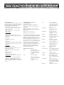
ORDER ING INFORMATION
9101
8-bit . 200 MS;sec ,
single-chi'!nnPI flr bit rary
funct ion generato r with
5 2 kbyte w avefo r m
memory.
9109
8-bit , 200 MS/sec
dual--channel amitra
lunclion generator w ith
digital word outputs and
5 1 2 kbytc wav eform
memory .
9112
91001MM1
9 1001MM2
9100/RT
91001SW
9100/SP
91001CP
9 100/ EC
FILTE R/36 MHz
9100/SM
9 fO O!OM
9 100/GPIB2
DC/GPIB
12-bil, 50 MS/sec.
dual-channel ilrbit rary
funct ion generator with
digital wMd output and
512 kword wave·orm
memory .
Wnvcfor m memory
expansio to 1 Mbyte
(Sl ;:> kword)
Wavelo rm memory
expansio to 2 Mbyte
(1 Mword).
Real-time, int eract ive
w ilv<!f orm selectio n.
EASYWAVE··menu driven
wave f or m creat ion
so twa re .
W.A.V.E. , <: dva nced
wavefo rm Greation and
A illy i soltware.
Hand-held control panel
f or arbitrary funct ion
genera ors wit h 6 ft.
conoecting cable.
Extend r cable f or
9 100/CP.
Ext a 36 MHz . 8 pole low
pass Bulterworth f ilter for
91 12 (one supplied with
unit).
A rbitrary f unction
generator service manual.
Extra ar bit rary f unction
ge ernt or opcro or's
manual (one suppl ied w ith
unll).
Nationa l lnS!rument s
PCJI'if, GP I B lnter tacCa rd
and Soflware f or IBM PC/
XT/AT '") and compat ibl e
computers
GPIB cable. 2 meters.
Pulse Paramete rs
1------Period
r---
W idt h_
Dolay
I
9101
9109
9112
40 nsoc to 1o sec
40 n ec to 10 sec
160 nsec to 10 sec
5 nsec to 10 er:
s
20 osec..to 10 sec
Widt h -W:le lay
must be < Period
35 nsec to 5 msec
Width + Delay
must be < Period
·--------
25 nsec to 5 msP-c
Q$('C
-·
to t 0 sec
25 nsec to 5 msec
'
--
Comments
-